

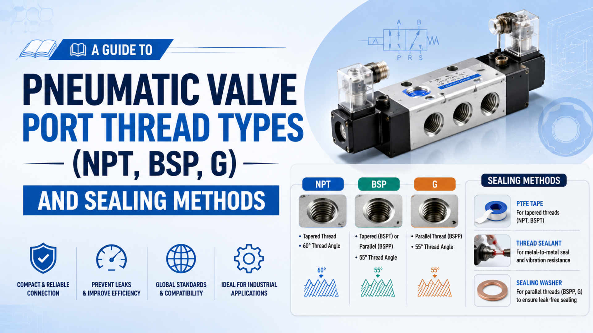
A pneumatic valve port connection is compatible only when three things match: the thread standard, the nominal size, and the intended sealing interface. NPT, ISO 7 R-family threads, and ISO 228 G threads can carry similar commercial size labels, but they do not share the same geometry or sealing method.
Valve work adds another layer. A marking such as supply, working, exhaust, or pilot identifies what the port does. It does not identify whether that port is NPT, Rc, G, or a gasketed manifold passage. Read the pneumatic symbol and the mechanical drawing separately.
Key Takeaways
- ASME B1.20.1, ISO 7-1, and ISO 228-1 define 3 different pipe-thread families.
- “BSP” alone is incomplete because it does not distinguish tapered from parallel threads.
- G threads retain the fitting; a separate surface and seal normally create pressure tightness.
- A compatible adapter must satisfy both threaded interfaces, both seals, pressure, flow, and valve-body limits.
Why Is “BSP” Incomplete on a Valve Drawing or RFQ?
ISO uses 2 separate standards for the threads commonly grouped under “BSP”: ISO 7-1 covers joints made pressure-tight on the thread, while ISO 228-1 covers parallel threads whose pressure seal is made outside the thread (ISO 7-1; ISO 228-1, accessed July 22, 2026).
The commercial terms BSPT and BSPP are useful in conversation, but they are not equally precise on a drawing. For valve replacement and fitting procurement, use the designation from the component documentation:
| Designation | Thread form | Typical mating relationship | Where the pressure seal is intended |
|---|---|---|---|
| NPT | Tapered, 60 degree form | Male NPT with female NPT | Tapered thread engagement plus approved sealant |
| R | Tapered external, 55 degree form | R male with Rc or Rp female as specified | On the ISO 7 threaded joint |
| Rc | Tapered internal, 55 degree form | Usually R male | On the ISO 7 threaded joint |
| Rp | Parallel internal, 55 degree form | R male in the specified ISO 7 combination | On the ISO 7 threaded joint |
| G | Parallel internal or external, 55 degree form | Matching ISO 228 thread plus a defined stud-end or fitting seal | On surfaces outside the thread |
Calling an unknown port “BSP” leaves at least three unanswered questions: Is it tapered or parallel? What is the exact internal or external designation? Where is the joint supposed to seal? A fitting that turns several threads by hand does not answer any of them.
The safest replacement language is not “1/4 BSP.” It is a complete callout such as G1/4 female with the documented face seal, Rc1/4 female, or the exact manufacturer part number. The sealing feature belongs in the specification because nominal thread size alone cannot define a pressure-tight valve connection.
The existing cylinder port thread guide covers the same standards at an actuator port. This article stays with threaded valves, manifolds, adapters, silencers, and replacement-valve acceptance.
Three Standards Define the Relevant Valve-Port Threads
For replacement-valve interfaces, ASME B1.20.1 covers dimensions and gaging for 5 related inch pipe-thread designations, including NPT, while ISO 7-1 and ISO 228-1 separate pressure-tight threaded joints from parallel fastening threads (ASME B1.20.1; ISO 7-1; ISO 228-1).
NPT Belongs to ASME B1.20.1
NPT is a tapered inch pipe thread with a 60 degree form and a 1:16 change in diameter along the thread axis. The taper creates wedging engagement, but ordinary NPT joints normally still need an approved thread sealant to close the helical leakage path.
NPTF is a separate dryseal designation. Do not replace an NPTF callout with NPT merely because the parts appear to assemble. The standard, gaging, thread condition, material, sealant rule, and valve manufacturer’s instructions all matter.
The ASME B1.20.1 NPT guide provides the size-specific pitch and gaging background. This article uses NPT only as one branch of a valve-port decision.
R, Rc, and Rp Belong to ISO 7-1
ISO 7-1 applies where the joint is intended to become pressure-tight on the thread. R identifies an external taper thread, Rc an internal taper thread, and Rp an internal parallel thread used in the defined ISO 7 joint.
An Rp female thread is not the same specification as a G female thread simply because both are parallel and use the same nominal size family. Their purpose, tolerances, mating designation, and sealing concept must be checked against the correct standard and product drawing.
G Belongs to ISO 228-1
ISO 228-1 covers parallel threads from size 1/16 through 6 and states that these threads are not suitable when the pressure-tight joint is made on the thread. Pressure tightness is instead achieved by compressing sealing surfaces outside the threads with an appropriate seal.
That wording is important. A G-thread valve port may use an O-ring, a bonded washer, an elastomeric stud-end seal, a gasket, or a product-specific metal sealing arrangement. “G thread” does not identify one universal O-ring groove.
Where Does Each Valve Port Actually Seal?
ISO 228-1 defines parallel thread sizes from 1/16 through 6, yet explicitly places the pressure seal outside those threads (ISO 228-1, confirmed 2022). The practical inspection rule is simple: identify the surface that carries seal compression before deciding whether tape, liquid sealant, a washer, or an O-ring belongs there.
A valve-port joint usually follows one of these sealing boundaries:
| Sealing boundary | Thread’s job | Seal’s job | Common failure mode |
|---|---|---|---|
| NPT tapered thread | Retains fitting and creates tapered interference | Compatible sealant fills remaining leak paths | Wrong thread, damaged flanks, excess or missing sealant, over-engagement |
| ISO 7 R/Rc or R/Rp joint | Retains fitting and forms the specified pressure-tight thread pair | Approved sealant supports the threaded joint as required | NPT substitution, wrong mating designation, pitch damage |
| G port with face seal | Retains and clamps the fitting | Gasket, bonded washer, or face O-ring seals on a machined surface | Missing seal, scratched spotface, wrong washer thickness |
| G port with ISO 1179 stud end | Retains a defined stud end | Type-specific elastomeric or metal interface forms the seal | Wrong stud-end type, damaged port geometry, seal extrusion |
| Manifold-mounted valve | Fasteners retain the valve to the base | Interface gasket or O-rings seal machined passages | Misaligned gasket, damaged surface, wrong manifold pattern |
PTFE tape on a parallel G thread cannot recreate a missing spotface seal. Tightening a G fitting harder may load the valve body without increasing the designed seal compression. Likewise, an O-ring placed under an NPT hex does not convert a tapered NPT port into a face-sealed port unless the manufacturer designed that interface.
ISO 1179 demonstrates why the complete stud-end design matters. It covers ISO 228-1 threaded ports used with several elastomeric and metal sealing arrangements, and it states that permissible pressure depends on size, materials, design, working conditions, and application (ISO 1179-1, 2013).
Never assign a universal pressure rating to NPT, “BSP,” or G. The allowable assembly pressure is limited by the valve body, port wall, fitting, adapter, sealing element, temperature, medium, vibration, and any applicable approval.
How Do Port Function and Thread Designation Differ?
ISO 11727:1999 uses 11 pages to establish identification rules for main-flow, control, and pilot-supply connections on pneumatic control valves and related components (ISO 11727, confirmed current). Those functional markings describe the air path. They do not specify the port’s thread geometry or seal.
A directional valve may have supply, working, exhaust, pilot-supply, and pilot-exhaust connections. Depending on the product, these may be marked by numbers, letters, symbols, or a combination. Always follow the valve symbol and catalog because commercial naming conventions and accessory markings can differ.
| Information source | What it tells you | What it does not tell you by itself |
|---|---|---|
| Pneumatic symbol | Which ports connect in each valve position | Thread standard, size, seal, or fitting material |
| Port number or letter | Functional identity of that connection | Whether it is NPT, Rc, G, or a manifold passage |
| Mechanical drawing | Thread callout, port location, spotface, depth, clearance | Internal switching logic unless the symbol is included |
| Ordering code | Configured thread, voltage, actuation, manifold option | Condition of an unidentified installed valve without the full code |
| Fitting label | Fitting thread and tube connection | Valve port identity or compatibility with a damaged port |
This separation prevents a common purchasing error: ordering the correct valve function with the wrong port interface. A 5/2 replacement can route air correctly on paper yet remain unusable because its supply and exhaust ports changed from Rc to G, or because a manifold version was substituted for an individually ported body.
The same principle applies to flow. A G1/4 label identifies a thread size and form, not the valve’s effective orifice, Cv, sonic conductance, or pressure-drop behavior. Confirm flow performance separately from thread compatibility.
The valve port size versus internal orifice guide explains why two valves with the same threaded connection can deliver different flow.
Manifold-Mounted Valves Move the Sealing Boundary
ISO 5599-1:2001 is an 8-page standard for 5-port directional-valve mounting interfaces and was confirmed current in 2024 (ISO 5599-1). A manifold-mounted valve can therefore seal through machined passages and an interface gasket, while the threaded supply, working, and exhaust connections reside in the base or end plate.
This changes what must match during replacement. The spool valve may have no user-accessible pipe thread at all. Its compatibility depends on the mounting pattern, passage positions, gasket geometry, fastener pattern, valve size, pilot arrangement, electrical connection, and manifold family.
Do not infer manifold compatibility from a shared thread option. Two product families may both offer G1/4 end-plate ports while using completely different valve-to-base interfaces. Conversely, the same valve body may mount on several bases that provide different NPT, Rc, G, or tube-fitting connections.
For a manifold replacement, divide the interfaces into three records:
- Valve-to-base interface: mounting pattern, passage layout, gasket, fasteners, and pilot arrangement.
- Base-to-pneumatic circuit: supply, working, exhaust, pilot, tube, and threaded connections.
- Valve-to-electrical system: voltage, connector, suppression, polarity, bus node, and diagnostics.
The threaded port visible on a manifold may belong to the end plate rather than the valve being replaced. Photograph the valve label, base label, end plate, gasket face, and external ports separately. Otherwise, an RFQ can combine the valve’s electrical code with the base’s thread code and produce a configuration that never existed.
How Can You Identify an Unknown Threaded Valve Port?
Parker’s field guide uses 4 steps to identify an unknown connection: determine thread type, measure diameter, determine pitch, and compare the result with a thread chart (Parker thread identification guide, accessed July 22, 2026). Valve work also requires inspection of taper and the separate sealing surface.
Start with the full valve or manifold part number. Catalog suffixes often distinguish Rc, G, NPT, or NPTF versions within the same body size. A country of manufacture, tube size, or nearby fitting is only a clue. An adapter may already be installed and can hide the actual valve port.
If the documentation is unavailable, use this controlled identification sequence:
- Isolate electrical and pneumatic energy under the machine’s approved procedure.
- Remove the fitting without using the damaged connection as a reference.
- Inspect for taper, a flat spotface, an O-ring recess, a bonded washer, or sealant residue.
- Measure male outside diameter or female reference diameter at defined locations.
- Measure pitch with a thread gauge in TPI or millimeters.
- Compare thread angle and taper with the likely NPT, ISO 7, or ISO 228 family.
- Confirm the designation with a drawing, catalog, or correct reference gauge.
- Inspect the port wall, first thread, spotface, and passage for damage before reuse.
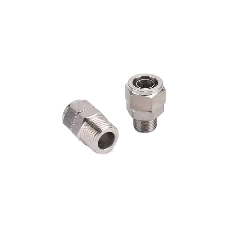
External shape cannot prove whether a male fitting is NPT, R, G, or another standard. Measure the thread and identify its sealing feature.
A tapered small-diameter fitting can appear parallel over a short engagement. A G and Rp female thread can share a 55 degree parallel form yet belong to different joint concepts. A damaged NPT or Rc port can also distort screening measurements. Use a standard gauge for manufacturing acceptance or safety-critical repair.
Never identify a valve port by forcing in a known fitting. Early binding, wobble, unusual depth, or a need for high torque signals incompatibility or damage, not a connection that needs more effort.
How Should NPT, R-Family, and G Ports Be Sealed?
SMC’s SY valve catalog lists 4 selectable thread codes across relevant configurations: Rc, G, NPT, and NPTF (SMC SY 5-port solenoid valves, accessed July 22, 2026). That product-level separation is the correct installation model: identify the configured valve first, then use its matching seal and tightening instruction.
NPT Installation
Clean and inspect both threads. Apply only a pneumatic-compatible sealant allowed by the valve and fitting manufacturers, normally to the male thread. Keep loose tape and excess liquid compound out of the first thread and flow passage. Start by hand, then follow the specified engagement or torque instruction.
There is no safe universal NPT torque table for every valve. A stainless fitting, brass valve, aluminum manifold, zinc casting, and polymer body can fail at different loads. Tapered engagement acts as a wedge, so more torque can crack a thin female port rather than stop a leak.
ISO 7 R-Family Installation
Confirm the exact pair: R with Rc, or R with the intended Rp port. Use the sealant and engagement instruction specified for that product. Do not substitute NPT because both fittings are tapered. Parker’s installation manual explicitly warns that BSPT is not a substitute for NPT (Parker fitting installation manual, accessed July 22, 2026).
G-Thread Installation
Identify the actual sealing element before installation. Inspect the spotface, O-ring, washer, gasket, stud end, and any locknut or orientation feature. Replace a cut, flattened, swollen, hardened, or incorrect seal. Tighten the fitting through the specified feature so the designed surfaces compress the seal.
Do not add PTFE tape to a G retention thread unless the component manufacturer explicitly designed and approved that sealing method. Tape cannot repair a scratched face, missing washer, wrong stud end, or damaged O-ring groove.
For the tube side of a threaded fitting, follow the push-in fitting installation guide. A leak at the release collet is a different fault from leakage around the threaded valve port.
Adapter Selection Creates Two Interfaces to Validate
ISO 1179-1 references 4 sealing types for ISO 228-1 port arrangements: E, G, H, and B, with allowable pressure varying by seal type, size, material, and application (ISO 1179-1, 2013). An adapter adds a second thread and seal, so both ends need complete specifications and ratings.
An NPT-to-G adapter can be a controlled engineering solution when the valve cannot be sourced with the machine’s native connection. It should not be treated as proof that NPT and G are interchangeable. The adapter contains one NPT joint and one G joint, each installed according to its own sealing method.
Check these items before approving an adapter:
- exact male and female designation on both ends;
- sealing method and supplied sealing element for each end;
- pressure, temperature, medium, corrosion, and vibration rating;
- minimum internal bore and effect on valve flow;
- added length, wrench clearance, and interference with coils or manual overrides;
- bending load from rigid tubing, hoses, silencers, and unsupported accessories;
- hazardous-location, hygiene, material, or regional approvals;
- availability of replacement seals and identification marking.
Avoid stacking adapters to solve an uncertain thread identity. Each connection adds tolerance, leak, flow, and maintenance boundaries. If two adapters are required, compare that assembly with a valve or manifold base supplied in the correct native thread.
In our experience, the most useful adapter record includes a photo, both part numbers, the valve port drawing, the sealing element, and the final orientation. That small record prevents the next technician from measuring the exposed adapter and mistakenly ordering it as the valve’s original port.
What Does a Persistent Valve-Port Leak Tell You?
Parker’s thread-identification material separates 4 tasks before any replacement fitting is installed on a valve: thread type, diameter, pitch, and chart comparison (Parker). A leak that returns after seal replacement should restart that identification process before anyone adds torque, tape, or compound.
| Symptom | Likely diagnostic branch | First controlled check |
|---|---|---|
| Fitting binds after one or two turns | Wrong pitch, wrong form, cross-threading, damaged first thread | Remove and identify both interfaces with gauges |
| Tapered fitting enters unusually deep | Oversize, damaged, or mismatched female port | Compare engagement with the product drawing or correct gauge |
| G fitting is tight but leaks under the hex | Missing or damaged face seal, scratched spotface, wrong stud end | Inspect the sealing surface and specified seal |
| Leak appears at the manifold seam | Gasket misalignment, wrong interface, surface damage, loose fasteners | Isolate, remove the valve, and inspect base pattern and gasket |
| Leak returns after vibration | Unsupported tubing, loose locknut, cracked body, damaged seal | Remove side load and inspect the complete assembly |
| Exhaust port seems to leak continuously | Valve switching, spool leakage, wrong silencer port, downstream backflow | Confirm pneumatic symbol and isolate external port leakage from internal leakage |
| Port cracks during tightening | Taper wedge load, excessive torque, cross-threading, thin or damaged body | Replace the damaged pressure boundary and review the fitting specification |
| Debris appears downstream | Excess tape, compound, thread chips, damaged seal | Clean the circuit and correct the assembly method |
Localize the leak before disassembly. Bubbles at the fitting-to-valve boundary, tube collet, manifold gasket, coil operator, or exhaust port point to different failures. A directional valve can also pass air internally through a worn spool or seat even when every threaded joint is tight.
If chemical attack or corrosion damaged the port, use the corrosion-resistant fitting guide before changing alloy or seal material. Thread compatibility does not prove media compatibility.
What Should a Replacement Valve RFQ Specify?
SMC documents at least 4 thread options in applicable SY configurations, while ISO 11727 separately standardizes pneumatic control-valve port identification (SMC SY catalog; ISO 11727). A replacement RFQ must therefore state both what every port does and how every external interface connects and seals.
| RFQ field | Required information | Why it matters |
|---|---|---|
| Installed identity | Manufacturer, complete model code, revision, photos | Finds the configured thread and manifold option |
| Valve function | 2/2, 3/2, 5/2, 5/3, normal state, center condition | Confirms the required air paths |
| Port map | Supply, working, exhaust, pilot supply, pilot exhaust | Prevents functional-port confusion |
| Thread designation | NPT, NPTF, R, Rc, Rp, G, size, gender | Prevents near-match assembly |
| Seal arrangement | Thread sealant, face seal, bonded washer, O-ring, gasket, stud-end type | Defines pressure-tightness |
| Mounting interface | Individual body, sub-base, manifold family, ISO interface, gasket | Confirms valve-to-base compatibility |
| Pneumatic limits | Pressure range, minimum pilot pressure, medium, flow, leakage | Verifies function after installation |
| Environment | Temperature, washdown, vibration, corrosion, hazardous area | Checks body, seal, fitting, and approval |
| Electrical interface | Voltage, AC/DC, connector, suppression, polarity, bus system | Prevents a mechanically correct but unusable replacement |
| Acceptance evidence | Drawing, certificates, leak test, port-pressure test, cycle test | Defines release criteria |
Do not send only “G1/4 valve.” That leaves the function, seal, manifold pattern, pilot arrangement, flow, voltage, and approvals undefined. Likewise, do not copy the thread from an adapter attached to the installed unit without confirming the underlying valve port.
Use the OEM solenoid-valve compatibility checklist for electrical, pneumatic, dimensional, and approval checks beyond the threaded interfaces.
After installation, restore pressure gradually under the machine’s approved procedure. Verify external leakage, energized and de-energized port states, pilot operation, working-port pressure, exhaust behavior, and production-cycle acceptance. A dry threaded joint is not enough if the valve routes air incorrectly or restricts the required flow.
When the replacement also changes Cv, port size, or manifold passages, complete the separate pneumatic valve sizing review before releasing the machine.
Pneumatic Valve Port Thread FAQs
Three standards control the main thread branches discussed here: ASME B1.20.1 for NPT-family inch pipe threads, ISO 7-1 for pressure-tight R-family threaded joints, and ISO 228-1 for parallel G fastening threads (ASME; ISO 7-1; ISO 228-1). The questions below apply those distinctions to valve replacement.
Are BSPP and G threads the same on pneumatic valves?
BSPP is a common commercial name for the parallel pipe-thread form designated G under ISO 228. However, a G size does not define the complete pressure seal. Confirm the valve’s spotface, stud end, gasket, bonded washer, O-ring, or other documented sealing arrangement before selecting the fitting.
Can a BSPT fitting be installed in an NPT valve port?
No. Both are tapered, but NPT uses a different thread form from the ISO 7 R-family commonly called BSPT. A fitting may start into the wrong port and still damage the threads or leak. Identify angle, pitch, taper, and designation, then use a properly specified adapter if conversion is necessary.
Does a G-thread valve port always use an O-ring?
No. ISO 228 places pressure sealing outside the parallel thread but does not mandate one universal seal. Valve and fitting designs may use an O-ring, bonded washer, gasket, elastomeric stud-end seal, or defined metal interface. The port drawing and fitting standard must identify the mating surfaces and sealing element.
Should PTFE tape be applied to every pneumatic valve thread?
No. Tape may be permitted on some NPT or ISO 7 threaded joints, but it does not replace the external seal on a G port. Excess tape can enter small pilot passages or spools. Follow the exact valve, fitting, and sealant instructions, including preparation, application amount, engagement, and cure time.
Can the port thread size be used to compare valve flow?
No. Thread size only describes one mechanical interface. Valve flow also depends on internal orifice and spool geometry, pressure ratio, manifold passages, adapters, silencers, fittings, and tubing. Compare the supplier’s Cv, Kv, sonic conductance, or documented flow data under compatible test conditions.
Sources and technical references
- ASME B1.20.1, Pipe Threads, General Purpose, Inch, dimensions and gaging scope for NPT and related inch pipe threads. Accessed July 22, 2026.
- ISO 7-1:1994, pipe threads where pressure-tight joints are made on the threads. Confirmed current in 2020.
- ISO 228-1:2000, parallel pipe threads where pressure-tight joints are not made on the threads. Confirmed current in 2022.
- ISO 1179-1:2013, ISO 228-1 threaded ports and related elastomeric or metal sealing arrangements.
- ISO 11727:1999, identification and marking of pneumatic control-valve ports and control mechanisms.
- ISO 5599-1:2001, 5-port directional-valve mounting interfaces without an electrical connector. Confirmed current in 2024.
- SMC SY 5-Port Solenoid Valve Catalog, examples of Rc, G, NPT, and NPTF ordering options. Accessed July 22, 2026.
- Parker Four Easy Steps to Identifying Hydraulic Threads, field identification using thread type, diameter, and pitch. Accessed July 22, 2026.
- Parker Fitting Installation Manual, NPT, BSPP, and BSPT identification and compatibility guidance. Accessed July 22, 2026.