

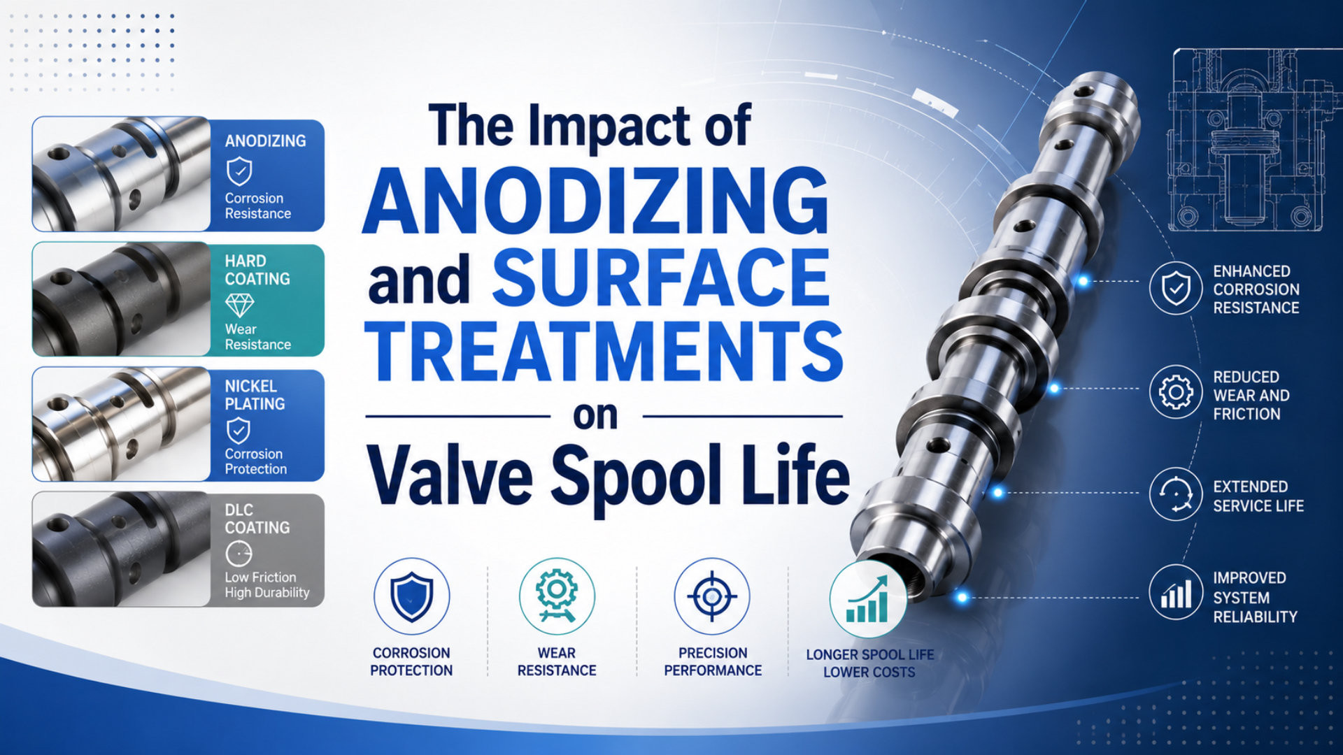
Anodizing can improve an aluminium valve spool’s resistance to abrasion and corrosion, but hardness alone doesn’t determine service life. Its complete sliding pair matters: materials, coating growth, finish, lubrication, contamination, alignment, and the clearance left after processing. Harder layers can protect the substrate while reducing that clearance enough to increase drag or sticking.
Key Takeaways
- ISO 10074:2021 treats hard anodizing as a specified coating and test system, not a universal life multiplier.
- Measure outward growth on both members before calculating final diametral clearance.
- Match the treatment to the failure mode, substrate, counterface, lubrication, and environment.
- Approve parts by dimensions, surface condition, and relevant tests, not colour or hardness alone.
Why Doesn’t a Harder Surface Guarantee Longer Valve Spool Life?
Researchers in 2020 examined hard-anodized 6061-T6 aluminium, one alloy under one laboratory test programme, rather than a population of pneumatic valves (Journal of Alloys and Compounds, 2020). Their study supports material-specific testing, but cannot establish a fixed multiplier for valve spool life.
Surface condition is only one part of the wear system. Spools can fail because particles score the lands, the pair runs with insufficient clearance, deposits create adhesive drag, a corrosive fluid attacks defects, or a misaligned operator pushes the spool against the bore. Valve spool life is the interval during which the moving element still meets its force, response, leakage, and dimensional requirements. Comparing spool and poppet designs shows why their sealing behaviour differs. Soft-sealed, lapped-metal, coated-aluminium, and sleeve-guided spools also create different contact conditions, so identify the construction before comparing finishes.
| Observed failure | Surface-related mechanism | Other causes to exclude first |
|---|---|---|
| Rising shift force | Roughness, transfer, deposits | Pilot pressure, spring, body distortion |
| Internal leakage | Wear, scoring, corrosion pits | Spool state, soft seal, test setup |
| Intermittent sticking | Tight clearance, edge buildup, debris | Voltage, pilot exhaust, manifold dirt |
| External corrosion | Coating discontinuity | Condensation, chemicals, galvanic contact |
| Uneven polish marks | Local contact | Bent operator, concentricity, assembly load |
Ask which failure mode the pair must resist without consuming its leakage and movement allowance. That connects material selection to valve function.
Anodizing Types Belong to Different Specification Families
ISO separates two jobs: ISO 7599:2018 covers decorative and protective anodic coatings, while ISO 10074:2021 covers hard anodic coatings used mainly for engineering wear and abrasion resistance (ISO 7599; ISO 10074). Type labels alone are therefore not a complete valve-spool specification.
General protective anodizing is not hard anodizing
General protective finishes fall under ISO 7599:2018, whose scope excludes hard, chromic-acid, and phosphoric-acid anodizing. Hard anodic coatings and customer-supplied process information fall under ISO 10074:2021. Valve drawings need masking, finished dimensions, texture, post-treatment, and inspection locations. Military Type I, II, and III labels likewise describe process families, not guaranteed thickness, hardness, friction, colour, or life. Include the document revision, class, thickness, post-treatment, masking, and tests.
Sealing is a functional choice
Sealing modifies pores and can improve selected protective properties, but it can also change abrasion behaviour or interfere with a later lubricant. ISO 3210:2025 describes two mass-loss methods for sealed anodic coatings, yet excludes hard-type coatings because they are normally unsealed. Specify the post-treatment required by the qualified system instead of copying a generic “sealed anodize” note. Food equipment needs more than “FDA-approved anodizing.” Verify the alloy, chemistry, topcoat, lubricant, cleaning chemicals, contact location, and applicable regulations.
How Does Coating Growth Change Spool-to-Bore Clearance?
Published in 2017, ISO 2360 specifies one non-destructive eddy-current method for measuring non-conductive coating thickness and notes that it applies to most anodic oxide coatings (ISO 2360, 2017). Thickness still isn’t the same as outward dimensional growth, so both values must be defined for a precision spool fit.
Let be the spool diameter before treatment, the bore diameter before treatment, the measured outward radial growth on the spool, and the measured inward radial growth on the bore. The finished diameters are:
The finished diametral clearance is:
Here, is the pre-treatment diametral clearance and is the finished diametral clearance. All dimensions must use the same units and the same temperature reference. and represent measured dimensional change, not an assumed fraction of total oxide thickness.
Consider with each member growing toward the gap by . Then . This calculation doesn’t declare that result acceptable; the valve designer sets the functional limit.
Edges, grooves, cross holes, threads, and mask transitions complicate the stack. Critical lands and metering edges need explicit drawing treatment instead of a blanket note that leaves the anodizer to guess.
With a coated spool-and-bore pair, release the finished functional gap or finished mating dimensions. Coating thickness is a process-control input, not a substitute for final geometry; two conforming coatings can still create an unacceptable clearance.
Which Surface Treatment Fits the Actual Failure Mode?
Norgren specifies one V44 glandless valve as a matched aluminium spool-and-sleeve pair that is hard anodized and Teflon coated, with compressed air filtered to 40 micrometres (IMI Norgren V44/V45 datasheet). That evidence supports a qualified pair, not an interchangeable coating recipe for every valve.
Matched-pair wording matters. Spool, sleeve, anodic layer, low-friction treatment, air quality, and manufacturing controls work together. Copying only “PTFE coated” onto another stack removes that context.
| Primary failure mode | Treatment direction to evaluate | Required qualification evidence | Common specification trap |
|---|---|---|---|
| Abrasive particles | Hard anodic coating on qualified aluminium | Wear, roughness, particle and mating-part tests | Assuming hardness prevents scoring |
| Adhesive transfer | Compatible low-friction system | Breakaway, cycling, transfer and lubricant tests | Treating a handbook coefficient as guaranteed |
| Corrosive moisture | Qualified anodic system and post-treatment | Alloy-specific corrosion and discontinuity tests | Claiming galvanic corrosion is eliminated |
| Chemical cleaning | Coating and seal system tested with the chemical | Concentration, temperature and exposure records | Calling a material universally resistant |
| Steel-spool wear | Qualified metallic, nitride, or DLC-type treatment | Adhesion, thickness, finish and cycle test | Applying aluminium rules to steel |
| Tight-clearance sticking | Correct the dimensional stack | Geometry, roughness and shift force | Adding thickness to a marginal fit |
Hard anodizing applies to aluminium and its alloys, and alloy composition affects the oxide. PTFE, electroless nickel, nitride, chromium, ceramic-like, and DLC-type treatments are unrelated processes whose results depend on the substrate, counterface, load, speed, temperature, and lubricant. If corrosion dominates, select an exposure test around the real environment. If contamination dominates, fix the air path. The control-valve contamination guide explains why hardness cannot compensate for water, residue, scale, or assembly debris.
Surface Finish, Sealing, and Lubrication Must Be Specified Together
Three abrasion methods appear in ISO 8251:2018: abrasive-wheel, abrasive-jet, and falling-sand tests; hard anodizing uses the first two through ISO 10074 (ISO 8251, 2018). None of those three tests alone reproduces a lubricated pneumatic spool moving inside its actual bore.
Hardness and friction are different properties. Hard surfaces can be rough, brittle at an edge, or incompatible with their counterface, so operating force may rise even when indentation hardness looks excellent. Specify texture after the processing stage that matters. Pre-anodize roughness doesn’t guarantee the finished land, and thickness readings don’t reveal raised edges, burns, cracks, abrasive, or lost roundness. Sealing and low-friction treatments must follow a qualified sequence because every seal, lubricant, impregnation, or post-finish changes sliding behaviour. Lubricated and non-lubricated duties also differ. Norgren approves its V44/V45 family for both, but that approval belongs to the complete model. Related unlubricated-air guidance covers lubrication, seals, and compressor by-products.
Treat friction as an assembly output. Measure breakaway and running force on the finished spool-and-bore pair at defined pressure, temperature, lubrication, and dwell time. Certificates can confirm the coating process, but cannot replace valve-level force and leakage tests.
What Should the Drawing and Purchase Specification Require?
Published in 2021, ISO 10074 includes coating requirements, test methods, and information the customer supplies to the anodizer (ISO 10074, 2021). Detailed valve-spool documents should therefore cover at least eight items: substrate, surfaces, dimensions, finish, masking, post-treatment, inspection, and traceability.
Write the specification so a supplier can manufacture and inspect the part without guessing:
- Identify the substrate. State grade, temper or heat treatment, and prohibited substitutions.
- Name the process. Give the standard, edition, type or grade, class, and qualified supplier process.
- Mark controlled surfaces. Identify lands, bore, metering edges, holes, threads, contacts, and masks.
- Control geometry. Specify finished diameters, clearance, roundness, straightness, edge condition, and measurement temperature.
- Control texture. State the finished roughness parameter, evaluation conditions, direction, and location.
- Define post-treatment. Specify sealing, impregnation, topcoat, lubricant, post-finish, or none.
- Set tests. Include growth, appearance, wear or corrosion where relevant, shift force, and leakage.
- Require traceability. Link process lot, records, rework limits, and matched-pair identity.
When controlling thickness, ISO 2360:2017 provides a non-destructive method for most anodic oxides on suitable substrates. Curvature, edge proximity, conductivity, calibration, and surface condition still matter. Narrow lands may need a validated fixture or another agreed method.
| Acceptance characteristic | Where to measure | Why it matters |
|---|---|---|
| Finished spool diameter | Each controlled land, at defined angular positions | Detects taper, ovality and excess outward growth |
| Finished bore diameter | Each guiding zone, away from unsupported edges | Confirms the mating member, not only the spool |
| Diametral clearance | Calculated from paired finished dimensions or measured assembly | Connects process results to movement and leakage |
| Surface texture | Finished sliding lands and bore | Controls contact, transfer and breakaway behaviour |
| Coating condition | Lands, edges, ports, mask transitions and contact points | Finds burns, chips, cracks, pits and raised edges |
| Shift force and leakage | Finished valve under defined air conditions | Verifies the functional result of the complete stack |
Don’t convert a salt-spray hour count into years of valve life. ISO 9227:2022 states that salt-spray tests are useful for detecting discontinuities and checking maintained quality, but are not intended to rank materials or predict long-term corrosion resistance. Define the test as a quality-control screen within a product specification.
How Do You Separate Coating Failure from Contamination or Misalignment?
Three main contaminant groups, particles, water, and oil, are classified by ISO 8573-1:2010 (ISO 8573-1, 2010). Norgren’s coated V44 spool pair separately specifies 40-micrometre filtration, showing why coating condition and supplied-air condition must be investigated together.
Start with the symptom and preserve evidence. Record voltage, pilot and supply pressures, exhaust condition, temperature, lubricant policy, air quality, and whether the fault follows dwell or high cycling. Document deposits and wear direction before cleaning. Related contamination-size failure analysis shows why particle effects depend on architecture and clearance, not only micron size. Filter ratings also don’t describe water, sticky oil products, seal fragments, or assembly debris.
Use the following diagnostic order:
- Confirm command, manual override, pilot supply, and exhaust.
- Measure shift pressure or force and leakage by valve state.
- Inspect manifold distortion, fastener torque, and alignment load.
- Sample deposits before cleaning and identify their type.
- Map wear around the circumference and along the stroke.
- Compare geometry, texture, and coating with release records.
- Compare affected and unaffected valves from the same lots.
For instance, uniform polishing differs from one-sided scoring. One-sided marks suggest eccentricity, bending, body distortion, or local buildup, while random axial scratches suggest contamination. Investigate moisture and oil separately. Separate coalescing-filter guidance explains aerosol removal, upstream protection, and drainage. Internally piloted valves also require the pilot-operated valve checks that separate insufficient shifting force from mechanical drag. Let evidence set the correction: cleanliness for particles, drying for water, alignment for one-sided contact, dimension control for insufficient clearance, and coating qualification for transfer or corrosion. Changing the finish without fixing the cause only resets the failure clock.
Valve Spool Anodizing and Surface Treatment FAQs
Three salt-spray procedures appear in ISO 9227:2022, which expressly warns against using them to predict long-term corrosion resistance (ISO 9227, 2022). These five FAQs apply the same discipline to thickness, sealing, repair, friction, and incoming inspection: use controlled measurements, not universal shortcuts.
Does anodizing always increase a valve spool’s diameter?
An anodic oxide develops partly within the aluminium substrate and partly beyond the original surface, but the usable outward growth depends on the alloy and qualified process. Measure the finished diameter or validated growth directly. When both spool and bore are coated, calculate both members because their dimensional changes consume the same running clearance.
Is thicker hard anodizing always better for spool life?
No. ISO 10074:2021 treats thickness as one specified characteristic within a larger coating system. More thickness may improve a selected wear requirement, but it can also consume clearance, change edge geometry, or produce an unsuitable surface condition. Choose thickness from the failure mode and prove the finished valve’s force and leakage.
Should a hard-anodized valve spool be sealed?
Not automatically. ISO 3210:2025 excludes hard-type anodic coatings from its two sealed-coating mass-loss methods because those hard coatings are normally unsealed. Qualified valves may instead use an impregnation, lubricant, topcoat, or other post-treatment. State the exact sequence and verify wear, corrosion, friction, and fluid compatibility together.
Can a damaged anodized spool be stripped and recoated?
Only through an approved repair route. Stripping can remove or attack base material, alter land diameter and edge geometry, and change the fit with a matched sleeve. Rework must define dimensional limits, stripping chemistry, reprocessing count, heat or chemical exposure, final inspection, and whether the original paired bore remains acceptable.
What should incoming inspection check besides coating thickness?
Check finished spool and bore diameters, roundness, straightness, surface texture, edge and mask transitions, visual defects, cleanliness, process-lot traceability, and the specified post-treatment. Then test assembled shift force and leakage under defined air conditions. ISO 2360:2017 thickness measurement is useful, but it cannot establish the complete functional fit.
Sources and technical references
- ISO 10074:2021, hard anodic coatings.
- ISO 7599:2018, decorative and protective anodizing.
- ISO 8251:2018, abrasion methods.
- ISO 2360:2017, eddy-current thickness measurement.
- ISO 3210:2025, sealed-coating assessment.
- ISO 9227:2022, salt-spray testing.
- ISO 8573-1:2010, compressed-air purity classes.
- Characteristics and tribological behavior of the hard anodized 6061-T6 Al alloy, Journal of Alloys and Compounds, 2020.
- IMI Norgren V44/V45 datasheet, matched hard-anodized and Teflon-coated aluminium spool-and-sleeve construction and air requirements.