

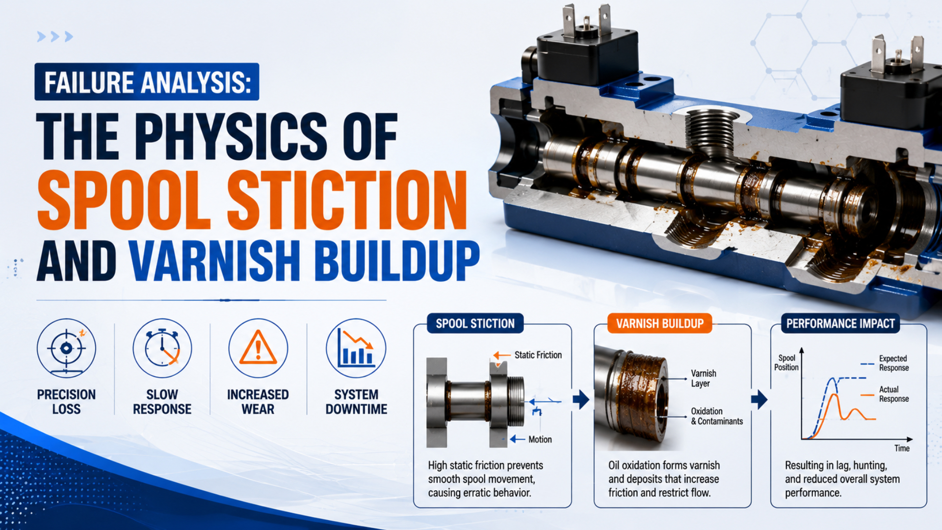
Spool valve stiction is the resistance that prevents a valve spool from beginning to move even though a valid command has been issued. It describes a mechanical symptom, not a proven deposit chemistry. The same slow or failed shift can result from low voltage, inadequate pilot pressure, blocked pilot exhaust, particles, water, swollen seals, degraded lubricant, scoring, or an organic deposit.
A defensible failure analysis therefore starts outside the valve. Record the command, coil voltage, manual-override result, dynamic supply and pilot pressures, exhaust condition, valve model, temperature, idle time, and air-treatment state before disassembly. Only call a deposit “varnish” when the system has a plausible organic source and the physical or laboratory evidence supports that conclusion.
TL;DR: ISO 8573-1 separates compressed-air purity into 3 contaminant groups: particles, water, and oil. Diagnose a sticking spool in the same disciplined way. Prove the electrical and pilot functions first, preserve the deposit evidence, and distinguish particle, moisture, lubricant, seal, and surface damage before selecting filtration, cleaning, or replacement.
What Does Spool Stiction Prove—and What Does It Not Prove?
SMC’s troubleshooting sheet checks at least 6 paths when a valve will not switch: power, operating pressure, pilot exhaust, foreign matter, silencer blockage, and actuator resistance (SMC Basic Pneumatic Circuit Troubleshooting, accessed 2026). A sticky response proves only that the commanded state was not reached normally.
Static friction is the force that must be overcome before sliding begins. Once the spool moves, running friction may be lower, so a contaminated or damaged valve can hesitate and then snap into position. That stick-slip signature is useful evidence, but it does not identify the material creating the resistance.
The word spool also covers different constructions. A clearance-sealed metal spool, an elastomer-sealed spool, a bonded-spool design, and a spool running in replaceable cartridges do not share the same contact interfaces. Some are intended to be serviced; many compact valves are not. Review the exact sectional drawing and maintenance instructions before assuming that metal lands are rubbing directly on a metal bore.
Use symptom language until the evidence becomes specific:
| Observation | What it establishes | What it does not establish |
|---|---|---|
| Coil indicator is on, but the valve does not shift | an electrical command may be present | rated voltage at the coil or main-spool movement |
| Manual override shifts the valve | the main pneumatic path can move under that test condition | healthy coil, wiring, connector, or PLC output |
| Valve shifts after supply pressure rises | force margin or pilot supply matters | contamination as the sole cause |
| Valve sticks after a long idle period | breakaway resistance is time-dependent | varnish chemistry |
| Brown or amber material is visible | a deposit exists | that the deposit is oxidized lubricant |
| Spool or bore has linear scratches | hard particles or assembly damage are plausible | the original particle source |
For the construction differences that change leakage and friction behavior, see the spool-versus-poppet valve guide. If the primary symptom is leakage rather than failed movement, use the separate internal valve leakage failure analysis.
Stiction belongs at the symptom level of a failure tree. Varnish belongs near the bottom, after the deposit source and composition have survived competing explanations.
How Should You Separate Electrical, Pilot, Exhaust, and Mechanical Causes?
One SMC VG300 troubleshooting table separates at least 6 paths—reduced pilot pressure, foreign matter, swollen O-rings, excessive lubrication, incomplete spool travel, and actuator leakage—instead of assigning every failed shift to contamination (SMC VG300 Operation Manual, accessed 2026). Follow that cause separation before opening a valve.
Start by defining the failed event. Record whether the problem occurs on energizing, de-energizing, both directions, one spool position, cold start, warm operation, or only after idle time. Note whether the outlet pressure changes slowly, not at all, or only after the valve is tapped or cycled. Avoid tapping during the first repeat because it destroys the original symptom.
Then test in an order that preserves evidence:
- Confirm the command. Measure voltage at the valve connector during the failed event, not only at the power supply. Check polarity, connector electronics, output-module capacity, wiring drop, and coil rating.
- Compare electrical and manual actuation. Use the manual override only when the machine’s approved procedure permits it. If the override works but the coil command does not, stay with the electrical or pilot stage.
- Measure dynamic pressure. Record supply pressure at the valve and separate pilot pressure where used. A static regulator gauge may hide a transient pressure collapse.
- Open the pilot exhaust path. A plugged PE port or clogged silencer can create back pressure that prevents a pilot stage from resetting. The silencer-clogging guide explains that competing failure mode.
- Separate valve and actuator behavior. Confirm whether the valve’s work-port pressure changes even when the cylinder does not move. Load, guide misalignment, flow-control settings, and cylinder friction can imitate a valve fault.
- Repeat under controlled conditions. Record pressure, voltage, temperature, state, idle duration, and timing for each repetition. Change one variable at a time.
The force boundary explains why low pilot pressure and contamination can produce the same symptom. For a pilot-operated main spool, a simplified screening relationship is:
Here, is the effective pilot-pressure difference in pascals, is effective pilot area in square metres, and the force terms are return, seal, deposit-related, and pressure-imbalance resistance in newtons. The relationship is diagnostic, not a universal sizing equation: geometry and force terms require manufacturer data or controlled measurement.
If pilot pressure is close to a model’s minimum, a clean valve may shift intermittently while a slightly contaminated valve stalls. For example, a pressure trace that collapses only during the failed shift directs the investigation upstream even when cycling later frees the spool. Raising pressure can restore motion without removing the root cause. Conversely, replacing the valve cannot correct a collapsing pilot supply. The internal pilot-pressure guide covers that boundary in more detail.
Evidence That Separates Particles, Water, Lubricant, and Seal Damage
ISO 8573-4 measures particle concentration by number but does not distinguish the sample’s 2 particle phases—solid and liquid (ISO 8573-4:2019, 2019). A particle result alone therefore cannot identify every residue seen inside a valve; location, morphology, materials, and contamination history still matter.
Before disturbing the valve, photograph its model code, port orientation, manifold position, connector, filter elements, bowls, drain condition, lubricator setting, and visible residue. Record whether neighboring valves on the same manifold share the problem. For example, one failed station suggests a local valve, load, or assembly issue; similar residue in several stations fed by the same gallery shifts attention upstream.
After applying the machine’s energy-control procedure and the valve manufacturer’s instructions, document the evidence without adding new contamination:
- Keep removed components, cartridges, seals, and samples identified by valve, station, port, orientation, and date.
- Use clean, compatible containers and tools specified by the investigation procedure. Do not wipe every surface before the residue has been photographed or sampled.
- Note whether deposits concentrate at the supply side, pilot stage, exhaust, seal contact, dead zone, or exposed ambient side.
- Examine filters and drains from upstream to downstream. A clean final filter does not exclude vapour, an exhausted element, a bypass, a damaged seal, or contamination added after the filter.
- Compare seal dimensions and hardness only with approved drawings and methods. Swelling, softening, cracking, flattening, and extrusion support different failure paths.
- Record scratches and burr direction. Long axial scoring is more consistent with hard debris or mechanical damage than with a soft surface film alone.
Visual appearance is not chemistry. Amber, brown, or glossy material may be compressor oil, lubricator oil, degraded grease, process aerosol, adhesive, cleaning residue, seal extractables, corrosion products mixed with oil, or a genuine oxidation-derived deposit. If the distinction controls a fleet-wide corrective action, send a representative sample to a qualified laboratory and provide unused lubricant, new seal material, compressor oil, and process-contaminant references for comparison.
SMC warns that excessive compressor carbon powder can adhere inside a valve and cause malfunction, while excessive drainage can also disrupt pneumatic equipment (SMC VFN Valve Precautions, accessed 2026). Those are separate mechanisms and demand different corrections.
A Defensible “Varnish” Diagnosis Requires an Evidence Chain
ASTM D7843-25e1 defines 1 membrane-patch colorimetry method for lubricant-generated insoluble colour bodies in in-service turbine oils; it is not a universal pneumatic-valve deposit test (ASTM D7843-25e1, 2025). The standard sets an important boundary: varnish terminology begins with an oil system and relevant analysis, not deposit colour alone.
In a pneumatic installation, an organic deposit hypothesis becomes stronger when several evidence layers agree:
- A credible source exists. Examples include oil carryover from an oil-flooded compressor, an upstream lubricator, unsuitable synthetic oil, process vapour entering the compressor intake, or a chemical aerosol introduced downstream.
- The transport path is credible. The deposit appears along the affected supply or pilot route, not randomly on an unrelated external surface.
- The operating pattern fits. Temperature, idle time, service history, lubricant changes, and affected stations correlate with the event without relying on a universal “temperature doubles reaction rate” rule.
- The residue is physically consistent. A tacky film, hard lacquer-like layer, or mixed oil-particle deposit is documented, while water, corrosion, assembly compound, and seal degradation are evaluated separately.
- Analysis or controlled comparison supports it. Laboratory spectroscopy, chromatography, thermal analysis, microscopy, or another suitable method links the residue to a source when the decision justifies the cost.
ISO 8573-5:2025 specifies measurement of oil vapour and certain organic solvents in compressed air using pressurized sampling and gas chromatography (ISO 8573-5:2025, 2025). That scope is narrower than “all oil”: liquid oil, oil aerosol, and wall deposits require appropriate methods and sampling locations.
The strongest varnish diagnosis connects four maps: what entered the air, how it travelled, where it deposited, and what the residue contains. Missing one map leaves an alternative cause open.
For upstream source analysis, use the oil-carryover guide. It separates compressor carryover from the much broader claim that every oily-looking valve deposit is oxidized lubricant.
How Do Deposits and Lubrication Changes Raise Breakaway Resistance?
Festo describes a 2-state lubrication boundary: once certain pneumatic valves have operated with lubricated compressed air, continued lubrication is essential because the added oil can flush away factory-applied basic lubrication (Festo Operating Conditions and Standards in Pneumatics, accessed 2026). Both excess and interrupted lubricant supply can change spool friction.
A deposit can raise breakaway resistance through more than one path. A soft film can increase viscous drag or make surfaces tacky during idle time. Particles can bridge a running clearance, embed in an elastomer, or score the bore. Dried grease can restrict a pilot element. Swollen seals can increase contact force. Corrosion can roughen a sliding surface or produce debris. These mechanisms can coexist.
Temperature and dwell time still matter, but the source article’s universal multipliers are not defensible. A warmer valve may reduce lubricant viscosity while accelerating some degradation reactions; a cold valve may stiffen grease or seals. Long dwell can allow squeeze-film drainage, adhesive contact, curing, corrosion, or deposit hardening. The direction and magnitude depend on the exact material system.
Use a controlled response test to characterize the symptom:
- Measure command-to-port-pressure time in both directions.
- Separate cold start, stabilized temperature, short dwell, and long dwell.
- Record dynamic supply and pilot pressure, coil voltage, exhaust arrangement, and cycle rate.
- Repeat enough events to show spread, not only an average.
- Compare with an unused or known-good valve of the same complete code under the same circuit.
Cycling can temporarily free a sticking element, but that does not prove self-repair. It may redistribute debris, restore a lubricant film, or wear through a deposit while leaving damage behind. A “works after ten cycles” observation belongs in the failure record and corrective-action verification, not in an acceptance statement.
The unlubricated-air effects guide explains why “dry air” and “never add oil” are still model-specific decisions rather than universal maintenance rules.
Air-Quality Specification After a Stiction Failure
ISO 8573-1:2010 defines compressed-air purity classes for particles, water, and oil, while individual equipment suppliers specify which class and operating conditions their product requires (ISO 8573-1:2010, 2010). Do not copy one valve’s class into a plant-wide specification without checking every affected product and process.
Start with the exact valve and pilot-stage data sheets. Record the required particle class or filter rating, pressure dew point or water limit, total oil class, permitted lubricant, minimum pressure, temperature range, and whether lubricated operation is allowed. If the main valve and pilot valve have different supplies, document both.
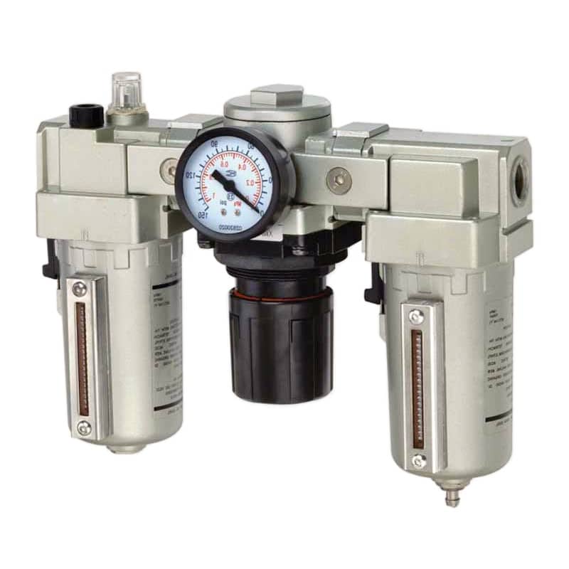
An FRL assembly illustrates three different functions. Its presence does not prove that the delivered air meets the valve’s required particle, water, or oil class; element grade, drain operation, flow, pressure drop, location, and lubricant setting still require verification.
Treat the air-treatment train as a set of measured functions:
| Contaminant or condition | Evidence to collect | Corrective-action direction |
|---|---|---|
| Solid particles | filter grade and condition, downstream particle result, pipe debris, scoring | source cleanup, suitable filtration, pipe flushing under approved procedure |
| Liquid water | drain history, bowl condition, low-point accumulation, aftercooler and separator state | repair separation and drains; prevent liquid carryover |
| Water vapour | pressure dew point at a defined pressure and sampling point | size and maintain the appropriate dryer |
| Oil aerosol | compressor and lubricator history, coalescing stage, downstream sampling | control source and aerosol removal |
| Oil vapour or organic solvent | compressor intake exposure, process vapours, suitable analytical sampling | source isolation and adsorption where required |
| Excess or interrupted lubrication | valve approval, oil type, lubricator rate, change history | restore the exact manufacturer-approved lubrication policy |
Relative humidity in the room is not a substitute for pressure dew point in the compressed-air line. Sampling location matters as well: a compliant result at the compressor room does not prove cleanliness after a corroded receiver, contaminated branch, failed lubricator, or process connection.
For an ISO-focused specification workflow, see the compressed-air quality standards guide. Use the valve manual as the acceptance requirement and the ISO methods as the common language for measuring it.
When Should a Valve Be Cleaned, Repaired, or Replaced?
OSHA 29 CFR 1910.147 lists 4 treatments for hazardous stored or residual energy under its servicing scope: relieve, disconnect, restrain, or otherwise render it safe (OSHA 1910.147, accessed 2026). A de-energized coil does not by itself control trapped air, suspended loads, springs, vacuum, or another pressure source.
Use the machine’s approved energy-control procedure and the exact valve manual. Some diagnostic tests require controlled energization; those tests need a separate documented method, rated fixtures, guarding, exclusion controls, suitable instruments, and authorized personnel. Do not loosen fittings, remove a spool, or apply solvent to a pressurized assembly.
Choose the disposition from the product’s serviceability and the evidence:
- Clean only when authorized. Use the named fluid, method, parts, lubricant, cleanliness level, and reassembly checks in the manufacturer procedure. “Solvent compatible with metal” is not enough; seals, adhesives, coatings, grease, plastics, and electronics also matter.
- Repair with approved parts. Replace the specified cartridge, seal kit, pilot assembly, coil, gasket, or silencer when the manual provides the procedure and inspection criteria.
- Replace the complete valve when necessary. Sealed miniature valves, damaged bores, deep scoring, corroded lands, lost coatings, uncertain clearances, and repeat failures after approved service commonly justify replacement.
- Escalate systemic evidence. Similar residue across multiple stations or manifolds requires an upstream investigation before new valves are installed.
Generic ultrasonic cleaning, aggressive solvent flushing, honing, polishing, lapping, or recoating can change clearances, remove surface treatments, damage elastomers, and eliminate factory lubrication. A valve that moves freely on the bench is not automatically safe or within leakage and switching specifications after such work.
Verify the result with the same valve function, pressure, voltage, temperature, dwell, exhaust arrangement, and measurement endpoints used to document the fault. Include leakage and both shift directions where applicable. If the corrective action changes the filter, dryer, lubricant, or valve design, define a follow-up interval that can confirm whether the deposit returns.
What Should a Failure Report and Replacement RFQ Contain?
SMC’s troubleshooting worksheet separates valve, pilot, silencer, tubing, speed controller, cylinder, guide, and sensor checks within one basic pneumatic circuit (SMC Basic Pneumatic Circuit Troubleshooting, accessed 2026). A useful failure report preserves the same system context instead of shipping an unlabelled valve to the supplier.
Include these fields:
- Machine, circuit, manifold station, valve manufacturer, full model code, serial or lot, and installation date.
- Valve function, normal state, actuation type, pilot arrangement, connector, coil voltage, suppression, and duty cycle.
- Supply, pilot, work-port, and exhaust pressure during the event; air temperature and relevant ambient conditions.
- Air-treatment layout, element grades, pressure dew point or other test results, drain history, lubricator status, lubricant identity, and recent changes.
- Symptom direction, command state, manual-override result, idle duration, response-time trace, leakage observation, recurrence frequency, and affected population.
- Photographs before cleaning, deposit and damage location, retained samples, seal condition, filter debris, and laboratory results where obtained.
- Every diagnostic change, its timestamp, and the result. Separate temporary symptom recovery from permanent corrective action.
- Required replacement envelope: port pattern, flow, pressure, temperature, leakage, switching time, media quality, electrical interface, approvals, and environmental protection.
A replacement valve code closes a purchase order. A cause-and-evidence record prevents the same contamination path from closing the next valve.
For a broader field sequence, see how to troubleshoot a failing pneumatic solenoid valve. When requesting engineering review, attach the circuit, measurements, photographs, air-quality requirement, and complete valve code through the contact page.
Spool Stiction FAQs: What Should Maintenance Teams Verify?
ISO 8573-1 defines 3 compressed-air contaminant groups, but a failed valve investigation also has to separate the electrical command, pilot path, exhaust, actuator load, seals, lubricant, and mechanical condition. These answers keep “stiction” as a measured symptom until the evidence supports a specific cause.
Can a New Pneumatic Valve Suffer from Stiction?
Yes. A new valve can fail to shift because of installation debris, seal incompatibility, incorrect lubricant, storage corrosion, distorted mounting, inadequate pilot pressure, blocked exhaust, wrong voltage, or manufacturing damage. Verify the circuit and model requirements before assuming normal break-in. Preserve the valve and contamination evidence for supplier review.
Does Brown Residue Prove That the Valve Contains Varnish?
No. Brown residue may contain compressor oil, lubricator oil, degraded grease, process aerosol, corrosion products, seal material, cleaning residue, or particles held in oil. A varnish diagnosis needs a credible organic source, a matching transport path, documented deposit location, and analytical or controlled comparative evidence appropriate to the corrective-action decision.
Can Repeated Cycling Permanently Fix a Sticking Spool?
Not reliably. Cycling may redistribute particles, restore a lubricant film, wear through a deposit, or temporarily overcome higher breakaway friction. Record the number of cycles and response change, but do not treat symptom recovery as proof of removal. Repeat the original test after a defined dwell and inspect the root cause.
Should a Sticking Pneumatic Valve Be Flushed with Solvent?
Only when the exact manufacturer procedure authorizes the solvent and method for that complete valve code. An unapproved solvent can swell seals, dissolve grease, attack adhesives or plastics, remove coatings, and carry debris into smaller passages. If the valve is sealed or the clearance is damaged, controlled replacement is usually safer than improvised restoration.
Which Air-Quality Number Prevents Every Stiction Failure?
There is no universal class. ISO 8573-1 classifies particles, water, and oil, but the required limits come from the exact valve, pilot stage, process, and reliability target. Air quality also cannot correct low voltage, blocked exhaust, misassembly, swollen seals, scoring, or insufficient pilot pressure. Specify and verify each failure path separately.
Sources and Technical References
This analysis uses 9 primary standards, manufacturer documents, and regulatory sources covering compressed-air contamination, valve troubleshooting, lubricant deposits, and hazardous-energy control. Product precautions illustrate evidence paths; they do not create universal limits for every spool construction.
Publisher and author information is available on About Us. Submit technical corrections or application evidence through the contact page with the exact valve code, circuit state, measured pressures, voltage, air-quality requirement, and photographs.
- ISO 8573-1:2010, Compressed air — Part 1: Contaminants and purity classes. Retrieved 2026-07-22.
- ISO 8573-4:2019, Test methods for particle content. Retrieved 2026-07-22.
- ISO 8573-5:2025, Test methods for oil vapour and organic solvent content. Retrieved 2026-07-22.
- SMC, Basic Pneumatic Circuit Troubleshooting Check Sheet. Retrieved 2026-07-22.
- SMC VG300 Series Operation Manual and Troubleshooting. Retrieved 2026-07-22.
- SMC VFN NAMUR Interface Solenoid Valve Precautions. Retrieved 2026-07-22.
- Festo, Operating Conditions and Standards in Pneumatics. Retrieved 2026-07-22.
- ASTM D7843-25e1, Measurement of Lubricant Generated Insoluble Color Bodies in In-Service Turbine Oils. Retrieved 2026-07-22.
- OSHA 29 CFR 1910.147, The Control of Hazardous Energy. Retrieved 2026-07-22.