

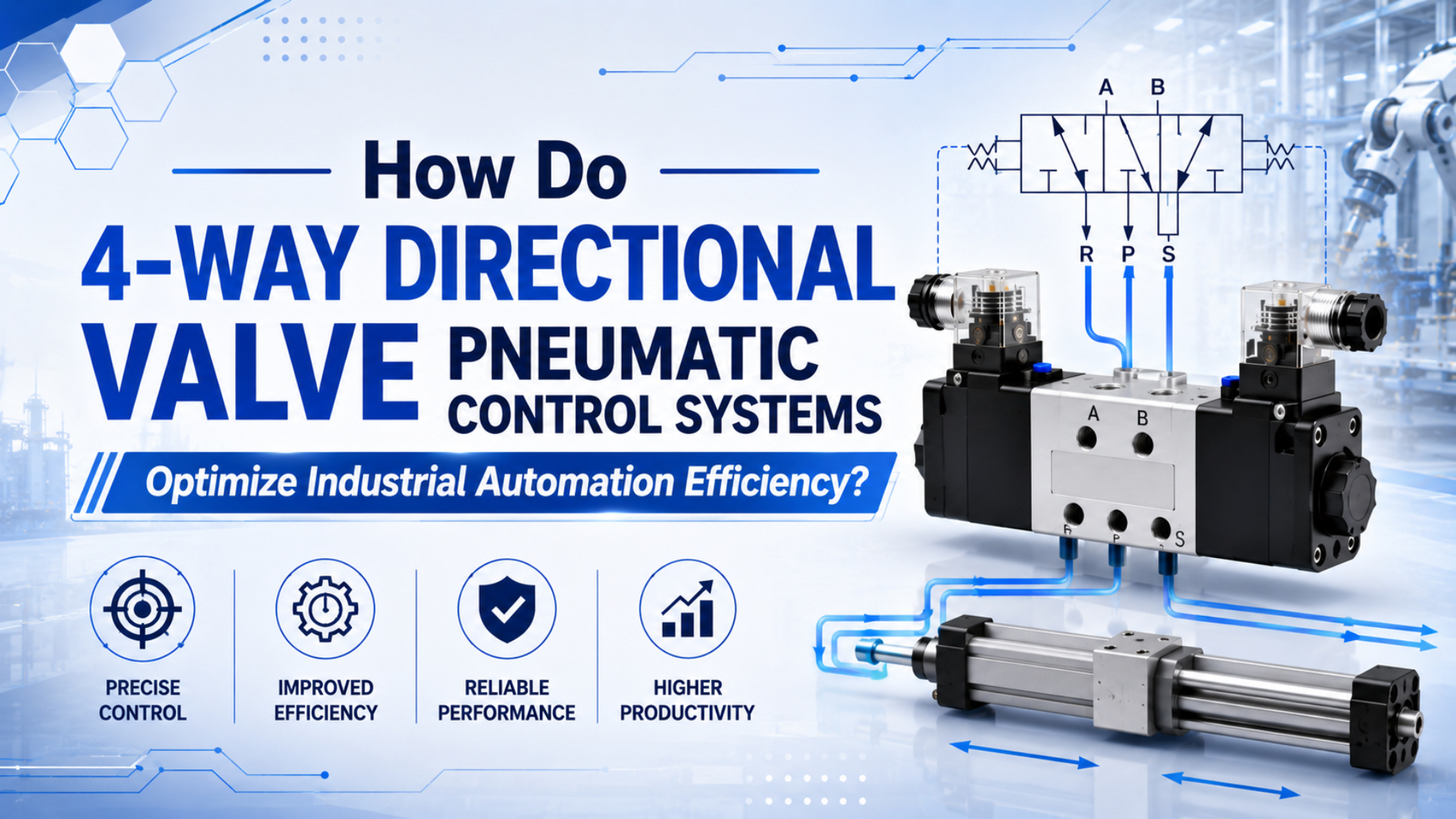
4-way directional valve pneumatic control systems optimize industrial automation by matching valve function, flow capacity, exhaust control, and electrical command timing to the actuator’s required motion. Tameson identifies 4/2, 5/2, and 5/3 valves as common double-acting cylinder control choices, while CAGI recommends keeping compressed-air pressure drop within 10 percent from compressor discharge to point of use (Tameson, 2024; CAGI, 2022).
The short version is practical: the valve doesn’t only reverse a cylinder. It decides whether a machine axis reaches speed, stops safely, exhausts cleanly, and repeats the same motion when the line is hot, dusty, wet, or running at peak demand.
Directional control valve is a pneumatic component that changes which air passages are connected, so compressed air can start, stop, reverse, exhaust, or hold an actuator circuit.
Valve Cv is a flow-capacity rating used to compare whether a valve path can pass enough air for the required actuator stroke time and pressure drop.
Key Takeaways
- A 4-way directional valve control system improves automation efficiency when valve function, Cv, tubing, exhaust, coil voltage, and PLC logic are selected together.
- Parker’s sizing example shows a 3.25 inch bore cylinder, 12 inch stroke, 1 second stroke time, and 80 psi supply requiring Cv 1.06.
- CAGI’s 10 percent pressure-drop target is a useful line-side check before blaming the valve.
In our experience, the field mistake is treating a directional valve as a simple on/off electrical part. The coil may shift correctly while the axis still misses time because the exhaust side is restricted, the manifold supply drops during simultaneous demand, or the valve function doesn’t match the machine’s pause and fault behavior.
Use valve function, supply pressure, exhaust capacity, manifold sizing, and fault behavior together when reviewing directional-valve performance.
What Does a 4-Way Directional Valve Control System Actually Optimize?
A 4-way directional valve control system optimizes 4 linked jobs: direction, speed, repeatability, and fault behavior. Tameson describes directional valves as components that control start, stop, direction, and speed of cylinder piston movement, while CAGI’s 10 percent pressure-drop target keeps the valve decision tied to the whole air system (Tameson, 2024; CAGI, 2022).
The valve sits between the controller and the actuator, so it has to satisfy both worlds. Electrically, the PLC expects a predictable command response. Pneumatically, the actuator needs enough air into one chamber and enough exhaust out of the opposite chamber. Miss either side and the motion gets slow, noisy, or inconsistent.
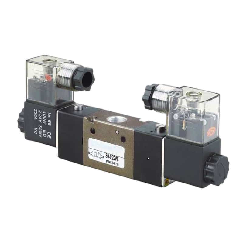
Think of the system as 6 checks:
| Control check | What it protects | What happens when it is wrong |
|---|---|---|
| Valve function | correct extend, retract, stop, or hold behavior | wrong motion during pause or fault |
| Cv and flow path | stroke time and peak demand | slow axis, missed sensor, pressure sag |
| Exhaust path | stable speed and low back pressure | one direction slower than the other |
| Coil or pilot command | PLC timing and repeatability | delayed shift or intermittent motion |
| Air quality | spool and seal reliability | sticking, leakage, weak return |
| Safety state | maintenance and restart risk | stored-energy or unexpected-startup hazard |
When troubleshooting an automation cell, we usually don’t start with “replace the valve.” We first ask whether the machine problem is directional, flow-related, electrical, exhaust-related, or safety-state related. That one split prevents a lot of expensive guessing.
How Should You Choose Between 4/2, 4/3, 5/2, and 5/3 Valves?
Choose the valve function from the required actuator behavior, not from habit. Tameson lists 4/2, 5/2, and 5/3 valves for double-acting pneumatic cylinder control, with 5/2 offering 2 positions and separate exhaust paths and 5/3 adding a center position for more control (Tameson, 2024).
A 4/2 valve can run a basic double-acting actuator when the circuit only needs extend and retract. It has fewer paths to manage, but it doesn’t give the same separate exhaust tuning that a 5-port layout provides.
A 5/2 valve is the normal workhorse for double-acting cylinders. It has one pressure supply, two working ports, and two exhaust ports. Need the port-by-port detail for a rodless cylinder? Use the focused guide on 4-way 5-port pneumatic valve control for rodless cylinders.
A 4/3 or 5/3 valve is for the center condition. What should the actuator do when the command stops, the operator pauses the cell, or the PLC enters a fault routine? Center closed, center exhaust, and center pressure functions can behave very differently.
| Valve function | Positions | Best fit | Main caution |
|---|---|---|---|
| 4/2 | 2 | simple double-acting extend/retract | less exhaust-side flexibility |
| 4/3 | 3 | basic motion with center-state requirement | center condition must match the load |
| 5/2 | 2 | most double-acting automation axes | exhaust path still needs sizing |
| 5/3 | 3 | pause, hold, or controlled fault-state behavior | not all center types are safe for every load |
The decision starts with behavior. Does the axis only reverse? Use 5/2 in many cases. Does it need a defined center state? Move to 5/3 and document that center state in the RFQ.
How Do Cv, Tubing, and Exhaust Paths Set Cycle Time?
Cycle time depends on the full flow path, not only the valve port thread. Parker’s valve-sizing example calculates Cv 1.06 for a 3.25 inch bore cylinder with a 12 inch stroke, 1 second stroke time, and 80 psi supply, then says any valve with at least that Cv can extend the cylinder in the required time (Parker, 2026).
That example gives the right selection order:
- Define bore, stroke, load, working pressure, and target stroke time.
- Estimate the required air flow for the actuator.
- Convert the motion requirement into valve capacity.
- Check tubing, fittings, mufflers, regulators, and manifolds.
- Test both supply and exhaust sides under real cycle demand.
SMC gives the speed relationship as s = 28.8q / A, where s is cylinder speed in inches per second, q is airflow in SCFM, and A is piston area in square inches, with inlet pressure held constant (SMC, 2026). That sentence carries a quiet warning: pressure must stay stable while the machine moves.
Don’t ignore the exhaust side. SMC says the common industry practice for pneumatic actuator speed control is to control flow at the actuator’s exhaust port with meter-out flow control or a needle valve (SMC, 2026). If that path is too tight, one direction may crawl even while the pressure gauge looks normal.
Why Do Good Valves Still Make Machines Slow or Inconsistent?
Good valves still create slow motion when the surrounding pneumatic circuit makes them operate outside the real demand window. CAGI says pressure drop comes from friction and resistance in piping, fittings, filters, dryers, and other components, and recommends no more than 10 percent drop from compressor discharge to point of use (CAGI, 2022).
That is why a bench-tested valve can disappoint after installation. On the bench, it may shift cleanly. On the machine, the same valve shares a manifold, feeds long tubes, exhausts through compact mufflers, and runs during a peak-demand moment when other axes are moving.
Use this failure map before buying the next size up:
| Symptom | Likely valve-system cause | First check |
|---|---|---|
| Slow in both directions | undersized supply, low point-of-use pressure, small manifold | measure pressure at the valve during motion |
| Slow in one direction | restricted exhaust, crossed speed controller, blocked muffler | compare EA and EB exhaust paths |
| Good first cycle, weak repeated cycles | receiver or branch line can’t recover | check pressure sag across repeated strokes |
| Valve shifts, cylinder doesn’t move | blocked actuator port, wrong function, no pilot pressure | verify port map and pilot supply |
| Jerky motion near end stroke | exhaust too restricted or load changes | tune meter-out and cushioning together |
| Axis drifts during pause | wrong center condition or internal leakage | review 5/3 center type and load forces |
For deeper diagnostics, the related guides on pressure drop in pneumatic systems and back pressure are better next reads than a generic valve catalog.
The fastest practical test is often a dynamic pressure check. Measure supply pressure at the valve while the actuator moves, not while the machine is idle. Idle pressure can hide the exact restriction that shows up during the stroke.
Which Actuation Method Fits an Automated Machine?
Actuation method should match the control architecture, available signal energy, flow requirement, and manual-intervention plan. Parker’s catalog groups valve choices across solenoid, manual or mechanical, air pilot, and direct or pilot-operated designs, with listed Cv ranges varying from tiny 0.01 class valves to high-flow series above Cv 10 (Parker, 2026).
For PLC automation, solenoid-operated or solenoid-pilot valves are the normal starting point. Direct-acting solenoid valves are useful when the flow is small and the response needs to be simple. Pilot-operated valves make more sense when the main air path needs more flow than the coil can practically shift directly.
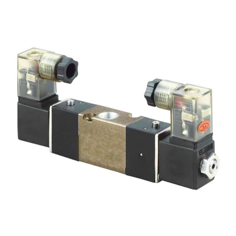
| Actuation method | Use it when | Watch closely |
|---|---|---|
| Direct solenoid | compact valves, low-flow circuits, simple PLC output | coil voltage, heat, flow limit |
| Solenoid pilot | automated machinery with larger actuator demand | minimum pilot pressure and response lag |
| Air pilot | pneumatic logic, hazardous electrical areas, remote air signals | pilot line delay and pressure stability |
| Manual or mechanical | setup, fixture control, maintenance jog, operator stations | safe position, guarding, and restart rules |
| Fieldbus valve island | many nearby valves need fewer wire runs | network diagnostics and spare address plan |
Need a narrower solenoid article? Read how pneumatic solenoid valves work. Need the pilot-stage detail? Read pneumatic pilot-operated valves.
The important RFQ question is not “solenoid or pilot?” It is: what signal shifts the valve, what air pressure lets it shift, what flow does the actuator require, and what should the valve do when that signal disappears?
What Should the PLC and Safety Design Check Before Startup?
Safety design must account for stored pneumatic energy, not only electrical power. OSHA 29 CFR 1910.147 covers servicing and maintenance where unexpected startup or release of stored energy could injure employees, and defines pneumatic energy as one energy source under the standard (OSHA, 2026).
That doesn’t mean a directional valve alone is a safety system. It means the valve selection has to support the machine’s safety concept. A valve center condition, lockout valve, dump valve, pressure switch, sensor feedback, and restart procedure may all be involved.
Check these items before startup:
| Startup check | Why it matters |
|---|---|
| De-energized valve state | proves what the actuator does after power loss |
| Center position behavior | determines hold, exhaust, or blocked-port response |
| Exhaust and dump path | controls how stored air leaves the circuit |
| Sensor confirmation | proves the actuator reached the expected end state |
| Manual override policy | avoids hidden movement during setup |
| Lockout procedure | separates maintenance safety from normal PLC logic |
OSHA also states that push buttons, selector switches, and other control-circuit devices are not energy-isolating devices (OSHA, 2026). That’s a useful reminder for pneumatic panels: an HMI stop command is not the same as isolating stored air for maintenance.
How Do You Specify a 4-Way Directional Valve for an RFQ?
A useful RFQ gives the supplier enough data to select function, Cv, porting, actuation, and accessories together. Parker’s selection sequence moves from required Cv to valve series, port size, flow-path configuration, actuation method, model number, options, and accessories (Parker, 2026).
Send the operating data, not just a photo of the failed valve. A photo helps with mounting and connector style, but it doesn’t prove whether the original valve was correctly sized.
| RFQ field | What to provide |
|---|---|
| Actuator type | double-acting cylinder, rodless cylinder, rotary actuator, gripper, or fixture |
| Bore, stroke, and load | dimensions, payload, mounting direction, and required motion |
| Target cycle time | extend time, retract time, dwell time, cycles per minute |
| Working pressure | normal pressure, minimum pressure during motion, regulator setting |
| Valve function | 4/2, 4/3, 5/2, 5/3, and preferred center condition |
| Flow data | required SCFM, L/min, Cv, Kv, or catalog flow rating |
| Electrical data | voltage, AC/DC, connector type, PLC output limit |
| Pneumatic connection | port thread, tube OD, manifold type, muffler, speed controller |
| Environment | temperature, moisture, washdown, dust, oil mist, vibration |
| Safety state | behavior after power loss, E-stop, and maintenance isolation |
For product-family context, the 200 Series pneumatic directional control valves page is a useful reference for solenoid and air-actuated directional-valve options. The 100 Series pneumatic directional control valves page helps when compact valve assemblies are the better fit.
FAQs About 4-Way Directional Valve Pneumatic Control Systems
Is a 4-way directional valve the same as a 5/2 valve?
Not always. In common pneumatic usage, a “4-way” valve often describes the directional function for a double-acting actuator, while “5/2” describes 5 physical ports and 2 spool positions. Tameson lists 5/2 valves as common for double-acting cylinders with separate exhaust paths (Tameson, 2024).
What is the most important sizing variable for a 4-way valve?
The most important sizing variable is required flow at the target stroke time, then valve Cv or equivalent flow data. Parker’s example calculates Cv 1.06 for a 3.25 inch bore, 12 inch stroke, 1 second stroke time, and 80 psi supply, showing why port size alone is not enough (Parker, 2026).
Why is one cylinder direction slower than the other?
One direction is often slower because the exhaust path is more restricted than the supply path. SMC notes that cylinder speed is commonly controlled at the actuator’s exhaust port with meter-out flow control or a needle valve, so a blocked muffler, tight speed controller, or small exhaust path can slow only one direction (SMC, 2026).
Should I use a 5/3 valve instead of a 5/2 valve?
Use a 5/3 valve when the machine needs a defined center condition during pause, fault, or loss of command. Tameson describes 5/3 valves as adding a center position for more control, including stopping or holding behavior. The right center condition depends on the load, actuator, safety design, and restart procedure.
Can I fix slow automation by increasing compressor pressure?
Usually, check pressure drop first. CAGI says raising compressor discharge pressure or adding a compressor can be costly and should not be the first step for excessive pressure drop. Measure point-of-use pressure during motion, then inspect tubing, fittings, filters, dryers, manifolds, leaks, and exhaust restrictions before changing compressor settings (CAGI, 2022).
Sources and Further Reading
Use source-backed valve-function, Cv-sizing, pressure-drop, speed-control, and hazardous-energy references instead of unsupported productivity, response-time, ROI, or reject-rate claims.
- Tameson, Directional Control Valves in Pneumatic Systems, valve function, 4/2, 5/2, and 5/3 configuration guidance. Retrieved 2026-07-08.
- CAGI Pressure Drop Technical Brief, 10 percent pressure-drop target and pressure-loss causes in compressed-air systems. Retrieved 2026-07-08.
- Parker 0600P Pneumatic Valve Catalog Introduction, valve selector chart, Cv ranges, and cylinder stroke-time sizing example. Retrieved 2026-07-08.
- SMC, Control Air Flow of Cylinders, cylinder speed equation and meter-out speed-control guidance. Retrieved 2026-07-08.
- OSHA 29 CFR 1910.147, hazardous-energy control scope and pneumatic energy definition. Retrieved 2026-07-08.