

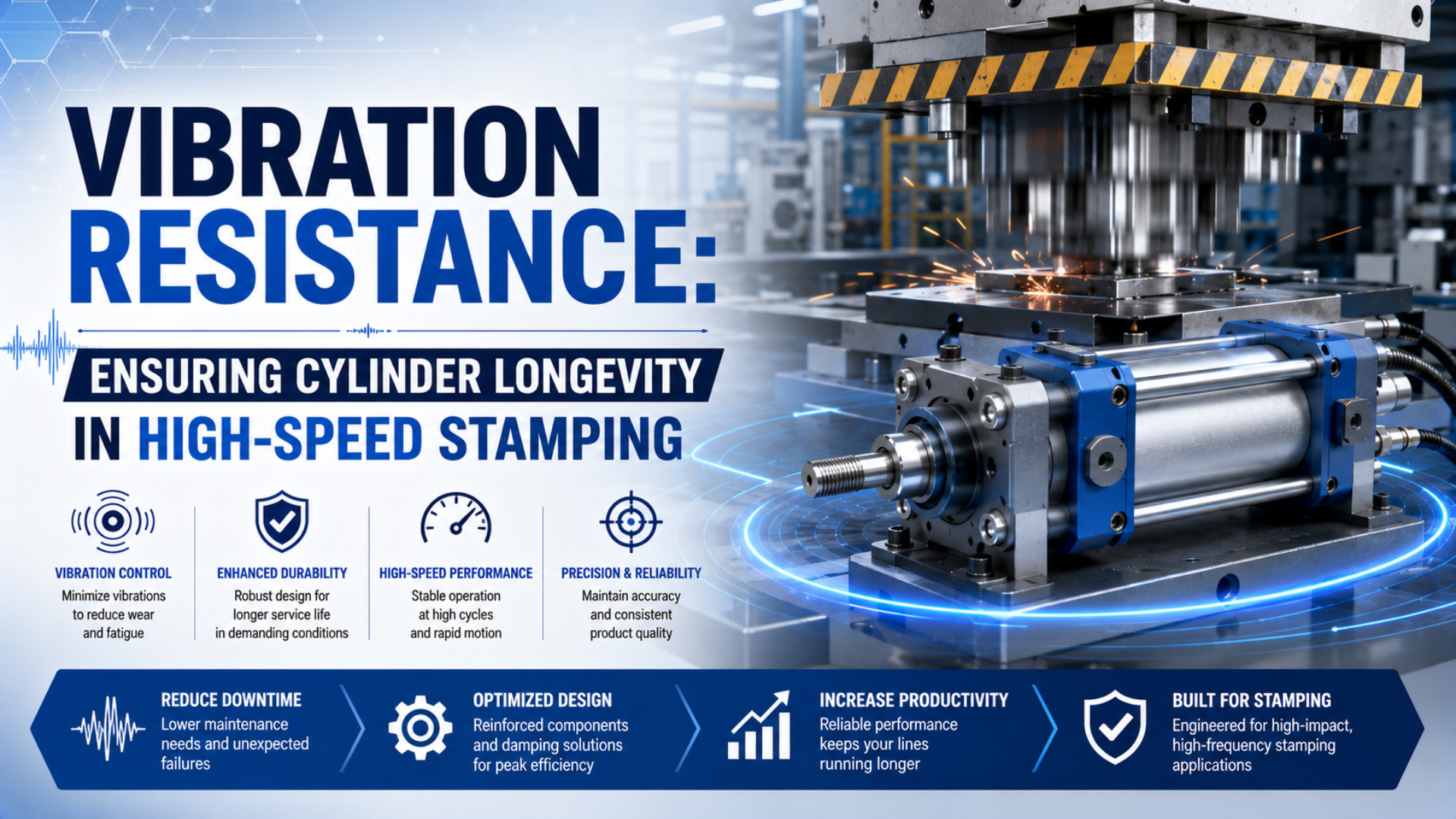
Pneumatic cylinder life on a high-speed stamping press is not determined by an undefined “vibration-resistant” label. It depends on the measured machine input, the response at the cylinder mount, the actuator’s own motion and stopping loads, the mounting load path, and the acceptance limits for the exact installed configuration.
At 450 strokes per minute, the stamping event repeats at 7.5 Hz. That number is only the event rate. Each impact can excite harmonics, local bracket modes, and broadband structural response at much higher frequencies. Selecting a cylinder from strokes per minute alone leaves the damaging part of the environment undefined and can hide a damaging local resonance.
That distinction changes the diagnosis.
Key Takeaways
- A press running at 450 strokes/min has a 7.5 Hz event rate, not a complete vibration spectrum.
- Measure the press frame and cylinder mount with synchronized channels under the same production recipe; local response can exceed the base input near resonance.
- Separate frame vibration from actuator-generated loads.
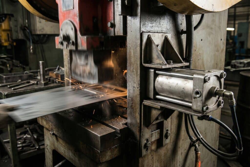
A cylinder mounted near a press working area shares the machine’s structural environment. The image shows installation context, not evidence of a vibration rating.
Why Does Stroke Rate Not Equal Vibration Frequency?
IEC uses separate methods for sinusoidal vibration, shock, and broadband random vibration, so strokes per minute cannot stand in for an installed vibration specification (IEC 60068-2-6, 2007; IEC 60068-2-27, 2008; IEC 60068-2-64, 2008). A 450-stroke/min press repeats the event at 7.5 Hz, while each impact can excite a wider spectrum.
Convert press speed into the fundamental event rate with:
In this equation, is the event rate in hertz and is press speed in strokes per minute. It assumes one stamping event per press stroke. A 600-stroke/min recipe therefore has a 10 Hz event rate. That result establishes timing, but it cannot prove that the cylinder experiences only 10 Hz motion or define the amplitude of any structural response.
Impact waveform, press-frame stiffness, die condition, mounting plate, fasteners, cylinder mass, attached tubing, and sensor brackets all influence the installed response. Local bracket response can peak far above the event rate. Joint looseness can also create impacts that were absent from the original baseline.
The useful distinction is between event rate and response spectrum. Event rate comes from the production recipe. Response spectrum comes from measurement. Treating them as the same quantity can send a maintenance team toward a different seal compound when the real problem is a resonant bracket or shifting joint.
Dynamic Loads Reaching the Cylinder
NIST defines standard gravity as exactly 9.80665 m/s², but acceleration becomes a component load only after mass and load path are included (NIST Guide to the SI, retrieved 2026-07-26). A complete review separates four load cases rather than combining them under one G value.
- Base vibration and press shock enter through the machine frame, mounting plate, fasteners, fittings, tubing, and sensor brackets. They can act while the piston is stationary.
- Commanded moving-load inertia comes from accelerating and decelerating tooling or a transfer device. It belongs in the thrust, guide-force, moment, and frame checks.
- End-of-stroke stopping occurs when moving mass is brought to rest by a bumper, pneumatic cushion, external shock absorber, or mechanical stop.
- Process and alignment loads include side force, offset moment, rod binding, carriage moment, hose drag, and distortion of the mounting surface.
Mass changes every reaction.
For a simple rigid-body screening calculation, convert an acceleration stated in multiples of standard gravity:
Acceleration is in m/s², is the measured or specified multiple of standard gravity, and is 9.80665 m/s². Then estimate the inertial reaction:
Force is in newtons and is the participating mass in kilograms. Include the cylinder, mount, tooling, sensors, manifolds, and supported accessories that react through the checked interface. These equations do not include resonance, joint slip, local flexibility, or impact contact, so they are screening tools rather than product ratings. For example, a 20 kg participating mass under a simplified 10 g input produces an inertial-force magnitude of about 1,961 N before any structural amplification. That result helps trace reactions through the plate and fasteners, but it cannot replace the measured response or configured product limits.
The existing high-G cylinder selection guide covers environmental test inputs and G-to-force screening in more detail. Keep that specification work separate from this stamping-specific field diagnosis.
How Should Vibration Be Measured on a Stamping Press?
IEC 60068-2-6 includes test-report requirements because mounting, axes, severity, duration, and observed degradation affect the result (IEC 60068-2-6, 2007). A useful stamping-press baseline likewise needs at least two synchronized measurement locations: one on the supporting press structure and one at the cylinder mounting interface.
Start with a repeatable production condition. Record the press recipe, strokes per minute, material and thickness, die or tool identification, cylinder state, supply pressure, payload, temperature, and whether the measurement covers startup, steady production, a die contact event, or shutdown.
At minimum, document:
- sensor model, sensitivity, measurement range, calibration status, transverse sensitivity where relevant, and mounting method, including adhesive, stud, magnet, or fixture;
- measurement axes and exact locations, supported by a photo or drawing;
- sample rate and anti-alias protection;
- time waveform, peak acceleration, RMS acceleration over a defined interval, and frequency spectrum;
- cylinder position, valve command, pressure, and press-cycle timing on the same time base where practical;
- approved baseline and comparison trigger.
One handheld reading at an undocumented point cannot separate a genuine structural change from sensor orientation, recipe variation, or mounting error. Repeat the same setup after any bracket, die, cylinder, fastener, guide, or press-speed change.
Keep those traces synchronized.
In our experience, the quickest defensible diagnostic starts with synchronized frame and mount traces, not a seal-kit change. For instance, if A1 remains inside the accepted baseline while A2 grows, the local plate, joint, bracket, and attached hardware deserve inspection before the press or cylinder is blamed.
The most informative comparison is not “today versus a generic vibration limit.” It is A2 versus A1 under the same production event, followed by current versus accepted baseline. This comparison separates a plant-wide input change from a local response change without pretending that one generic vibration threshold fits every installation.
What Failure Pattern Points to a Mounting or Load-Path Problem?
Use four evidence groups before assigning root cause: vibration response, joint condition, cylinder performance, and component damage. Parker explains that a side-mounted cylinder creates a turning moment because its mounting surface is off the cylinder centerline, and poor restraint can turn that moment into rod-gland and piston-bearing side load (Parker, retrieved 2026-07-26).
| Observed pattern | Check next | Do not assume |
|---|---|---|
| A2 rises while A1 remains stable | Mounting plate stiffness, joint slip, cracked bracket, loose accessory, changed sensor mass | The press suddenly became more violent |
| Leakage plus polished rod or uneven bearing wear | Rod alignment, guide geometry, offset load, mounting distortion through the full stroke | A harder seal will correct side load |
| Fastener witness marks move | Preload method, joint surfaces, key or pin location, shear path, damaged threads | Re-torquing alone restores the design |
| Position signal chatters but mechanics appear stable | Sensor bracket mode, cable or connector retention, switch hysteresis, PLC filtering | The piston is physically bouncing |
| Damage appears only near stroke end | Cushion setting, entry speed, moving mass, drive force, stop alignment | It is external press vibration |
| Red or dark wear debris appears at a fitted joint | Micro-slip, interference, preload, surface condition, contamination | The cylinder seal is the debris source |
Fretting can support a micro-slip diagnosis, but it is not proof by itself. NSK lists small-amplitude vibration, poor lubrication, and insufficient interference among bearing fretting causes (NSK, retrieved 2026-07-26). A cylinder installation needs its own load-path evidence because a bearing race and a cylinder mounting joint are not interchangeable test specimens.
If rod or carriage loads are offset from the guide center, use the side-load diagnosis guide to calculate support reactions and check the exact cylinder or guide limits.
Cylinder Mounting Decisions for Longer Life
Parker’s mounting guidance gives two concrete controls for heavy or high-shock side-mounted cylinders: use the manufacturer’s required mounting-bolt torque, and prevent shifting with an appropriately located key or pin where the design calls for it (Parker, retrieved 2026-07-26). Neither control creates a universal vibration rating.
Draw the actual reaction path from the process load to the machine frame. Check whether the cylinder transfers force on its centerline, whether the mounting plate bends, whether bolts are expected to resist repeated shear through joint friction, and whether a guide or stop introduces an offset moment.
Use these installation rules:
- Follow the selected cylinder and fastener manufacturer’s torque, lubrication, locking, reuse, thread-engagement, and joint-surface instructions. Record the applied method and do not add an arbitrary percentage.
- Keep fixed-mount force axial. Add guidance for transverse force or moment.
- Use only approved locating features.
- Do not rigidly locate both ends when the manufacturer’s mounting method requires freedom for pressure and thermal growth.
- Support tubing and cables with the specified bend radius, flexible length, and clamp spacing so their mass and motion do not excite fittings, sensors, or a slender bracket.
- Verify alignment at retracted, intermediate, and extended positions rather than at one convenient point.
- Check the frame and plate, not just the cylinder. A stronger actuator on a flexible bracket relocates the weak point.
Soft isolators are not a default cure. They can reduce transmitted force above their effective isolation region, but they can also increase motion near a mounted system’s natural frequency and allow alignment to change under load. Select stiffness, damping, allowable travel, temperature, contamination resistance, and preload from the measured mass and spectrum. Then validate the installed assembly.
Isolation is a system decision.
The end-cap and mounting-integrity guide provides the pressure-boundary and force-transfer checks that belong beside this vibration review.
When Is End-of-Stroke Impact the Real Problem?
Parker notes that cushion-entry speed can be about 50% higher than average piston speed in a sizing example, which is why average stroke speed can hide the stopping demand (Parker-Origa, retrieved 2026-07-26). Damage synchronized with the final part of travel should be checked as a stopping problem before it is classified as press vibration.
The minimum kinetic-energy relationship is:
Here, is kinetic energy in joules, is total moving mass in kilograms, and is speed at the start of deceleration in m/s. The cylinder’s drive force can continue adding work through the stopping distance, so use the selected cushion or shock absorber manufacturer’s complete method and limits.
Speed is the squared term.
Check the motion trace and pressure near the end of stroke. Rebound, a sharp pressure spike, cushion-adjustment sensitivity, impact noise, or damage concentrated at one cap can point to excessive entry speed, insufficient stopping distance, a misaligned external stop, or a moving mass outside the approved envelope.
An air cushion slows the piston near the cap. It does not isolate the cylinder body from acceleration entering through the press frame. The high-speed air-cushion guide explains adjustment and external-shock-absorber decisions. The Cylinder Cushion Energy Calculator can screen the end-stop case, but it cannot calculate structural response to a press impact.
How Should Inspection Intervals Be Set?
For US mechanical power presses, OSHA 1910.217(e)(1) requires an inspection program with a general component and a directed component, plus records of inspection, maintenance, and repair (OSHA, retrieved 2026-07-26). Other jurisdictions have different legal requirements, but the engineering lesson is consistent: use a documented program rather than a generic weekly or annual schedule.
Set the interval from both manufacturers’ instructions, the machine risk assessment, duty, measured trend, failure consequence, and previous findings. A new or modified installation may need short initial reviews. Stable equipment with strong baseline evidence can justify a different schedule. For each interval, record the engineering reason, measurement method, action limit, and responsible person before the program begins.
A practical condition record can include:
| Inspection item | Record | Escalation trigger |
|---|---|---|
| Frame and mount vibration | Same sensor points, axes, recipe, signal metrics, and spectrum | Defined change from the accepted baseline |
| Mounting joint | Witness marks, joint gap, surface damage, key or pin condition | Movement, crack, damaged thread, or loss of location |
| Cylinder performance | Leakage method, stroke time, pressure, position signal, temperature | Trend outside the machine acceptance limit |
| Rod, carriage, and guide | Wear pattern, alignment, play, lubrication condition | Uneven wear, binding, increased play, or side-load evidence |
| Cushion and stop | Entry speed, rebound, noise, stop position, shock absorber condition | Energy limit exceeded or response changed |
| Fittings and sensors | Retention, leakage, cable support, bracket condition | Movement, intermittent signal, damaged tube, or leak |
Before entering a press hazard area or servicing pneumatic equipment, apply the site’s energy-control procedure. In the United States, OSHA 1910.147 requires control of unexpected startup and stored energy during covered servicing and maintenance (OSHA, retrieved 2026-07-26). Isolate electrical, pneumatic, mechanical, gravitational, and stored-energy hazards as the machine-specific procedure requires.
What Evidence Should a Cylinder Supplier and Commissioning Team Provide?
ISO 19973-3 reports pneumatic cylinder life in cycles or kilometres and defines reliability test procedures for piston-rod cylinders, but it does not certify an installed cylinder for a stamping-press vibration environment (ISO 19973-3, 2015). Qualification evidence must connect the tested configuration, environment, mounting, operating state, and acceptance criteria to the actual machine.
Ask the supplier for:
- exact cylinder model and every configured option, including bore, stroke, rod or carriage, seals, guide, mounts, sensors, ports, and accessories;
- rated pressure, speed, side-load, moment, cushioning, temperature, and duty limits;
- full shock or vibration method, axes, waveform or PSD, severity, duration, fixture, operating state, payload, instrumentation, sample count, and measured response;
- measurable acceptance criteria;
- deviations, failures, repairs, substitutions, photographs, raw result summaries, and the complete test conclusion rather than a marketing badge;
- mounting drawing, fastener requirements, locating features, allowable alignment, external-guide requirements, and any configuration-specific derating.
ISO 4414 applies pneumatic-system safety principles to design, installation, adjustment, reliable operation, and maintenance (ISO 4414, 2010). Review the cylinder as part of the complete pneumatic and machine system, including the valve, air preparation, tubing, exhaust, controls, guards, stops, and energy isolation.
A defensible commissioning result has three layers: input, local response, and function. Record what entered the press structure, what reached the cylinder interface, and whether the actuator still met leakage, timing, alignment, sensing, and mechanical acceptance limits. Passing only one layer leaves the failure mechanism unresolved.
Use this acceptance sequence:
- Record the as-installed configuration, fastener method, alignment, sensor locations, air circuit, and baseline condition.
- Run the lowest-risk approved recipe and verify pressure, stroke, sensing, guides, stops, and guards.
- Increase only through approved production conditions while monitoring the defined measurements.
- Repeat the production recipe long enough to evaluate stable response and the required duty.
- Stop on any predefined leakage, movement, crack, binding, signal, temperature, pressure, or vibration limit.
- Inspect and record the post-test condition before declaring the baseline accepted.
The high-speed pneumatic cylinder specification checklist covers motion, valve flow, temperature, sensing, and RFQ inputs that should accompany this vibration evidence.
High-Speed Stamping Cylinder FAQs
IEC maintains three separate methods for sinusoidal vibration, shock, and broadband random vibration because one frequency or peak-G value cannot represent every dynamic environment (IEC 60068-2-6, IEC 60068-2-27, and IEC 60068-2-64). These five answers preserve the same boundaries during troubleshooting and procurement.
Is press speed in strokes per minute the cylinder vibration frequency?
No. Dividing strokes per minute by 60 gives the fundamental event rate when one stamping event occurs per stroke. Impact shape, harmonics, frame modes, joint condition, and local bracket resonance create additional frequency content. Use the event rate as a timing reference, then measure the installed response spectrum.
Does a higher-durometer seal make a cylinder vibration resistant?
Not by itself. Seal material must match pressure, speed, lubrication, temperature, surface finish, and media, but it cannot correct rod side load, a flexible mounting plate, joint slip, excessive end-stop energy, or a resonant sensor bracket. Diagnose the load path and wear pattern before changing compounds.
Should rubber isolation pads be installed under every stamping cylinder?
No. An isolator can reduce transmission in one frequency region and increase movement near the mounted system’s natural frequency. It can also change alignment and joint loading. Select an isolator from measured mass, spectrum, stiffness, damping, allowable travel, and environment, then validate the complete installed assembly.
Can a pneumatic cushion protect the cylinder from press-frame shock?
No. A pneumatic cushion decelerates the piston near the end of its stroke. It does not isolate the barrel, mount, fittings, sensors, or guide from acceleration entering through the machine frame. Check base excitation and end-of-stroke energy as separate load cases with separate acceptance evidence.
What information should be included in a vibration-related cylinder RFQ?
Include press recipe and event rate, measured time waveforms and spectra, sensor locations and axes, shock pulse or PSD where applicable, cylinder state, load and offsets, mounting drawing, fasteners, guides, stops, air circuit, temperature, duty, failure history, and measurable pass/fail limits for the complete configuration.
Sources and technical references
These references define the unit conversions, environmental test boundaries, pneumatic reliability scope, mounting practices, and maintenance context used in this guide. Product approval still requires current data for the exact cylinder, press, mounting arrangement, and operating recipe.
- IEC 60068-2-6:2007, sinusoidal vibration testing and reporting, retrieved 2026-07-26.
- IEC 60068-2-27:2008, non-repetitive and repetitive shock testing, retrieved 2026-07-26.
- IEC 60068-2-64:2008+AMD1:2019, broadband random vibration testing, retrieved 2026-07-26.
- ISO 19973-3:2015, reliability testing for pneumatic cylinders with piston rods, retrieved 2026-07-26.
- ISO 4414:2010, pneumatic-system rules and safety requirements, retrieved 2026-07-26.
- NIST Guide to the SI, Appendix B.9, standard gravity conversion factor, retrieved 2026-07-26.
- Parker Pneumatic Actuator Products, Mounting Information, centerline force transfer, side mounting, keying, pinning, alignment, and manufacturer torque guidance, retrieved 2026-07-26.
- Parker-Origa OSP-P Technical Data, model-specific load, moment, speed, and cushion guidance, retrieved 2026-07-26.
- NSK Fretting Troubleshooting, bearing fretting symptoms, causes, and countermeasures, retrieved 2026-07-26.
- OSHA 29 CFR 1910.147, US control-of-hazardous-energy requirements, retrieved 2026-07-26.
- OSHA 29 CFR 1910.217, US mechanical power press inspection and maintenance requirements, retrieved 2026-07-26.
Publisher information is available through About Us, and technical corrections or application questions can be sent through Contact.