

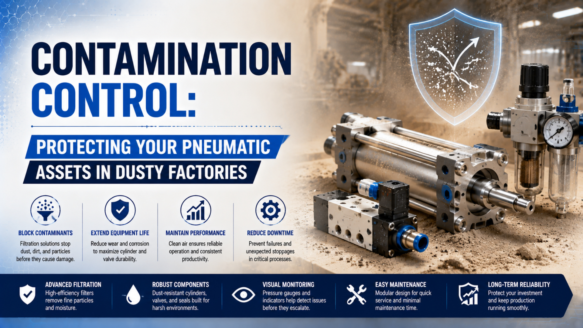
Contamination control in a dusty factory requires three separate actions: keep process dust away from moving interfaces, deliver compressed air at the purity required by each component, and prevent dirt from entering during installation or maintenance. A finer filter alone can’t correct external dust on a piston rod, an open cylinder slot, or a dirty tube cut.
The practical method is to trace the route before buying hardware. Record where residue appears, compare supply-side and external evidence, check the component manual, then verify the corrective action at the point of use. This approach avoids two expensive mistakes: changing cylinders without controlling the dust source and over-treating all plant air for one sensitive application.
Key Takeaways
- ISO 8573-1 separates particles, water, and oil into three purity parameters.
- External dust and supply-air contamination require different controls.
- Rodless construction alone doesn’t prove contamination resistance.
- Filter and seal maintenance limits must come from the installed model.
Where Does Contamination Enter a Pneumatic System?
ISO 8573-1 classifies compressed-air purity with three independent contaminant groups: particles, water, and oil (ISO, 2010). That gives a useful starting boundary, but dusty-factory failures usually involve three entry routes: dirty supply air, external material crossing a moving interface, and contamination introduced during installation or service.
Supply-side contamination is unwanted material transported through the pneumatic circuit. It can include intake dust, pipe scale, corrosion products, desiccant debris, liquid water, water aerosol, oil aerosol, oil vapor, hose fragments, or excess thread sealant. The material may originate upstream of the compressor room, inside the distribution network, or during branch-line work.
External contamination is material that reaches a moving or exposed interface from the machine environment. Typical paths include a piston rod and wiper, guide rail, carriage slot, sealing band, bearing, sensor groove, manual adjustment feature, or unprotected exhaust opening. Sawdust, grinding fines, cement powder, flour, fibers, paint residue, and coolant mist don’t behave alike. Particle hardness, shape, moisture, chemistry, and adhesion all matter.
Service-introduced contamination is debris admitted while ports, tubes, valves, filters, or cylinders are open. A freshly cut tube can carry chips. An uncapped hose can collect floor dust. Excess sealant can break loose downstream. Cleaning a component on a dirty bench may add the very debris the repair is meant to remove.
| Evidence location | More likely route | What to inspect next |
|---|---|---|
| Dust ring outside a rod wiper | External ingress | Rod finish, wiper, nearby dust plume, orientation |
| Similar residue in several devices on one branch | Supply-side transport | Point-of-use filter, pipe, dryer, branch samples |
| Debris appears after piping or seal work | Service introduction | Tube cutting, caps, tools, sealant, assembly area |
| Water in bowls and low points | Condensation or failed drainage | Pressure dew point, drain operation, pipe temperature |
| Sticky film in valve and actuator | Oil, process vapor, lubricant, or seal residue | Material compatibility and upstream/downstream samples |
The first stain isn’t always the source. A scored bore shows that hard material moved through a loaded contact, but it doesn’t establish whether the material came through the air supply, crossed the rod wiper, or formed as wear debris. Preserve the residue before cleaning and use the particle-origin investigation method when attribution matters.
In our experience, residue location is the quickest way to decide which boundary to sample first. Material concentrated outside a wiper points toward the machine environment, while a similar deposit across several devices on one branch makes the supply path a stronger initial hypothesis. It is a triage rule, not proof of origin.
Control the Dust Source Before Protecting the Actuator
OSHA describes combustible-dust explosions with five necessary elements: fuel, ignition, confinement, oxygen, and dispersion (OSHA Technical Manual, accessed 2026). Controlling the room process comes before choosing a cylinder because local extraction, enclosure, and safe housekeeping reduce both machinery exposure and the chance of turning settled material into an airborne hazard.
Start at the operation that generates contamination. Capture dust near a saw, grinder, transfer point, mixer, or filling station before it spreads across the machine. Repair leaking ducts and damaged guards. Check whether a process change has shifted the plume toward a cylinder or valve island. A cleaner component won’t stay clean when the source continues to discharge onto it.
Housekeeping must match the hazard assessment. Dust-rated vacuum equipment, suitable wet methods, and local extraction are usually better starting points than blowing settled material into the air. OSHA’s general-industry rule limits compressed air used for cleaning to less than 30 psi and also requires effective chip guarding and personal protective equipment (29 CFR 1910.242(b)). Combustible-dust areas may require stricter site procedures and ignition-source controls.
What if a blow gun is already part of the maintenance routine? Don’t treat the 30 psi limit as automatic permission. Review the dust hazard, local law, equipment classification, nozzle, guarding, nearby personnel, ignition sources, and approved cleaning procedure. Never use compressed air to clean clothing or a person’s body.
Machine layout can reduce exposure without changing the actuator:
- Move the cylinder out of the direct dust or spray trajectory.
- Put a guard between the process and the moving interface.
- Orient grooves, slots, and ledges so material doesn’t collect in them.
- Shield sensors, connectors, exhausts, and manual controls.
- Leave enough access for inspection without removing protection during production.
- Prevent covers from trapping water, heat, or abrasive material against the component.
The woodworking contamination case study illustrates why external dust, compressed-air quality, and maintenance practices should be investigated as separate branches. Correcting only one branch can leave the repeat-failure path untouched.
Which Cylinder and Actuator Features Matter in Dusty Areas?
SMC reports up to six times greater durability for a specified dust-resistant cylinder option tested with 20 to 100 µm powders, using a heavy-duty scraper and lubrication-retaining feature (SMC, accessed 2026). The claim is product- and condition-specific. It does not establish that every rodless cylinder outlasts every rod cylinder in dust.
Choose protection from the actual exposure and construction:
| Design option | Useful when | Check before selection |
|---|---|---|
| Heavy-duty rod scraper | Dry, abrasive particles collect on an exposed rod | Qualified particle range, rod coating, scraper material, replacement access |
| Rod boot or bellows | The rod needs a physical barrier from splash or debris | Stroke, speed, buckling, trapped moisture, fold cleaning, material compatibility |
| Guard or enclosure | The process plume can be intercepted outside the actuator | Heat, access, dust accumulation, cleaning method, hazardous-area requirements |
| Magnetic-coupled rodless cylinder | A closed tube avoids a longitudinal mechanical slot | Holding force, speed, moment, external slider path, magnetic debris |
| Mechanically coupled rodless cylinder | Long stroke and compact length are needed | Sealing-band exposure, carriage seals, guide protection, cleaning access |
| Guided cylinder or external guide | Side load and moment must be carried separately | Guide wipers, rail covers, lubrication, combined-load limits |
A conventional rod cylinder isn’t automatically the wrong choice. A model with a qualified heavy-duty scraper, suitable rod surface, compatible seals, correct mounting, and a process guard can be the most serviceable option. SMC’s dust-resistant products are a useful example precisely because the supplier defines the particle range and hardware rather than relying on a generic “dust-proof” label.
Rodless designs also need qualification. SMC’s CY-series magnetic-cylinder manual warns against direct exposure to dust, coolant, oil droplets, and foreign matter, and recommends a protective cover in dusty locations (SMC CY-series manual, accessed 2026). The closed pressure tube removes an exposed rod, but the external slider and guide environment still matter.
Count contamination interfaces, not product categories. A rod cylinder may expose one rod and wiper. A mechanically coupled rodless actuator may expose a long sealing band and carriage path. A magnetic-coupled unit avoids the slot but can attract ferrous debris near its slider. The relevant question is where material can collect, cross a seal, or damage a guide in the selected model.
From our work reviewing dusty pneumatic applications, protection that can’t be inspected safely is difficult to sustain. A guard may stop the process plume yet hide a damaged boot, packed sealing band, or dry guide. Selection should include a safe inspection path, not only an ingress barrier.
Ask the supplier for:
- the exact dust, liquid, or chemical exposure permitted
- scraper, wiper, boot, sealing-band, and guide materials
- validation conditions and excluded contaminants
- rod, tube, or rail surface treatment
- ambient temperature and pressure limits
- cleaning-agent and lubricant compatibility
- allowable speed, side load, moment, and duty cycle
- inspection and replacement instructions for protective parts
If a bore is already scored, don’t assume contamination is the only cause. Misalignment, side load, a damaged bearing, poor lubrication, or a manufacturing defect can create similar marks. Use the barrel-scoring failure guide to keep competing mechanisms in the investigation.
How Should Compressed Air Be Treated at the Point of Use?
CAGI groups the principal compressed-air contaminants into three categories, particles, water, and oil, and recommends treatment stages that match each physical form (CAGI Compressed Air Purity Guide, 2026). A point-of-use filter can protect an actuator from downstream pipe debris, but it cannot replace bulk-liquid separation or lower pressure dew point.
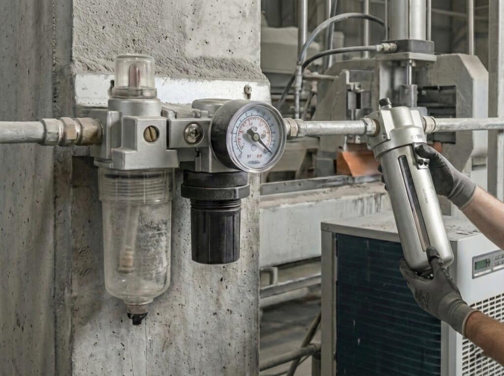
Point-of-use treatment should be selected from the component’s air requirement, peak flow, allowed pressure drop, condensate load, and service access.
Build the treatment train by job:
| Treatment stage | Primary job | It does not replace |
|---|---|---|
| Aftercooler | Reduces air temperature so vapor can condense | Separator, drain, dryer, or filter |
| Moisture separator and drain | Removes bulk entrained liquid | Water-vapor control |
| Particulate filter | Captures rated solid particles | Dryer or oil-vapor adsorber |
| Coalescing filter | Collects fine liquid water and oil aerosols | Dryer or complete oil-vapor removal |
| Dryer | Lowers water-vapor content and pressure dew point | Particle or oil control unless integrated |
| Adsorber | Reduces specified vapors after suitable pretreatment | Bulk-liquid separation |
| Point-of-use filter/regulator | Controls local particles and pressure | Central condensate and dew-point management |
Specify the required air at a named location. ISO 8573-1 uses separate particle, water, and oil classes, so “5 µm filtered air” is not a complete air-quality specification. Record the target class, sampling point, peak flow, minimum ambient temperature, inlet pressure, lubricant policy, and the component manufacturer’s requirements.
Fine filtration creates resistance. Size the filter from the supplier’s flow and pressure-drop data at the actual inlet pressure and peak demand. A small fine element can protect well at low flow yet starve a cylinder during simultaneous motion. When higher purity is needed, staged filtration keeps coarse material from loading the finest element too quickly.
Water needs separate attention. CAGI notes that a separator removes bulk liquid but doesn’t reduce pressure dew point; a dryer is needed when remaining vapor could condense downstream. If the branch or machine can fall below the dryer’s delivered pressure dew point, condensate may form close to the actuator even when the compressor room looks dry. The pressure-dew-point guide explains this temperature boundary.
For valves and small pilot passages, consult the exact manual. The site’s pneumatic valve contamination guide covers ISO class selection, sampling location, and treatment sequencing in more detail. For aerosol control, use the coalescing-filter guide without assuming that coalescing media also removes water vapor.
Build Maintenance Around Condition, Not a Generic Calendar
Parker specifies a 10 psig replacement differential for one P3A filter-regulator, while SMC lists 0.1 MPa or a time limit for selected AFF and AM-series elements (Parker; SMC). Those different thresholds show why a universal 5 psi rule is unreliable. Maintenance limits must come from the installed model’s documentation.
Create an asset record before choosing intervals. Include component model, serial or machine location, air-quality requirement, filter element, drain type, dryer branch, scraper or boot option, approved lubricant, cleaning restriction, and manufacturer replacement criteria. A calendar without that baseline turns maintenance into guesswork.
Use condition signals alongside stated time limits:
| Signal | Possible meaning | Confirm before acting |
|---|---|---|
| Rising filter differential pressure | Element loading or excessive peak flow | Compare at the same flow and inlet pressure |
| Water in the downstream line | Drain, separator, or dew-point problem | Check drain operation, dew point, and local temperature |
| Longer cycle time | Restriction, friction, pressure loss, or control issue | Record pressure and timing at consistent load |
| Rising air use | Leakage, seal wear, valve leakage, or process change | Isolate branches and repeat under the same state |
| Dust outside a wiper or band | External exposure or ineffective protection | Inspect plume, guard, interface, and cleaning method |
| New scoring or metallic debris | Abrasion, misalignment, bearing wear, or burr | Preserve debris and inspect geometry before attribution |
Inspect automatic drains by function, not by appearance. A failed-closed drain carries liquid downstream. A failed-open drain wastes air. Check bowls for chemical compatibility, cracks, clouding, and safe isolation before service. Depressurize the unit according to the equipment procedure; a clear bowl still contains stored pneumatic energy.
Protective hardware also needs a defined check. Look for scraper wear, cuts in a boot, trapped material in bellows folds, lifted sealing bands, damaged carriage wipers, dry guides, loose guards, blocked exhausts, and sensor-cable abrasion. Replace parts at the model’s limit, not because another cylinder used the same calendar.
Trend values under repeatable conditions. Differential pressure recorded at random flow rates, or cycle time measured with changing loads, can produce false maintenance alarms. A useful record states machine mode, inlet pressure, flow state, load, temperature, and sampling point so today’s result can be compared with the baseline.
We found that maintenance records become useful only when the measurement context is repeatable. A red differential indicator is actionable because it belongs to a defined product and flow condition. A handwritten “pressure looks high” note isn’t. Record the trigger, operating state, action, and result together.
How Do You Verify That Contamination Controls Work?
ISO 8573-4 defines two main particle results, size and number concentration, and requires attention to measurement limits and uncertainty (ISO, 2019). Verification should therefore compare named sampling points and operating states. A clean compressor-room sample doesn’t prove clean air at the actuator, and a damaged seal alone doesn’t identify the contamination source.
Set acceptance criteria before the change. Depending on the failure mode, useful criteria may include:
- particle, water, and oil classes at a named point
- pressure dew point at the operating pressure
- clean and loaded filter differential pressure
- downstream drain or residue condition
- cylinder cycle time at a defined load and pressure
- external dust accumulation at the rod, band, guide, or guard
- leakage trend after stabilization
- inspection interval with no new scoring, sticking, or seal damage
Sample upstream and downstream of a suspected boundary. A central-treatment outlet, remote header, point-of-use inlet, valve outlet, and failed component answer different questions. Keep the sampling tube clean, purge it as required by the measurement method, and record pressure, temperature, flow, operating state, and location.
Don’t mix every residue into one container. Photograph the component before cleaning. Keep particles from the rod end, cap end, ports, wiper, guide, filter bowl, nearby process, and known component materials separate. Composition, shape, distribution, location, and timing should support the same route before a source is assigned.
A trial installation needs a monitoring period tied to exposure, not a dramatic savings claim. Record the number of cycles or production hours, contaminant condition, inspections, interventions, and comparable baseline. If the trial succeeds, the result supports that model and duty. It doesn’t prove that the same design will survive cement dust, wet food powder, metal grinding fines, and paint residue equally well.
A Layered Contamination-Control Checklist
An effective contamination plan covers three barriers: control the process dust, condition the compressed air, and protect the component interface. ISO 4414 also treats maintenance and cleaning as system-design considerations, not afterthoughts (ISO, 2010). Use the checklist below as a commissioning record, then replace generic intervals with model-specific limits and measured condition.
Before selecting equipment
- Identify the contaminant, source, hardness, size range, moisture, chemistry, and combustible-dust status.
- Separate external ingress, supply-air transport, and maintenance-introduced debris.
- Record stroke, speed, load, moments, duty cycle, orientation, and cleaning method.
- Obtain air-quality, environmental, material, and protective-option limits from the exact component manual.
- Confirm that a guard, scraper, boot, or rodless construction won’t create a new load, heat, access, or accumulation problem.
During installation
- Cap open ports and tubes until connection.
- Cut tubing cleanly, deburr where the system requires it, and remove chips.
- Control thread sealant so it can’t enter the flow path.
- Install filters, drains, and dryers in the required orientation and sequence.
- Keep guards and covers accessible for inspection.
- Lock out and exhaust stored energy before opening the circuit.
During commissioning
- Record clean filter differential pressure at a defined flow state.
- Verify pressure, flow, dew point, and air purity where required.
- Check full-stroke motion, leakage, cushioning, sensor operation, and guide behavior.
- Photograph protected interfaces and set an inspection baseline.
- Confirm that the cleaning procedure doesn’t disperse hazardous dust or expose personnel.
During operation
- Compare trends under the same machine state.
- Inspect residue location before wiping it away.
- Test drains and alarms.
- Investigate a recurring failure before installing another identical replacement.
- Update the control plan when the process material, extraction, cleaning chemistry, or machine layout changes.
The safest decision isn’t always the finest filter or the most enclosed actuator. It is the combination that controls the identified route, fits the motion duty, can be maintained safely, and produces measurable evidence at the point of use.
Pneumatic Contamination Control FAQs
ISO 8573-1 uses three independent purity parameters, while SMC’s CY magnetic-cylinder manual specifies a 5 µm upstream filter for that particular product family (ISO; SMC, accessed 2026). The FAQ answers below keep that distinction: broad system rules define the method, but product manuals define the final selection and maintenance limits.
Is 5 µm filtration always required in a dusty factory?
No. A 5 µm filter is a published requirement for some pneumatic products, not a universal plant rule. Start with the component manual and the required ISO 8573-1 particle, water, and oil classes. Then size the selected stages for peak flow, allowed pressure drop, inlet condition, and the sampling point where purity must be achieved.
Are rodless cylinders always better in dusty environments?
No. A magnetic-coupled cylinder removes the exposed piston rod, while a mechanically coupled design introduces a longitudinal sealing band and carriage interface. Both still have external parts that need protection. Compare the exact model’s dust limitations, guide system, coupling, sealing arrangement, load capacity, cleaning access, and supplier test conditions before selecting it.
Should protective boots be fitted to every rod cylinder?
Only when the boot material, stroke, speed, mounting space, cleaning method, and contaminant suit the application. A boot can shield the rod, but its folds may collect particles or moisture and it can hide damage. Heavy-duty scrapers, guards, relocation, or a different actuator construction may provide a more serviceable control.
Can compressed air be used to blow dust off pneumatic equipment?
Only under an approved procedure that addresses the dust hazard and applicable law. OSHA’s general-industry rule requires less than 30 psi, effective chip guarding, and personal protective equipment. Combustible-dust areas also require controls against dispersion and ignition. Dust-rated vacuuming, local extraction, or suitable wet cleaning may be safer.
How can maintenance teams tell whether contamination controls are working?
Define a baseline and repeat the same observations at named locations and operating states. Track air-purity results, pressure dew point, filter differential pressure, drain function, leakage, cycle time, and residue location. Preserve failed-part evidence. A reduction in repeat failures is useful only when exposure, operating hours, interventions, and comparison conditions are documented.
Sources and technical references
- ISO 8573-1:2010, compressed-air contaminants and purity classes
- ISO 8573-4:2019, particle-content measurement
- ISO 4414:2010, pneumatic-system safety requirements
- OSHA Technical Manual, combustible dust
- OSHA 29 CFR 1910.242, compressed air used for cleaning
- CAGI Compressed Air Purity Guide
- SMC dust-resistant cylinder options
- SMC CY-series magnetic cylinder operating manual
- Parker P3A filter-regulator service instructions
- SMC AFF and AM-series filter maintenance guidance