

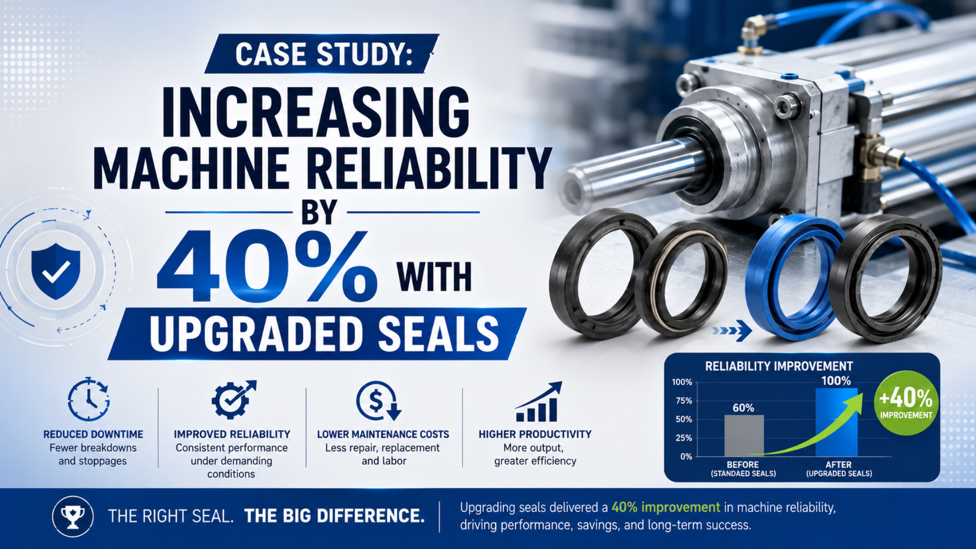
A seal upgrade can improve machine reliability, but a 40% gain is credible only when the failure definition, operating exposure, asset population, comparison periods, and changed hardware are documented. The source material supplied for this case does not include those underlying records. Its percentage therefore cannot be independently confirmed.
That limitation doesn’t make seal improvement unimportant. It changes the question. Instead of assuming a premium material fixes every leak, reliability teams should establish whether the seal was the initiating failure, select a model-specific replacement, and compare normalized failure rates before and after the controlled change.
Key Takeaways
- Treat 40% as a result to verify, not a benefit promised by a material name.
- Normalize failures by cycles, travel, or operating hours.
- Separate seal damage from side load, contamination, surface, and assembly causes.
- Keep every other operating condition visible during the comparison.
- Approve the change only after leakage, motion, safety, and cost checks pass.
Can Upgraded Seals Really Increase Machine Reliability by 40%?
A 40% improvement is mathematically possible, but ISO 19973-1 requires reliability results to be tied to stated test conditions, failure criteria, calculation, reporting, and statistical evaluation (ISO 19973-1, 2015). A percentage without those records is a hypothesis, not a transferable machine-reliability result.
Start by defining machine reliability. Possible measures include:
- seal-related failures per million cycles;
- seal-related failures per 1,000 operating hours;
- mean operating time between defined failures;
- unplanned downtime hours caused by the defined failure;
- the share of scheduled cycles completed without a seal-related interruption.
These measures are related, but they aren’t interchangeable. A 40% reduction in failure rate does not automatically mean 40% less downtime. Repair duration, spare-part availability, fault detection, production scheduling, and secondary damage can change downtime independently.
The same warning applies to MTBF. Increasing MTBF by 40%, reducing failures by 40%, and reducing annual cost by 40% are three different claims. The numerator, denominator, observation period, and asset boundary must appear beside each result.
From our analysis of ISO 19973-1 and ISO 19973-3, a good case study begins with a metric dictionary, not the outcome. Define “failure,” “cycle,” “operating hour,” “downtime,” and “seal-related” before collecting the baseline. If those definitions change after the upgrade, the comparison has already failed.
For published endurance claims, the high-cycle pneumatic cylinder evidence guide explains why a cycle total needs a failure threshold, population, and declared operating conditions.
Is the Seal the Root Cause or the Part That Finally Leaked?
ISO 8573-1 classifies compressed-air contaminants into 3 groups: particles, water, and oil (ISO 8573-1, 2010). Any of them can affect a dynamic sealing interface, yet air quality is only one branch. Alignment, guide condition, surfaces, temperature, chemicals, lubrication, pressure, and assembly also require evidence.
A leaking or torn seal is a failed component. It is not automatically the initiating cause. For example, a worn guide bushing can let the rod run off-axis, which concentrates contact on one sector of the rod seal. Replacing only the seal may reset the symptom while preserving the load path that damaged it.
Use the physical evidence to choose the next measurement:
| Evidence found during controlled teardown | Plausible initiating conditions | Confirmation needed before changing material |
|---|---|---|
| Wear concentrated on one side of the lip | Misalignment, side load, bent rod, guide wear | Alignment under load, rod runout, guide clearance, load direction |
| Axial scratches or embedded particles | Damaged wiper, contaminated assembly, rod damage, airborne debris | Rod surface, wiper, captured particles, point-of-use air record |
| Clean cut or rolled lip after maintenance | Sharp assembly edge, wrong tool, incorrect orientation or part | Chamfer and groove inspection, service-kit identity, assembly record |
| Hard, cracked, or low-elasticity seal | Excess temperature, aging, unsuitable compound, ozone | Measured temperature history and exact compound rating |
| Swollen, sticky, or softened material | Cleaner, lubricant, process fluid, or grease incompatibility | Chemical identity, concentration, exposure time, supplier compatibility data |
| Extruded or nibbled edge | Excess clearance, pressure transient, damaged hardware, unsuitable profile | Dynamic pressure, hardware dimensions, model-specific allowable limits |
Preserve the seal’s installed orientation, photograph the rod and guide before cleaning, and keep representative debris when the maintenance procedure permits. A loose seal on a clean bench has lost much of its diagnostic context.
The piston rod seal leak fault tree separates rod-end leakage from piston bypass, valve leakage, and connection leaks. The particle-origin analysis provides a deeper workflow when debris is present.
What Records Make a Seal-Upgrade Study Defensible?
ISO 19973-3 reports pneumatic-cylinder life in 2 exposure units, cycles or kilometres, for its stated rod-cylinder test scope (ISO 19973-3, 2015). A field study may use operating hours instead, but it still needs a consistent exposure measure and five linked records that make the before-and-after comparison auditable.
1. Failure boundary
State what counts as a seal-related failure. External leakage above an agreed test limit, internal bypass beyond an acceptance value, incomplete stroke, cycle-time drift, or visible seal damage may qualify. A planned inspection replacement should not silently become an unplanned failure.
2. Baseline exposure
Record each asset ID, cylinder part number, bore, stroke, seal option, mounting, load, speed, cycle count or running hours, point-of-use pressure, temperature, air condition, maintenance, and every qualifying failure. Use actual controller counts when available. Calendar months alone conceal idle time and production-rate changes.
3. Controlled change
Identify the exact replacement seal or service kit, compound, profile, revision, supplier, batch, installation procedure, lubricant, and changed hardware. Inspect the rod, bore, guide, groove, wiper, and bearing. If a damaged guide and a new seal are installed together, record both changes.
4. Comparison exposure
Apply the same data fields and failure criteria after the change. Track recipe, product, speed, pressure, load, cleaning agent, ambient condition, air treatment, maintenance practice, operator response, and production schedule. A quieter operating period can create an apparent improvement even when the seal has no effect.
5. Acceptance decision
Set the required improvement, minimum observation exposure, leakage limit, motion criteria, inspection interval, and response to an early failure before the trial starts. Use a staged population when a machine-wide change would create unacceptable production or safety risk.
How Should the 40% Reliability Improvement Be Calculated?
If a baseline records 12 qualifying failures per million cycles and the comparison records 7.2 per million, the normalized failure-rate reduction is 40%. This is an illustrative calculation, not plant data. ISO 19973-1 requires the calculation and statistical treatment to be reported with the test conditions (ISO 19973-1, 2015).
First calculate the failure rate for each period:
Here, is the failure rate, is the number of failures meeting the fixed definition, and is the operating exposure. Use one exposure unit throughout, such as machine cycles, kilometres of seal travel, or operating hours.
Then calculate the relative failure-rate reduction:
Here, is the relative improvement. The expression assumes the two rates use the same failure boundary and comparable exposure. If is zero, the percentage is undefined and another evaluation method is required.
For the illustrative rates:
Do not compare raw failure counts when exposure changed. Eight failures during two million cycles is a lower rate than six failures during one million cycles, even though the raw count is higher.
MTBF can support the analysis for repairable assets:
Here, is the combined operating exposure of the observed population and is the qualifying failure count. State whether planned downtime, idle time, censored assets, and non-seal failures are included. Never average individual MTBF values without checking that the weighting and exposure basis are valid.
The most useful denominator is the one closest to seal work. Operating hours are easy to obtain, but accumulated travel reflects sliding exposure more directly when stroke and cycle rate vary. Keep both when the controller can provide cycle counts and the stroke is known.
When Should You Choose the Seal Material?
ASTM D395 contains 3 compression-set methods for rubber under constant deflection or force, mainly in static applications (ASTM D395-18(2025), 2025). That test can compare one material property, but it does not predict dynamic pneumatic-seal life by itself. Product-level geometry, pressure, speed, media, surfaces, and lubrication still govern selection.
Avoid choosing a material from a generic “good, better, best” chart. NBR, polyurethane, HNBR, FKM, PTFE-based compounds, and other formulations include many grades. Two compounds with the same polymer family name can have different hardness, low-temperature behavior, abrasion resistance, compression set, additives, and chemical compatibility.
For example, Trelleborg publishes one defined pneumatic piston-seal range for 4 to 250 mm diameters, pressure up to 1.6 MPa, temperature from -40°C to +85°C, and speed up to 1 m/s (Trelleborg Sealing Solutions Product Range, accessed 2026). Those limits belong to the specified product range. They are not universal polyurethane limits.
Use this selection sequence:
- Confirm the initiating failure mechanism and damaged interfaces.
- Identify the exact cylinder, groove, rod or bore condition, seal profile, and service-kit specification.
- Define minimum, normal, and maximum temperature at the seal, not only room temperature.
- List compressed-air lubricant, assembly grease, cleaners, process fluids, washdown chemicals, ozone, and external contaminants.
- Record working pressure, transients, speed, stroke, cycle rate, dwell, side load, and expected travel.
- Obtain written supplier compatibility and performance limits for the exact compound and profile.
- Trial the complete configuration under representative conditions.
ISO 3601-2 specifies housing dimensions for O-rings in general hydraulic and pneumatic applications, but it also recognizes that special applications may require agreement between user and manufacturer (ISO 3601-2, 2025). Do not assume that dynamic lip seals or complete service kits interchange across brands because the nominal bore matches.
Food-contact language also needs product-level evidence. The FDA explains that regulatory status depends on each substance, intended use, and applicable authorization or notification (FDA, accessed 2026). “FDA polyurethane” on its own does not establish that a finished seal is suitable for a particular food process.
For material details, use the temperature and cylinder-seal selection guide and the industrial cylinder seal types overview. The present study should record the selected product, not repeat generic material rankings.
What Other Changes Can Distort the Result?
Changing 1 seal while also reducing speed, adding filtration, correcting alignment, and replacing guides prevents a clean seal-only attribution. The machine may still become more reliable, but ISO 19973-1’s reporting principle requires the relevant conditions to remain visible (ISO 19973-1, 2015). Record every simultaneous intervention and treat the result as a package change.
Common confounders include:
- a product or recipe change that lowers cycles, speed, load, or impact;
- new air filtration, drying, lubrication, or pressure settings;
- corrected mounting, external guidance, rod alignment, or hose forces;
- replacement of rods, bores, wear rings, bushings, wipers, or valves;
- revised cleaning chemicals or washdown practice;
- planned maintenance introduced during the comparison period;
- seasonal changes in ambient or process temperature;
- improved fault detection that changes how failures and downtime are recorded;
- operator or shift changes;
- survival bias from excluding the worst assets.
A parallel control group can help when enough comparable assets exist. If matched machines run the same product and duty, upgrade one group first and retain the existing approved configuration in the other for a defined exposure. This does not remove every confounder, but it makes plant-wide changes easier to detect.
Small samples require restraint. One avoided failure can produce an impressive percentage when the baseline count is low. Report the counts and exposure beside the rate, extend the observation period, and use a reliability specialist when confidence intervals, censored data, or safety-critical acceptance decisions matter.
Safe Implementation and Acceptance Checks
ISO 4414 provides 1 system-level framework for pneumatic equipment safety, reliable operation, installation, use, and maintenance (ISO 4414, 2010). A seal trial must therefore control stored pneumatic and mechanical energy, unintended motion, suspended loads, pressure restoration, and machine-specific hazards before any cylinder is opened or returned to service.
Use the cylinder manufacturer’s service instructions and the site’s isolation procedure. At minimum:
- Bring the machine to a defined safe state and isolate all relevant energy sources.
- Restrain gravity, springs, tooling, accumulators, and other stored mechanical energy.
- Confirm depressurization using the approved procedure. Do not rely on a gauge alone.
- Remove the cylinder without forcing the rod, ports, tube, or mounting.
- Clean externally before disassembly and prevent debris from entering the component.
- Inspect the rod, bore, groove, bearing or guide, wiper, piston, end caps, and fasteners against service limits.
- Use the specified service parts, tools, orientation, lubricant, tightening sequence, and torque.
- Restore pressure in a controlled manner and check external leakage, internal bypass, full stroke, speed, cushioning, sensors, alignment, and load behavior.
- Record the installed configuration and establish the next inspection point.
A seal that stops visible leakage but causes excessive friction, breakaway pressure, stick-slip, timing drift, or heat has not passed the machine acceptance test. The trial criteria should cover function as well as leakage.
The pneumatic actuator maintenance checklist can supply the recurring inspection fields. If wear is concentrated on one side, review the rod-bearing and repeat seal-failure guide before approving another kit.
Turning Reliability Results Into a Business Case
A business case should separate at least 4 cost groups: lost production, maintenance labour, replacement parts, and consequential costs. ISO 19973-1 requires reliability calculations and conditions to be reported; the same traceability should govern financial inputs (ISO 19973-1, 2015). Do not convert an unverified downtime rate into a precise ROI.
Calculate avoided cost from validated differences:
Here, is the avoided cost over the stated period, is the reduction in production downtime, is the approved production cost per downtime hour, is the reduction in maintenance labour time, is the loaded labour rate, is the verified parts-cost change, and is the verified consequential-cost change.
Keep avoided cost separate from recovered production value. A machine may regain available hours without having customer demand, materials, labour, or downstream capacity to convert every hour into revenue. Finance and operations should approve the cost-per-hour method and decide whether margin, contribution, revenue, or another measure belongs in the model.
Compare the avoided cost with all implementation costs:
- seals, kits, cylinders, guides, rods, valves, and other changed hardware;
- engineering review and compatibility testing;
- planned installation labour and production window;
- validation, inspection, documentation, and training;
- additional maintenance or air-treatment requirements;
- obsolete spares and inventory changes.
We analyzed the reporting chain as two separate decisions. The reliability conclusion states what changed per unit of operating exposure. The financial conclusion states what that verified change was worth under an approved cost model. Combining them too early turns assumptions into false precision.
Pneumatic Seal Upgrade FAQs
ISO 19973-3 uses cycles or kilometres as 2 valid cylinder-life exposure measures in its stated scope (ISO 19973-3, 2015). The practical FAQ answers below apply the same principle: define the condition, record the denominator, and verify the exact seal and cylinder rather than relying on a material label.
Does a premium seal automatically increase cylinder life?
No. A higher-cost seal can still fail early if the initiating problem is misalignment, a damaged rod, guide wear, contamination, chemical incompatibility, an incorrect profile, or installation damage. Approve the change only after the failure mechanism and exact product limits match the application, then verify performance over representative operating exposure.
What should count as a seal-related failure?
Define it before the baseline. Examples include external leakage above an agreed limit, internal bypass beyond a test threshold, incomplete motion caused by the sealing interface, or confirmed seal damage requiring unplanned intervention. Record exclusions separately, including planned replacements, valve leaks, fitting leaks, and failures initiated by unrelated machine hardware.
Should reliability be measured in cycles or operating hours?
Use the exposure that best represents the duty, and keep it consistent. Cycles suit repetitive machines; accumulated travel adds insight when stroke varies; operating hours may fit irregular motion. When possible, retain both controller cycle counts and hours. Calendar months alone are weak because production rate and idle time can change.
Can seals be interchanged between cylinder brands?
Not from bore size or polymer name alone. Confirm the cylinder part number, groove, profile, dimensions, tolerances, rod or bore surface, pressure direction, lubricant, and service-kit documentation. ISO 3601-2 covers O-ring housings, not universal interchangeability for every dynamic lip seal or proprietary pneumatic-cylinder sealing system.
How long should a seal-upgrade trial run?
Long enough to exceed the relevant baseline exposure and capture the dominant operating conditions. A fixed number of weeks is insufficient when cycle rate, product mix, temperature, or cleaning varies. Predefine a minimum cycle, travel, or operating-hour threshold, include seasonal or recipe extremes where relevant, and state the remaining uncertainty.
Sources and technical references
- ISO 19973-1:2015, Pneumatic fluid power component reliability assessment, general procedures
- ISO 19973-3:2015, Pneumatic fluid power component reliability assessment, cylinders with piston rods
- ISO 4414:2010, General rules and safety requirements for pneumatic systems
- ISO 8573-1:2010, Compressed-air contaminant and purity classes
- ISO 3601-2:2025, O-ring housing dimensions
- ASTM D395-18(2025), Rubber property, compression set
- FDA, Determining the regulatory status of food-contact material components
- Trelleborg Sealing Solutions product range