

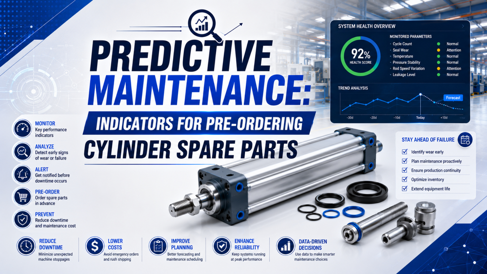
Predictive maintenance does not tell a maintenance planner the exact day a pneumatic cylinder will fail. It provides enough evidence to investigate a change, confirm the affected component, identify the correct spare, and place an order before a planned work window closes.
That distinction matters. A slow stroke can come from a worn piston seal, but it can also come from low supply pressure, a restricted valve, an incorrectly set flow control, damaged tubing, excessive load, or poor alignment. Ordering a seal kit from one trend alone can leave the real fault untouched.
Key Takeaways
- ISO 17359 provides a 29-page framework for condition-monitoring programs, but it does not prescribe universal cylinder alarm limits.
- Track 6 signal groups against a controlled healthy baseline.
- Confirm the fault before selecting a seal kit, sensor, rod assembly, or complete cylinder.
- Set the order date from replenishment time, work-window date, and risk buffer.
Predictive maintenance for cylinder spare parts is a controlled decision process that links condition evidence to diagnosis, part identification, procurement timing, and maintenance planning. Its output is not merely an alarm. The useful output is an approved action with a part number, quantity, required-on-site date, and evidence trail.
Predictive Maintenance Is a Decision Process, Not a Failure Timer
Build the program around repeatable decisions, not a countdown to failure. ISO 17359:2018 is a 29-page standard describing general procedures for condition-monitoring programs across machines, while NIST found only 42 eligible evaluations among 465 relevant studies in a systematic review. Neither source supports a universal cylinder failure timer (ISO 17359; NIST, retrieved 2026-07-26).
The practical sequence is:
- establish the normal condition for one controlled operating state;
- detect a repeatable departure from that condition;
- verify the measurement and reproduce the symptom;
- isolate the cylinder from upstream, circuit, load, and alignment causes;
- identify the repair level and exact compatible part;
- compare the required-on-site date with total replenishment time;
- place, defer, or cancel the order with a recorded reason.
This gate structure also separates condition-based work from ordinary preventive work. A time-based seal replacement can still be appropriate when the manufacturer specifies it or when the process risk demands it. Predictive evidence becomes valuable when it changes the timing, scope, or part choice.
The 2018 edition of ISO 4414 sets general rules and safety requirements for pneumatic systems and their components. Any inspection, isolation, pressure release, restart, or functional test must therefore follow the machine’s risk assessment, energy-control procedure, and authorized maintenance method (ISO 4414, confirmed 2023).
How Should a Healthy Baseline Be Established?
Record baseline data under defined operating conditions before interpreting a trend. ISO 13379-1:2025 contains 39 pages covering diagnostic concepts, operational inputs and outputs, and selection of an appropriate diagnostic approach. A single pressure or cycle-time value without its operating context is not a defensible health reference (ISO 13379-1, 2025).
Choose an operating state that the machine can repeat. For example, capture ten or more complete cycles after warm-up with the same product, payload, supply-pressure range, regulator setting, flow-control settings, motion sequence, and data sampling method. The sample count is a plant decision, not a universal standard threshold. Record enough cycles to see ordinary process variation.
The baseline record should include:
| Field | Why it belongs in the baseline |
|---|---|
| Asset and cylinder identity | Connects the trend to the correct machine position, model, bore, stroke, and revision |
| Load and orientation | Separates cylinder condition from a changed force or side-load case |
| Supply and port pressures | Shows whether the actuator received comparable pneumatic input |
| Extend and retract times | Reveals direction-specific changes and sequence effects |
| End-position confirmation | Distinguishes motion completion from a timer assumption |
| Air consumption per cycle | Adds a system-level leakage or demand signal when measured correctly |
| Temperature state | Prevents cold-start and stabilized operation from being mixed |
| Noise or ultrasound record | Gives a reference for newly developed leakage or mechanical contact |
| Maintenance state | Records lubrication, adjustments, replaced parts, and inspection findings |
Festo lists operating pressure, air consumption per cycle, and process cycle times as monitorable values in a compact-handling condition-monitoring library. These are useful signal categories, but their meaning still depends on application controls and baseline quality (Festo, retrieved 2026-07-26).
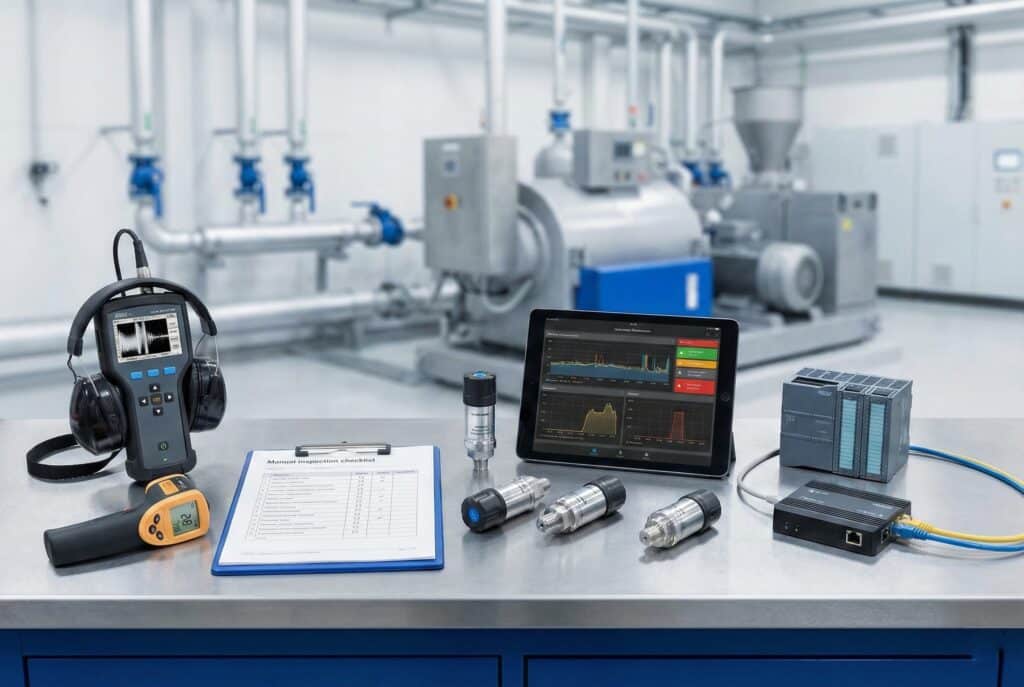
A condition-monitoring toolkit can combine measurements and inspection evidence. No single instrument proves which cylinder part should be ordered.
Use a normalized deviation when units or scales differ:
Here, is the relative change in a measured variable, is the current value, and is the approved reference under the same operating state. A positive result means the current value is higher; a negative result means it is lower. The formula does not create an alarm threshold. Establish warning and action limits from measurement capability, known-good variation, application consequence, and verified failure evidence.
A baseline should have a version, not just a date. If a valve, regulator, tube size, payload, flow setting, control sequence, or cylinder revision changes, the old reference may no longer describe the healthy machine. Retain it for history, then qualify a new baseline instead of quietly overwriting the original.
Which Cylinder Signals Deserve Investigation?
Investigate 6 signal groups together: pressure behavior, motion time, end position, air demand or leakage, temperature, and sound or vibration. NIST’s review covered 465 relevant condition-monitoring studies but accepted only 42 for detailed evaluation, highlighting why a visible trend is evidence to investigate rather than proof of a specific failure (NIST, 2025).
| Signal group | Useful observation | Plausible cylinder-related cause | Important competing causes |
|---|---|---|---|
| Pressure behavior | Chamber fill, pressure rise, pressure under motion, trapped-pressure decay | Piston-seal bypass, rod-seal leakage, damaged tube or band seal | Low supply, regulator droop, restricted valve, undersized fittings, leaking circuit |
| Motion time | Extend and retract duration at a controlled load | Rising seal friction, guide wear, cushion change, internal leakage | Flow-control adjustment, valve delay, changed payload, bent mechanism |
| End position | Repeatability and time to confirmed switch state | Cushion or mechanical wear, insufficient force, rod or guide damage | Sensor movement, control timing, hard stop, external alignment |
| Air demand or leakage | Consumption per comparable cycle, isolated leakage | Worn dynamic seal, damaged port, tube or barrel defect | Valve leakage, tubing damage, fitting leak, another branch load |
| Temperature | Stabilized housing, guide, seal, or bearing temperature | Friction, inadequate compatible lubrication, side loading | Ambient or process heat, hot supplied air, external heat source |
| Sound or vibration | Hiss, impact, scraping, changed frequency content | External leak, cushion impact, mechanical contact, looseness | Valve exhaust, machine structure, nearby rotating equipment |
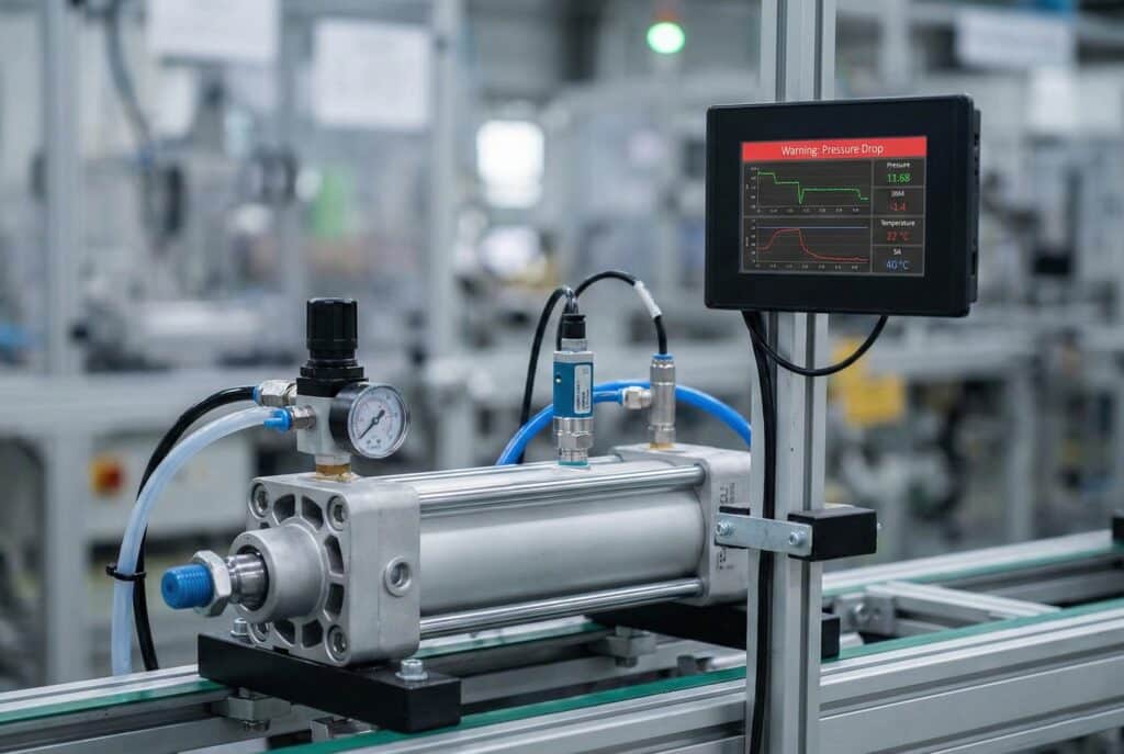
Pressure behavior is a diagnostic input, not a direct seal-wear verdict. Compare it with valve state, supply conditions, motion, load, and isolation-test results.
Trend extend and retract directions separately. A rod-side restriction, direction-specific valve problem, misaligned load, or cushion adjustment may affect only one movement. Combining both strokes into one average can hide that distinction.
Do not infer remaining life from a percentage change unless a validated model exists for that exact application. A 5% cycle-time change could be meaningful in one tightly controlled machine and ordinary product variation in another. Similarly, a warmer cylinder is not automatically failing. The measurement needs a consistent location, emissivity treatment for thermal imaging, stabilized operating state, and comparison with load and ambient conditions.
For a deeper thermal investigation, use the high-cycle cylinder seal heat analysis. If the symptom is a pressure change at the actuator, first review pressure-drop dynamics across ports and fittings before attributing it to an internal seal.
How Do You Confirm the Cylinder Is the Fault?
Use a four-part circuit check before condemning the cylinder. SMC’s troubleshooting guide separates the pneumatic path into filter and regulator, control valve, fittings or tubing or speed controller, and cylinder. Parker likewise lists low pressure, adjustment, load, contamination, seal, and rod-related causes for similar symptoms (SMC; Parker).
Start with a safe visual and document check:
- verify the machine state, product, recipe, load, and recent change history;
- confirm cylinder model, serial or asset identity, drawing revision, and ports;
- look for loose mounts, side load, damaged guides, impact marks, contamination, and hose movement;
- inspect the rod, barrel, band, wiper, fittings, and sensor mounting where applicable;
- confirm the regulator, valve command, flow controls, silencers, and exhaust path;
- validate the measuring instrument and its range, location, sample rate, and timestamp.
Then reproduce the symptom under the baseline state. If it disappears, record what differed before ordering anything. If it remains, divide the circuit into testable sections. Follow the machine manufacturer’s safe isolation method and never loosen a pressurized connection.
For suspected external leakage, locate the leak and prove whether it is at a fitting, tube, port, rod seal, barrel, band, valve, or adjacent component. For suspected internal bypass, isolate the cylinder only through an approved procedure and interpret the result with the valve configuration, load, piston position, cushioning, and trapped volume in mind. Parker’s troubleshooting guidance warns that drift can originate elsewhere in the system, so an opposite-port or isolation test needs a controlled setup.
For slow or erratic motion, check available pressure while the cylinder is moving, not only static regulator pressure. Inspect the valve, silencers, fittings, tubing, speed controls, load, alignment, guides, and cushion settings. The internal valve leakage failure-analysis guide helps prevent a leaking directional valve from being mistaken for piston-seal bypass.
In our experience, the most useful evidence package is rarely a dashboard screenshot alone. A short record containing the asset ID, exact operating state, extend and retract traces, valve command, supply pressure, port pressure, load, repeatability, photos, and isolation result gives maintenance and the parts supplier something they can actually verify.
Matching Evidence to the Correct Spare Part
Match the repair level to confirmed damage and the controlled bill of material. ISO 4414 is 38 pages of general pneumatic-system rules and safety requirements, not a parts-interchangeability catalog. A seal with the right diameter may still have the wrong profile, compound, hardness, lubricant compatibility, or installation geometry (ISO 4414, 2010).
Use this evidence-to-part map as a starting point:
| Confirmed finding | Candidate service item | What must be verified before ordering |
|---|---|---|
| External leak at rod seal with serviceable rod and gland | Manufacturer-specified seal or repair kit | Exact series, bore, rod size, revision, compound, wiper, lubricant, installation tools |
| Internal piston bypass with serviceable barrel and piston | Piston-seal or full seal kit | Bore, piston design, wear ring, cushion seals, material compatibility, repair instructions |
| Scored, bent, corroded, or dimensionally damaged rod | Rod assembly or complete cylinder | Rod material and coating, thread, length, piston attachment, gland and bearing condition |
| Excessive guide or carriage play | Guide bearing, wear strip, carriage kit, or guided unit | Load history, rail condition, adjustment method, matched components, alignment cause |
| Intermittent or failed position signal | Sensor, mounting hardware, cable, or connector | Output type, voltage, logic, connector, cable length, slot and magnetic compatibility |
| Barrel, tube, inner band, structural mount, or nonserviceable body damage | Major assembly or complete cylinder | Repair authorization, dimensional inspection, pressure boundary, test and acceptance scope |
Do not assume every cylinder is field-repairable. Some products require special fixtures, matched parts, factory assembly, controlled lubrication, or post-repair leakage and functional testing. The repair instruction, not the presence of a seal kit in a catalog, should decide whether the work is permitted on site.
Capture at least these procurement identifiers:
- machine, station, axis, and asset number;
- manufacturer and complete cylinder code;
- bore, stroke, rod or carriage configuration, and mounting;
- port thread, port orientation, cushion, and sensor arrangement;
- drawing, BOM, and product revision;
- seal compound or environment option;
- quantity installed, quantity affected, and quantity requested;
- approved alternative and deviation record, if any;
- photos of the nameplate, ports, mount, rod end, sensor, and damaged area;
- required inspection, certificate, test, preservation, and shelf-life information.
If repair scope is still uncertain, compare the complete evidence using the repair-versus-replace decision process. For rod-seal symptoms, the piston rod seal leakage guide shows why rod surface, alignment, contamination, gland condition, and pressure must be inspected before replacing the seal alone.
When Should the Order Be Placed?
Calculate backward from the planned work date through 5 time elements: internal approval, supplier lead time, receiving, validation, and an explicit buffer. ASCM warns that simple percentage or two-week safety-stock rules ignore demand and lead-time variability, so a fixed pre-order interval is not defensible for every cylinder (ASCM, 2025).
Use:
is the latest approved order date and is the planned maintenance date. The terms are durations for internal approval, supplier fulfillment, receiving or import, and incoming validation. is the agreed risk buffer. Use the same calendar basis for every duration and state whether weekends, shutdowns, and holidays count.
The supplier term should include more than fabrication:
- technical clarification and configuration confirmation;
- material and bought-out component availability;
- production, outside processing, and assembly;
- inspection, testing, and documents;
- packing, collection, transport, customs, and final delivery point;
- nonconformance or rework allowance where the risk analysis requires it.
The custom cylinder lead-time guide explains how to separate forecast, committed, shipped, delivered, and accepted dates. For a predictive order, add the condition-evidence date and planned work-order date so procurement can see why the part is needed and when it must be ready.
The latest order date is not automatically the purchase date. If diagnosis confidence is still low, maintenance can reserve supplier capacity, request a quotation, confirm configuration, or obtain approval without releasing a nonreturnable part. Split the process into reversible and irreversible commitments, then define who can cross each gate.
Escalate when the current date reaches the calculated order date, when supplier lead time changes, when the planned shutdown moves earlier, or when condition evidence changes the repair scope. A weekly review of those four events is more useful than a generic “order three weeks before failure” rule.
Criticality-Based Spare Stock Policy
Set stock policy from asset consequence and total replenishment time, then refine it with repairability, demand, commonality, and obsolescence. IBM’s MRO criticality framework poses 8 questions covering asset criticality, supplier, lead time, warehouse, BOM, usage, service level, and work-order priority, illustrating why condition severity alone cannot determine stock (IBM, retrieved 2026-07-26).
For each cylinder position, answer:
- Could failure create an unacceptable safety, environmental, or quality risk?
- How much production, downstream work, or customer delivery would be affected?
- Is the cylinder unique, or is an identical verified unit installed elsewhere?
- Can a kit restore it within the allowed downtime, and is that repair authorized?
- Is a complete replacement interchangeable in mounting, stroke, ports, force, sensors, cushioning, and environment?
- What is the observed supplier, transport, receiving, and validation time?
- Could the stored seal material, lubricant, coating, sensor, or design become obsolete?
- How will the spare be identified, preserved, inspected, rotated, and linked to the BOM?
A critical spare that cannot be found, has an obsolete sensor, contains aged seals, or no longer matches the machine drawing is not reliable protection. Give stored cylinders an asset relationship, preservation method, inspection interval, owner, and change-control rule. When the machine changes, review its spares at the same time.
NIST’s manufacturing-maintenance research associates predictive approaches with lower downtime, defect, and inventory-increase outcomes across broad manufacturing establishments, but it does not establish a cylinder-specific ROI. Its 2024 simulation paper also notes that application configuration and procedures materially affect condition-monitoring performance (NIST maintenance research; NIST simulation paper).
Cylinder Spare-Parts FAQs: What Should Maintenance Teams Ask?
Use the FAQs as a final 5-question control before releasing an order. ISO 17359 supplies a 29-page general condition-monitoring framework, while ISO 4414 supplies 38 pages of pneumatic-system safety and application rules. Neither replaces the cylinder drawing, manufacturer repair instruction, plant risk assessment, or verified BOM (ISO 17359; ISO 4414).
Can pressure drop prove that a piston seal is worn?
No. Pressure behavior can support the diagnosis, but low supply pressure, regulator droop, valve restriction or leakage, fittings, tubing, speed controls, load, position, and measurement error can produce similar symptoms. Reproduce the trend under a controlled state, validate the instruments, and isolate the circuit before selecting a piston-seal kit.
What cylinder measurements should be trended?
Trend supply and chamber pressure behavior, extend and retract time, confirmed end position, comparable-cycle air demand, temperature, and sound or vibration. Also record load, recipe, flow settings, valve command, ambient state, and maintenance changes. A measurement without its operating context cannot be compared reliably with a healthy baseline.
How early should a cylinder spare be ordered?
Work backward from the planned maintenance date. Include internal approval, supplier fulfillment, receiving or import, incoming validation, and a risk buffer. Recalculate when the shutdown, scope, or supplier lead time changes. Do not use a universal number of weeks or an estimated failure date unless that application has a validated model.
Should maintenance order a seal kit or a complete cylinder?
Order the lowest authorized repair level that addresses the confirmed damage. A seal kit may suit serviceable pressure surfaces and hardware. A damaged rod, barrel, guide, mount, band, or nonserviceable assembly may require a major assembly or complete cylinder. Verify the full model code, revision, material option, and repair instruction.
What records should be linked to the spare-parts order?
Link the asset ID, cylinder code, drawing and BOM revision, condition evidence, diagnostic tests, photographs, failure mode, selected repair level, quotation, approved alternative, supplier commitment, required-on-site date, work order, receiving inspection, installation result, and removed-part findings. This closes the loop and improves the next diagnosis.
Sources and technical references
- ISO 17359:2018, Condition monitoring and diagnostics of machines, General guidelines, confirmed 2023. Used for the condition-monitoring program framework.
- ISO 13379-1:2025, Data interpretation and diagnostics techniques, Part 1, 2025. Used for diagnostic concepts, operational inputs and outputs, and method selection.
- ISO 4414:2010, Pneumatic fluid power, General rules and safety requirements, confirmed 2023. Used for pneumatic-system scope, safety, application, and maintenance context.
- NIST, Systematic Evaluation of Condition-Monitoring Technologies in Industrial Maintenance, 2025. Used to define the evidence limits of condition-monitoring evaluations.
- NIST, Manufacturing Machinery Maintenance, retrieved 2026-07-26. Used for broad manufacturing maintenance indicators and outcome context, not a cylinder-specific guarantee.
- NIST, A Simulation-based Approach to Assess Condition Monitoring-enabled Maintenance in Manufacturing Systems, 2024. Used for the role of application configuration, procedures, and performance metrics.
- SMC, Troubleshooting Guide, retrieved 2026-07-26. Used for the four-part pneumatic-circuit isolation sequence and competing fault causes.
- Parker, Pneumatic Troubleshooting and Maintenance, retrieved 2026-07-26. Used for external leakage, internal leakage, erratic motion, and isolation guidance.
- Festo, Condition Monitoring Library for Compact Handling System, retrieved 2026-07-26. Used for pressure, air-consumption, and cycle-time signal categories.
- ASCM, Calculate Inventory with Precision Even Amid Variability, 2025. Used to reject simple safety-stock rules and account for lead-time variability.
- IBM, MRO Inventory Optimization: Spares Criticality, retrieved 2026-07-26. Used for the eight-part spare criticality review.