

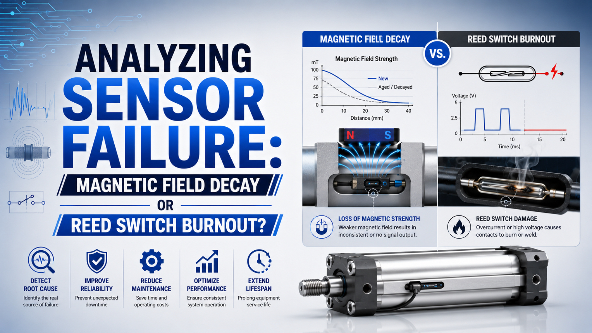
Pneumatic cylinder sensor failure is a missing, stuck, delayed, or unstable position signal in the actuator’s control chain. It should not be diagnosed as a simple choice between magnetic field decay and Reed switch burnout. The fault can originate in the sensor, cable, connector, input circuit, mounting position, piston motion, magnetic path, or piston magnet.
A known-good sensor swap is useful, but it is not a verdict by itself. If the fault stays at one cylinder position, the cause could still be the sensor slot, local wiring, piston stop position, bracket, external steelwork, or magnetic margin. A gauss reading is meaningful only when its probe orientation, distance, location, temperature, and healthy reference are controlled.
For sensor technology and wiring selection, use the separate Reed, Hall, and MR cylinder-switch guide. For magnet geometry and switching-point accuracy, see the internal piston magnet design guide.
Publisher and author information is available on About Us. Send technical corrections or application questions through Contact.
Key Takeaways
- Diagnose the signal chain before blaming the magnet.
- Verify actual piston arrival and sensor mounting before electrical replacement.
- Test Reed contacts and electronic sensors by their own wiring diagrams.
- Compare magnetic readings with an identical healthy axis under controlled geometry.
- Use model-specific voltage, current, operating-range, hysteresis, and temperature limits.
Why Is “Magnetic Decay or Reed Burnout” an Incomplete Diagnosis?
One SMC auto-switch guide gives reference hysteresis of 2 mm or less for covered Reed families and 1 mm or less for covered solid-state families, while warning that environment can change the result (SMC Auto Switch Guide, accessed 2026). A missing signal therefore describes a system symptom, not one failed component.
A cylinder switch sits inside a chain with at least five fault domains:
- Controller and power: PLC input configuration, common reference, input filter, supply voltage, and diagnostic state.
- Cable and connector: broken conductor, loose pin, damaged jacket, oil ingress, incorrect pinout, or intermittent flex failure.
- Sensor package: Reed contact, indicator circuit, Hall or MR element, comparator, transistor output, and internal protection.
- Mechanical interface: sensor position, tightening torque, slot compatibility, cylinder wall, bracket, piston arrival, and rebound.
- Magnetic path: piston magnet position, magnetization, temperature history, surrounding ferrous material, external field, and sensing margin.
The observed failure mode does not map one-to-one to those domains. A welded Reed contact may hold the input ON. A broken cable or failed-open contact may hold it OFF. Marginal magnetic coupling may chatter at one speed yet work during a slow manual stroke. Incorrect polarity can also produce a confusing combination of switch and indicator behaviour on some packaged devices.
| Observed symptom | Strong first check | Do not conclude yet |
|---|---|---|
| Sensor indicator changes, PLC input does not | Measure signal at sensor, connector, terminal, and PLC input | The magnet is weak |
| Indicator never changes | Verify supply, wiring, sensor position, and piston arrival | The sensor is burned out |
| Input remains ON | Check wiring, output topology, welded contact, leakage, and nearby magnetic field | The PLC input card has failed |
| Works during slow jogging only | Record production speed, dwell, switch window, rebound, and PLC filter | Magnetic field has decayed |
| New sensor fails in the same place | Verify compatibility, mounting, wiring route, piston position, and magnetic margin | The magnet is proven defective |
| Fault follows the sensor to another position | Inspect sensor, cable, connector, and electrical load | Every other interface is healthy |
The useful question is not “Which of two parts failed?” It is “At which interface does the expected state stop propagating?” That wording turns a component guess into a reproducible fault-isolation test.
The 5-Stage Isolation Test Locates the Failed Interface
For one SMC cylinder and switch combination, the D-A93 Reed switch is specified at 24 VDC with a 5 to 40 mA load-current range. The same catalog calls its mounting dimensions a guide and requires confirmation in actual operation (SMC CDU catalog, 2026). Electrical compatibility and physical commissioning must therefore be checked together.
Before testing, follow the machine’s energy-isolation procedure. Depressurize or restrain motion when the task requires access to the actuator. Never perform resistance or continuity testing on an energized circuit, and do not bypass a safety function to make a production sensor change state.
Stage 1: Confirm the PLC and supply state
Read the sensor indicator, PLC input LED, software input bit, and sequence state at the same time. Record supply voltage and signal voltage using the sensor’s wiring diagram. A signal present at the sensor but absent at the PLC narrows the fault to the connector, cable, terminal, common reference, input channel, or configuration.
If the PLC input changes but the sequence does not advance, the cylinder sensor may be healthy. Check interlocks, timers, edge detection, input filtering, and the expected transition in the program. This is a control-logic problem until evidence says otherwise.
Stage 2: Prove that the piston reaches the sensing position
Jog the cylinder at a controlled speed and verify the mechanical endpoint or intended sensing zone. Look for insufficient pressure, restricted exhaust, changed load, misadjusted cushioning, external stops, rebound, side load, or contamination. A sensor cannot confirm an endpoint the piston never reaches.
Use an independent mechanical reference when practical. Mark the normal stop position, use a dial indicator for a repeatable test, or compare the carriage with an identical working axis. Do not infer piston position only from the failed sensor.
Stage 3: Inspect the sensor-to-cylinder interface
Confirm the exact sensor part number, cylinder family, approved mounting hardware, slot orientation, tightening method, and cable exit. Move the sensor slowly through the expected operating window and mark the ON and OFF positions from both approach directions. A narrow, displaced, or inconsistent window is evidence, but it is not yet proof of magnet decay.
Nearby steel brackets, covers, tie rods, welding conductors, or another strong magnet can alter the local field. Temporarily reproduce the healthy mechanical arrangement before comparing results.
Stage 4: Perform a controlled known-good swap
Use a compatible, verified sensor with the same output type and wiring. Test the suspect sensor at a known-good position, then test the known-good sensor at the suspect position. Keep the connector, input channel, mounting hardware, and test method under control so the swap changes only one variable at a time.
Stage 5: Compare the magnetic path
Only after the first four stages should the magnetic path become the leading suspect. Compare the suspect location with an identical healthy cylinder using the same sensor or magnetic probe, orientation, stand-off, piston position, temperature, and nearby hardware. A repeatable reduction under matched conditions supports a magnetic-path diagnosis.
In our experience reviewing applications, the fastest diagnosis usually comes from writing down the expected signal at each interface before touching a component. That prevents a new sensor from temporarily hiding a loose connector, a shifted stop, or a marginal operating window.
How Can Reed Switch Burnout Be Confirmed Safely?
Standex reports 50 to 200 million operations for one 10 V, 10 mA test condition, yet warns that inductive loads can sustain arcing as contacts open (Standex Load Switching and Contact Protection, accessed 2026). Reed service life is therefore load- and circuit-dependent, not a universal cycle count.
A bare Reed element is a magnetically operated mechanical contact. A packaged cylinder switch may also contain an indicator, resistor, surge suppressor, polarity-sensitive circuit, or connector. Obtain the exact circuit diagram before choosing a test.
For a compatible unpowered dry-contact device:
- Isolate electrical power and disconnect the switch from the control circuit.
- Select the appropriate resistance or continuity range.
- Measure the contact state with the actuating field absent.
- Apply the specified magnetic target or move the piston into the operating zone.
- Repeat the test several times and flex the cable gently at normal strain-relief points.
Possible evidence includes:
- Always open: broken conductor, failed-open contact, incorrect test geometry, or insufficient operating field.
- Always closed: welded contact, normally closed device, external field, or incorrect wiring interpretation.
- High or unstable closed resistance: damaged contact, cable, connector, probe connection, or contaminated terminal.
- Normal bench switching but failed installed signal: mounting, magnetic compatibility, field margin, voltage, load, connector, or PLC interface.
Do not apply this ohmmeter method to a powered two-wire electronic sensor or a three-wire PNP/NPN device as though it were a dry contact. Electronic outputs require supply voltage and a compatible test load. Also account for internal voltage drop and off-state leakage where the data sheet specifies them.
Reed burnout is not limited to excessive steady current. Relay coils and solenoids can generate an inductive voltage transient when the contact opens. Capacitive loads and long cables can create closing inrush. Use the switch manufacturer’s recommended diode, RC network, varistor, interface relay, or electronic input arrangement for the actual AC or DC load. Do not copy a generic protection circuit without checking polarity and release-time consequences.
How Should Magnetic Field Decay Be Evaluated?
VACUUMSCHMELZE states that 1 tesla equals 10 kilogauss and explains that a temperature-driven flux change can be reversible while a magnet remains on the linear portion of its demagnetization curve. Outside that region, loss can become irreversible (VACODYM and VACOMAX technical brochure, accessed 2026). Temperature history alone does not prove permanent magnetic decay.
A handheld gauss meter measures magnetic flux density at its probe, not “magnet health” as a universal percentage. The reading changes with:
- probe axis and polarity;
- probe-to-cylinder distance;
- axial position relative to the piston;
- cylinder wall and slot geometry;
- magnet arrangement and orientation;
- nearby ferrous parts or external fields;
- temperature of the magnet, cylinder, and probe;
- meter range, zeroing, calibration, and repeatability.
For that reason, an isolated value such as 400 gauss has no general pass/fail meaning for pneumatic cylinders. Compare against the cylinder and switch manufacturer’s operating data or against an identical healthy assembly. Keep the measurement geometry fixed with a nonmagnetic fixture or spacer, and record the maximum, minimum, location, direction, and temperature.
Run the comparison at several controlled piston positions rather than searching blindly for one peak. If the field pattern shifts along the cylinder while its magnitude remains comparable, suspect piston position, magnet retention, measurement geometry, or assembly differences. If the entire repeatable profile is lower on the suspect axis, magnetic margin becomes a stronger lead.
A magnetic baseline should be treated like a calibrated fixture result, not a magic number. The comparison becomes useful when the same sensor or probe, same position, same stand-off, same orientation, and same environment produce a repeatable difference.
What Does the Signal Pattern Say About the Corrective Action?
SMC lists a 24 VDC, 5 to 40 mA load-current range for one D-A93 Reed application and warns that mounting dimensions still require operating confirmation (SMC CDU catalog, 2026). Corrective action must therefore address both the measured fault and the exact sensor-cylinder-control combination.
| Evidence pattern | Most likely fault domain | Corrective action |
|---|---|---|
| Correct output at sensor, missing at PLC | Cable, connector, terminal, common, or PLC channel | Repair the interrupted interface; verify the input under motion |
| PLC input changes, sequence remains stopped | Program, interlock, filter, timing, or state logic | Correct the control condition; retain the proven sensor |
| Piston stops outside the operating window | Pneumatic or mechanical motion | Correct pressure, flow, load, stop, cushioning, or alignment |
| Fault follows one sensor and its cable | Sensor package or cable | Replace with an approved equivalent; inspect electrical stress |
| Reed contact welded or degraded | Load or transient stress | Replace the switch and correct the load/protection circuit |
| Known-good sensor works only after repositioning | Mounting window or compatibility | Set and lock the operating position; verify both directions |
| Matched field profile is reduced after other layers pass | Magnet, retention, geometry, or temperature history | Consult cylinder data; repair or replace the validated internal part |
| Multiple axes fail near welding equipment | External field or installation environment | Use an approved field-resistant solution and revalidate the layout |
Replacing a Reed switch without correcting its load can repeat the failure. Replacing a piston magnet without proving sensor compatibility can leave the signal unchanged. Replacing the PLC input before tracing voltage can simply move the downtime.
Record the evidence before and after correction:
- machine and cylinder identification;
- cylinder and sensor part numbers;
- wiring topology and PLC input;
- supply, load, and measured signal voltage;
- ON and OFF positions from both travel directions;
- piston speed, load, pressure, and stop position;
- ambient and cylinder temperature;
- connector and cable condition;
- magnetic comparison geometry and healthy reference;
- corrective action and production verification result.
If repeated impacts have shifted the sensing window or damaged internal parts, inspect the actuator’s stopping behaviour. The pneumatic cushioning failure guide covers the mechanical side. If magnetic switches remain unsuitable for the environment, compare alternative technologies in the pneumatic cylinder position-sensing guide or consider differential-pressure end-of-stroke sensing where its limitations fit the application.
Pneumatic Cylinder Sensor Failure FAQs
SMC warns that auto-switch hysteresis can vary with the operating environment, even though one guide gives family reference values of 2 mm or less for Reed switches and 1 mm or less for solid-state switches (SMC Auto Switch Guide, accessed 2026). The following answers keep diagnosis tied to measured evidence.
Does a fault staying at one cylinder position prove magnetic field decay?
No. It proves only that the fault did not follow the swapped sensor under that test. The remaining causes include local wiring, connector position, sensor slot, bracket movement, piston travel, stop position, external steelwork, magnetic compatibility, magnet retention, and field strength. Isolate those variables before condemning the piston magnet.
Can every cylinder sensor be checked with a continuity meter?
No. A compatible, isolated dry-contact Reed switch can be tested for open and closed resistance according to its diagram. Two-wire electronic sensors and three-wire PNP or NPN devices require the correct supply and load. Applying an ohmmeter method without identifying the output circuit can produce a false diagnosis or damage.
Why does the sensor indicator change while the PLC input stays off?
The local sensing stage may be working while the signal is lost downstream. Measure at the sensor output, connector, terminal strip, and PLC channel. Check the common reference, two-wire internal voltage drop, output topology, connector pinout, damaged conductor, input threshold, and software state before replacing the cylinder sensor.
Is there a universal gauss value for a healthy pneumatic cylinder magnet?
No. The reading depends on probe axis, gap, piston position, cylinder construction, magnet arrangement, temperature, nearby steel, and meter setup. Use manufacturer data or an identical healthy assembly. Compare the complete field or switching-window profile under fixed geometry rather than applying a generic gauss percentage to every actuator.
When should the piston magnet or cylinder be replaced?
Replace it after compatible sensors, wiring, PLC input, mounting, piston arrival, and local interference have passed controlled checks, yet a matched comparison still shows inadequate magnetic margin. Confirm whether the magnet, its retention, or another internal part is serviceable. Then validate the repaired assembly through the full production motion.
Sources and technical references
- SMC Auto Switch Guide, terminology and hysteresis reference, accessed 2026-07-26.
- SMC Free Mount Cylinder CDU Catalog, model-specific switch and mounting data, 2026, accessed 2026-07-26.
- SMC D-A93 Web Catalog, accessed 2026-07-26.
- Standex MEDER, Load Switching and Contact Protection, accessed 2026-07-26.
- VACUUMSCHMELZE, Rare-Earth Permanent Magnets VACODYM and VACOMAX, accessed 2026-07-26.
- Festo, Cylinder Sensors, accessed 2026-07-26.