

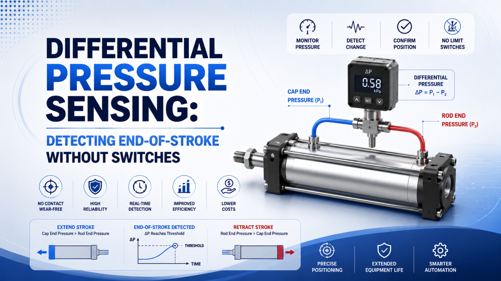
Differential pressure sensing can identify a repeatable pressure event associated with a pneumatic cylinder reaching the end of commanded travel. It does not see the piston. The controller compares both port pressures, direction, timing, and operating limits to infer that motion has ended. This can remove cylinder-mounted position switches from some non-safety sequences, but pressure sensors and logic are still required. A jam, workpiece contact, blocked exhaust, or heavy cushioning can resemble an end stop. The real question is whether a validated pressure signature can serve as a dependable process event for one defined machine state.
Key Takeaways
- A 1997 patent trips on a preset pressure crossover, not direct piston position.
- Calibrate extension and retraction separately under real load and supply variation.
- Treat jams, blocked exhaust, leaks, cushioning, and sensor faults as explicit diagnostic states.
What Does Differential Pressure Sensing Actually Detect?
Filed in 1995 and issued in 1997, a US patent describes a pneumatic end-of-stroke device that compares supply-side and exhaust-side pressures against an adjustable crossover point (US5587536A). The output therefore represents a pressure-defined event, not an independent measurement of piston coordinates.
Differential pressure sensing is the comparison of pressure at the two working ports of a double-acting cylinder. During a commanded stroke, driving pressure normally exceeds exhaust pressure. When motion stops and the valve remains energized, the driving chamber may approach supply pressure while the other chamber vents. The resulting signature answers whether the pneumatic state matches a commissioned end-event pattern. It does not provide a piston coordinate, and an obstruction elsewhere can create the same force balance.
That distinction changes the PLC design. Pressure evidence becomes stronger when:
- the commanded direction agrees;
- elapsed time, both sensor channels, and supply pressure remain inside their valid windows;
- an independent position reference confirms during commissioning that the complete signature corresponds to the intended endpoint across the operating envelope, including the minimum supply, highest expected load, slowest valid motion, and final cushion settings.
Otherwise, the pressure event should produce a fault. Pressure-based detection is strongest when the machine needs confirmation of a repeatable pneumatic event, while direct sensors remain clearer for intermediate position, tight geometric tolerances, or personnel-protection functions. Name the PLC state pressure_end_candidate, not cylinder_extended, until the remaining conditions pass. This prevents downstream logic from treating an inferred pneumatic state as a direct geometric measurement. The underlying force relationship is explained in how pressure differential creates pneumatic force.
Pressure Signatures During a Cylinder Stroke
One 2020 experimental study notes that cylinder chamber pressure stays below supply pressure during motion and rises to its maximum only after the cylinder reaches its final position (Energies). That behavior creates a useful end-event signature, but its shape still depends on load, valve flow, cushioning, and exhaust restriction.
Read each pressure trace as a sequence, not as one isolated sample:
| Stroke phase | Typical trace behavior | Why it is not a position measurement |
|---|---|---|
| Valve switching | Both port signals change before useful velocity develops | Valve and tube dynamics precede significant motion |
| Acceleration | Driving pressure and exhaust backpressure rise | Load, friction, and restrictions shape both signals |
| Travel | Differential pressure supplies net force | The same value can occur at many locations |
| Cushion entry | Restricted exhaust can raise backpressure | Cushion resistance can resemble external load |
| Stop or contact | Velocity falls and driving pressure can climb | Cap contact, workpiece contact, and jams can look alike |
| Dwell | Pressure settles with leakage and trapped volume | Settled pressure does not locate the piston |
An extending single-rod cylinder has this simplified force balance:
Here, is net axial force in newtons; and are gauge pressures in pascals; and are effective areas in square meters; and is seal and guide friction in newtons. Single-rod areas are unequal, while load, friction, and backpressure can change anywhere in the stroke. The equation supports force diagnosis, not position conversion. See cylinder force loss from friction and backpressure for the full measurement method.
How Should Differential Pressure Be Calculated and Normalized?
Issued in 1997, the differential-pressure patent compares the pressure line feeding one chamber with the line exhausting the other, then changes output when their difference crosses an adjustable trip point (US5587536A). Modern PLC logic can retain both raw signals and normalize them instead of relying on one fixed bar value.
With two gauge-pressure measurements, define the signed port difference as:
Here, is instantaneous port-pressure difference, while and are measured at ports A and B. Use one unit. The sign represents direction only after defining valve command and cylinder orientation.
To compare extension and retraction with one positive-going signal, use a direction sign:
A direction-normalized pressure ratio is the dimensionless value . Here, is $+1$ for the defined A-driving direction and $-1$ for the opposite direction, while is measured supply gauge pressure. The method assumes valid supply and compatible sensor references. Normalization reduces sensitivity to slow supply changes, but cannot remove load, flow, temperature, leakage, or sensor errors.
Use several features together:
| Feature | Control purpose | Main limitation |
|---|---|---|
| Direction-adjusted | Compare both directions with positive-going values | Still changes with load and restriction |
| Pressure slope | Separate a rise from a plateau | Depends on sampling and filtering |
| Minimum dwell | Reject brief spikes | Adds delay |
| Command-to-event time | Reject early or late events | Needs a commissioned timing envelope |
| Signal plausibility | Block invalid measurements | Needs separate fault limits |
Extension and retraction should have separate envelopes even after normalization. The rod changes effective area, valve paths may not be symmetrical, meter-out controls can differ, and gravity may assist one direction. One universal threshold hides these real asymmetries.
Which Conditions Create False End-of-Stroke Signals?
US5587536A states that the “effective end of stroke” can occur anywhere along piston travel depending on increasing pressure in one line and decreasing pressure in the other (Google Patents). This is the central diagnostic limitation: the pressure crossover identifies a force-and-flow condition, not necessarily contact with the cylinder cap.
Suppose the rod contacts a fixture before the expected endpoint. Driving pressure can rise while exhaust pressure falls, so the controller may see a convincing candidate event. A binding slide or oversized workpiece can produce the same pattern. This is one practical example of why timing belongs in the acceptance logic.
| Condition | Pressure effect | Correct controller response |
|---|---|---|
| Jam or premature contact | Driving pressure rises while motion stops early | Reject events outside the valid timing window |
| Cushion or meter-out restriction | Exhaust backpressure changes near stroke end | Commission with final settings |
| Restricted valve exhaust | Exhaust pressure stays high | Diagnose backpressure before changing thresholds |
| Supply-pressure loss | The expected difference may not develop | Raise a supply fault at timeout |
| Leakage | Pressure rises slowly or decays | Test leakage before recalibrating |
| Long sensing tubes or heavy filtering | The event becomes delayed and rounded | Verify the complete response delay |
| Sensor or wiring fault | The calculated difference stays falsely high or low | Apply range, rate, and agreement checks |
Therefore, the PLC should treat differential pressure as one state-machine input. A useful decision path is shown below.
Backpressure mechanisms are covered in how pneumatic backpressure affects equipment. Cushion behavior requires its own review; see how pneumatic cylinder cushioning works.
Sensor Architecture and PLC Logic
Parker’s pneumatic pressure-sensor catalog states that sensor response is typically below 2.0 ms and can be intentionally slowed by programmable response settings (Parker Pneumatic Pressure Sensors). That is a model-specific electrical response, not the total delay through tubing, filtering, PLC sampling, logic, and chamber dynamics.
Three sensing architectures are practical:
| Architecture | Strengths | Design checks |
|---|---|---|
| Two gauge-pressure transmitters | Preserves both chamber traces, supports supply/exhaust diagnostics, and allows software calculation | Requires two channels, matched ranges, offset checks, and synchronized sampling |
| One bidirectional differential sensor | Produces the difference directly with one measurement channel | Must tolerate the common-mode pressure, both polarities, expected overload, and port reversal |
| Two digital pressure switches | Simple discrete wiring and local hysteresis | Hides waveform detail and makes adaptive or normalized logic more difficult |
At the cylinder port, a sensor sees local chamber pressure more directly. At the valve manifold, its reading includes tube pressure loss and stored volume. Long narrow sensing lines add lag and can trap condensate. Follow the sensor’s media, overpressure, temperature, orientation, and mounting limits.
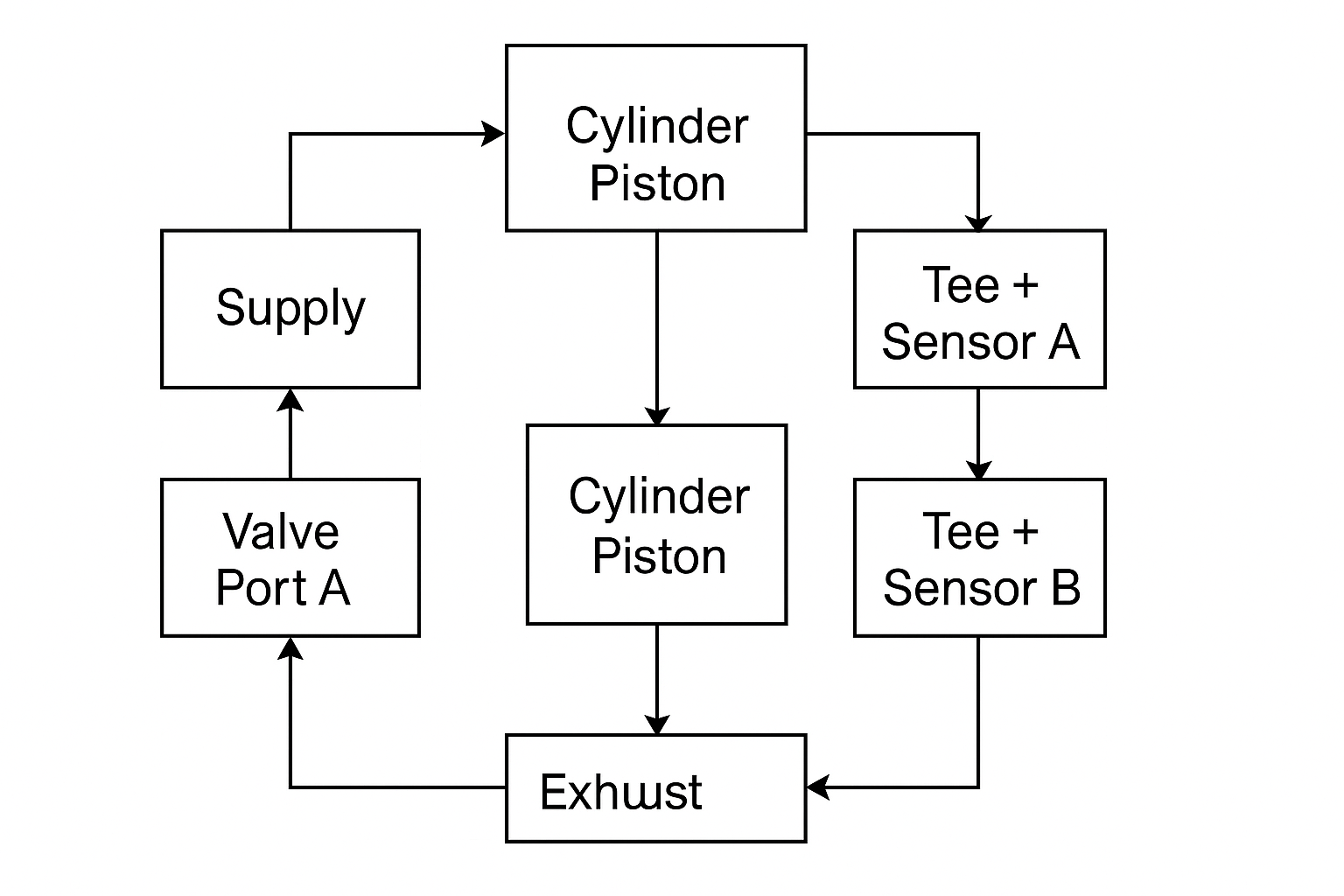
Dual-channel sensing preserves both port pressures for PLC diagnostics. The drawing shows topology only; final porting, sensor range, and electrical interface must follow the selected components.
PLC logic should use explicit states rather than one free-running comparator:
- Idle: verify both channels before motion.
- Moving: select the direction-specific pressure and timing envelope.
- Candidate: start dwell only after every condition becomes true.
- Confirmed: latch the event while command and hold conditions remain valid.
- Fault: separate early, late, missing, and invalid-signal outcomes.
Do not keep the state latched after exhaust, supply loss, or possible external movement. Define reset and plausibility conditions.
How Do You Commission the Detection Window?
IFM’s PN2571 lists a response time below 1.5 ms, programmable switch delays from 0 to 50 s, and process-value damping from 0 to 4 s (ifm PN2571). Those adjustable values show why commissioning must document the complete signal chain rather than assume one universal debounce time.
Commissioning envelope means the accepted range of pressure ratio, slope, timing, and dwell for a defined machine state. Establish it with the final cylinder, valve, tubing, silencers, controls, cushion settings, moving mass, and supply arrangement. An unloaded bench threshold can fail after the mechanism is connected.
Use this sequence:
- Install a temporary direct position reference so each captured pressure event has an independent truth label.
- Record synchronized , , supply pressure, valve command, reference state, and event time at the real PLC sampling rate.
- Exercise the expected load, speed, supply, direction, temperature, dwell, cushion, and mechanical variation.
- Build separate extension and retraction envelopes for pressure ratio, slope, event time, and dwell, including measurement uncertainty.
- Set hysteresis and filtering without hiding the fastest valid event or delaying fault response.
- For example, challenge restricted exhaust, reduced supply, safe intentional obstruction, sensor disconnection, and representative leakage.
- Define early, valid, and late windows, then save accepted traces, parts, settings, software revision, and test conditions.
Acceptance should cover more than successful cycles:
| Test group | Evidence to retain |
|---|---|
| Normal operation | Pressure traces and direct-position agreement |
| Timing margins | Earliest and latest valid events plus signal-chain delay |
| Sensor faults | Open, shorted, frozen, saturated, or offset signal response |
| Pneumatic faults | Low supply, high exhaust pressure, leakage, or valve fault |
| Mechanical faults | Premature contact, binding, stall, or incomplete return |
Good commissioning records store the shape and context of the event, not just the final threshold. When cycle behavior changes later, maintenance can compare timing, slope, plateau, and channel agreement to distinguish mechanical drag from air-supply or sensor problems.
When Should You Keep Physical Position Sensors?
ifm states that its IO-Link cylinder sensors can provide continuous piston-location measurement for short strokes of 50 mm or less, while standard cylinder sensors directly detect the piston magnet through the barrel (ifm Cylinder Sensors). That is a direct position-sensing function, unlike inference from chamber pressure.
Choose the sensing method from the required evidence:
| Requirement | Differential-pressure event | Cylinder switch | Continuous position sensor |
|---|---|---|---|
| Confirm a repeatable stop/contact event | Suitable after validation | Checks the configured location | Suitable but may be unnecessary |
| Detect an intermediate point | Poor fit | Suitable for discrete locations | Best for a continuous coordinate |
| Separate end contact from an earlier jam | Needs timing or process evidence | Checks the configured location | Shows measured position |
| Diagnose pressure and load | Strong with both port traces | No pressure information | Needs separate pressure sensing |
| Safety-related confirmation | Requires a validated safety function | Requires a safety-rated architecture | Requires a safety-rated architecture |
Keep direct sensing when the piston must cross a specific location, intermediate states matter, or an obstruction can imitate the expected pressure event. Pressure sensing fits mechanically repeatable endpoints where an inferred event is acceptable and both chamber traces also support diagnostics. During a retrofit, compare what the existing switch proves with what the pressure event can actually prove; wiring reduction alone is not a sufficient acceptance criterion. A hybrid design can retain one direct endpoint channel while using both pressure traces for timing, leakage, and restriction diagnostics. For example, if the old switch proves that a mechanism cleared a protected space, preserve that direct evidence unless the safety design is validated. If it only confirms loading against a fixed stop in a sequence, a commissioned pressure event may be an appropriate replacement. Compare the reed and Hall-effect sensor guide and the cylinder drift procedure before selecting the architecture.
Differential Pressure Sensing FAQs
In 2015, a study reconstructed pneumatic piston position at standstill from two chamber-pressure measurements, but required signal injection and a nonlinear observer rather than a simple threshold (Control Engineering Practice). The distinction helps answer what pressure-only end detection can and cannot prove.
Can differential pressure prove that the piston reached the mechanical end cap?
No. The 1997 differential-pressure patent changes output at a preset pressure crossover and notes that an effective endpoint can occur elsewhere along the travel. A jam, workpiece contact, cushion restriction, or blocked exhaust can imitate the signal. Use direction, timing, sensor-health checks, and an independently validated commissioning reference.
Is one differential sensor better than two pressure transmitters?
It depends on the diagnostic requirement. One bidirectional differential sensor provides a compact signal, but two transmitters preserve both chamber pressures and make supply, exhaust, leakage, and channel faults easier to separate. Confirm common-mode rating, overload, accuracy, sampling, tubing volume, and electrical interface for the selected architecture.
How should the PLC threshold be selected?
Do not copy a generic 4–6 bar value. Record both chamber pressures with a direct position reference across the expected load, speed, supply, temperature, and cushion settings. Build separate extension and retraction envelopes, then validate ratio, slope, dwell, early-event timing, and timeout behavior under normal and selected fault conditions.
Can pressure detection replace a safety-rated end-position switch?
Not by default. A normal pressure sensor, PLC comparator, and threshold do not become a safety function merely because two pressure channels are used. If position participates in personnel protection or risk reduction, the complete sensing, logic, diagnostics, fault response, and validation must meet the machine’s required safety design.
Sources and technical references
Differential Pressure Sensing Device for Pneumatic Cylinders; Piston Position Estimation at Standstill; Cylinder Pressure at Final Position; Parker Pneumatic Pressure Sensors; ifm PN2571 Pressure Sensor; and ifm Cylinder Sensors.