

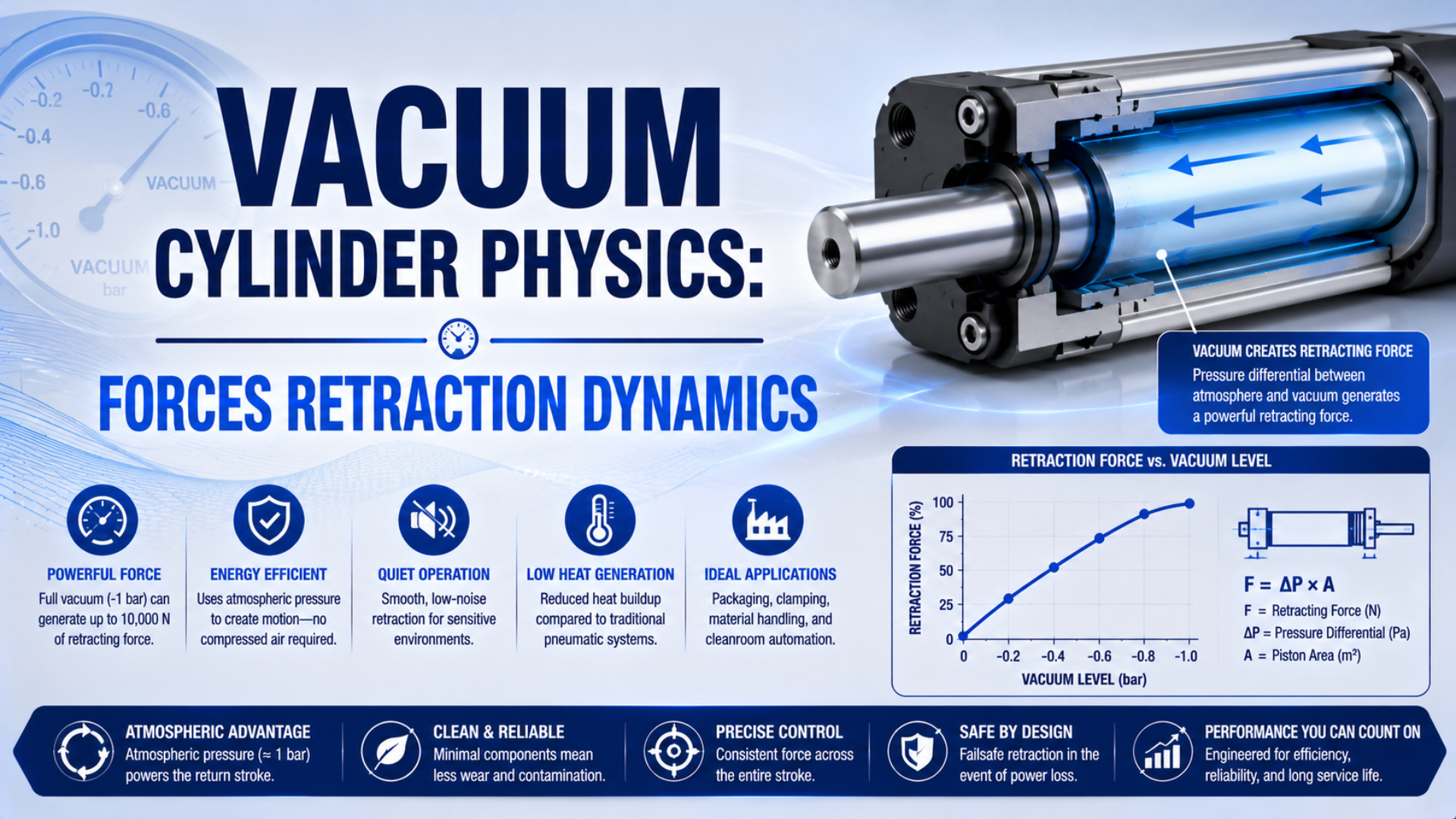
A vacuum cylinder moves because unequal absolute pressures act on defined areas of its piston-and-rod assembly. Vacuum doesn’t pull the piston by itself. The higher-pressure side pushes toward the lower-pressure side, while seal friction, the external load, chamber geometry, local atmospheric pressure, and the vacuum source determine whether motion starts and how quickly it develops.
That distinction matters because “vacuum cylinder” describes more than one product architecture. Some devices retract when a chamber is evacuated. Others extend first and retract only after a suction cup seals against a workpiece. Start with the actual section drawing and port sequence, then calculate force and response for that configuration.
Key Takeaways
- Standard atmosphere is 101.325 kPa, but local ambient pressure is the real force boundary.
- Vacuum connection, piston geometry, and external rod pressure determine motion direction.
- Static pressure-area force cannot predict stroke time without flow, volume, leakage, and load data.
- Use absolute pressure throughout the calculation.
What Is a Vacuum Cylinder, and Does Vacuum Always Cause Retraction?
Schmalz lists two HS vacuum lifting-cylinder strokes, 14 mm and 28 mm, and states that applying vacuum extends the rod before workpiece contact causes retraction. That real product sequence disproves any universal rule that vacuum always retracts a piston (Schmalz HS vacuum lifting cylinders, retrieved 2026).
A vacuum cylinder is an actuator whose motion sequence uses pressure below the surrounding absolute pressure. The term alone doesn’t identify which chamber is evacuated, which piston area is active, whether a spring contributes force, or whether a suction cup changes the circuit after contact.
Three devices are often given the same informal name:
| Architecture | What vacuum does | What determines the return motion |
|---|---|---|
| Vacuum-actuated piston cylinder | Evacuates one working chamber so pressure on the other side drives the piston | Port location, piston areas, external rod pressure, spring, load, and friction |
| Vacuum lifting cylinder | Coordinates a short piston stroke with suction-cup contact | Internal geometry, workpiece sealing, spring or pressure sequence, and manufacturer design |
| Pneumatic cylinder with a hollow rod | Carries vacuum through the rod to a gripper while compressed air drives the piston | Normal pneumatic valve and cylinder circuit |
That third design is especially easy to misread. A hollow rod carrying vacuum doesn’t prove that vacuum drives the cylinder. Confirm whether the vacuum line acts on the piston or simply passes through it to a cup.
Operationally, trace each pressure boundary at every stage of the cycle. Mark the cap chamber, rod chamber, exposed rod end, vacuum source, atmosphere connection, check valve, and any spring. The actuator’s commercial name is secondary to that pressure map.
Pressure Forces on a Single-Rod Vacuum Cylinder
NIST defines one standard atmosphere as exactly 101.325 kPa, while Parker calculates single-rod cylinder force from the separate pressure and effective area on each side. Those two facts establish the correct method: use absolute pressures and sum every pressure-area force before subtracting friction and load (NIST; Parker).
Choose extension as the positive direction. For a piston diameter and rod diameter , the areas are:
is the full piston area, is the rod cross-sectional area, and is the annular area in the rod chamber. Use square metres with pascals to obtain newtons. The piston-rod area guide explains the same geometry for conventional cylinders.
With a rod exposed to an outside absolute pressure , the pressure contribution to the piston-and-rod assembly is:
is cap-chamber absolute pressure, is rod-chamber absolute pressure, and is the absolute pressure acting on the external rod end. The signs follow the chosen extension-positive convention.
The signed motion equation is:
and are signed forces on the assembly. Friction opposes impending or actual motion, so its sign reverses with direction. For a selection check in one known direction, use magnitudes:
Don’t assign a universal friction percentage. Use manufacturer minimum operating pressure, measured breakaway force, or a validated test value. The distinction between static and moving resistance is covered in the breakaway-force guide.
When does cap-side vacuum cause retraction?
If the cap chamber is evacuated to , while both the rod chamber and exposed rod end are at the same ambient pressure , the force simplifies to:
This full-area result is valid for that stated boundary condition. It isn’t permission to use full piston area for every vacuum circuit.
When does rod-side vacuum cause extension?
If the rod chamber is evacuated to , while the cap chamber and exposed rod end are both at ambient pressure , the extension force becomes:
Here the annular area matters. A sealed rod enclosure, differential piston, double rod, spring, or non-atmospheric opposing chamber changes the equation, so return to the complete pressure balance whenever the physical boundary differs.
How Much Theoretical Force Can Bore Size Produce?
At an 85 kPa pressure difference, a 25 mm piston develops 41.7 N theoretically, while an 80 mm piston develops 427.3 N. The 10.24-fold force ratio comes directly from the squared diameter ratio, not from a generic “50 to 500 N” product rule (NIST standard-atmosphere definition).
For the cap-vacuum boundary defined above:
is local ambient absolute pressure minus vacuum-chamber absolute pressure. The table uses and does not apply an invented efficiency factor.
| Bore diameter | Full piston area | Theoretical force at 85 kPa |
|---|---|---|
| 25 mm | 491 mm² | 41.7 N |
| 32 mm | 804 mm² | 68.4 N |
| 40 mm | 1,257 mm² | 106.8 N |
| 50 mm | 1,963 mm² | 166.9 N |
| 63 mm | 3,117 mm² | 264.9 N |
| 80 mm | 5,027 mm² | 427.3 N |
Doubling bore quadruples theoretical pressure force because area scales with . A 63 mm bore has 3.88 times the full piston area of a 32 mm bore, which is more precise than calling the result “approximately four times” without showing the two actual diameters.
Maximum theoretical vacuum force also has a hard environmental ceiling. Even a perfect zero-absolute-pressure chamber can supply only local ambient pressure as . A conventional pneumatic cylinder operating at several bar gauge can therefore produce much more force from the same bore, although its energy use and failure behavior are different.
Worked force example
Consider a 40 mm piston with cap-chamber vacuum. The measured local ambient pressure is 95 kPa absolute, and the cap chamber reaches 20 kPa absolute. The pressure difference is:
Theoretical retraction force is:
Suppose a controlled breakaway test for the assembled actuator and guide measured 12 N of opposing friction, while the external resisting load is 45 N. The initial net force estimate is:
That result indicates a positive starting margin under the measured condition. It doesn’t prove acceptable stroke time, stability, seal life, end-of-stroke energy, or behavior at the lowest expected ambient pressure. Those require separate checks.
Static Force Versus Retraction Time
Leybold’s fixed-volume equation shows that reducing pressure from 101.325 kPa to 20 kPa requires ideal time constants when effective pumping speed stays constant. A moving cylinder breaks the fixed-volume assumption because piston travel changes chamber volume while gas is still leaving (Leybold).
A common fixed-volume estimate is:
is evacuation time, is fixed system volume, is effective pumping speed at the chamber, and and are starting and target absolute pressures. Units for and must be compatible.
Leybold states that this simplification assumes constant suction speed and omits conductance, thermal effects, and desorption. In industrial ejector circuits, leakage and the pressure-dependent suction-flow curve add further error. Festo also defines total vacuum-system volume as the combined volume of the cup, holder, and tubing, illustrating why the device chamber alone is insufficient (Festo vacuum principles).
Moving chamber geometry can be represented as:
is dead volume at the reference position, is the active chamber area, and is piston displacement in the direction that increases the evacuated volume. Reverse the sign if the chamber shrinks during the selected motion.
Piston motion still follows:
is the equivalent moving mass. Chamber pressure changes the force, motion changes chamber volume, and volume changes the pressure response. That feedback is why a fixed “initial evacuation, peak velocity, final positioning” timeline cannot be transferred from one machine to another.
As a first estimate, use the calculator on the stationary dead volume before motion or on a genuinely fixed chamber. Then validate the moving stroke with the selected ejector or pump curve and measured pressure traces.
Positive-pressure circuits have the same coupling, as explained in the cylinder response-time and dead-volume guide. Vacuum analysis reverses the flow direction but still requires actual volume, conductance, and changing chamber pressure.
Which Variables Control Breakaway, Acceleration, and Final Speed?
SMC’s current ZR ejector range lists maximum suction flows from 25 to 95 L/min across five nozzle sizes, a 3.8-to-1 spread within one product family. That variation shows why a generic pump-flow range cannot determine cylinder response without an exact model and operating point (SMC ZR specifications).
Retraction begins only when the pressure force exceeds every opposing force at rest:
Once the piston moves, the resistance may fall to a different running-friction value. Acceleration then follows net force divided by equivalent moving mass. A deeper vacuum can increase pressure force, but it doesn’t guarantee a proportionate speed increase because the source may supply less suction flow as absolute pressure falls.
Group the required inputs by their physical role:
| Group | Required data | Why it matters |
|---|---|---|
| Pressure boundary | Local ambient, both chamber pressures, outside rod pressure | Establishes instantaneous pressure force and direction |
| Geometry | Bore, rod diameter, chamber dead volume, stroke | Establishes effective area and changing volume |
| Vacuum source | Suction-flow curve, supply pressure, ultimate pressure, duty | Establishes how quickly gas can leave at each pressure |
| Flow path | Valve conductance, tube ID and length, fittings, filter, silencer | Reduces effective flow at the chamber |
| Mechanics | Breakaway friction, running friction, guide drag, load, orientation | Establishes start threshold and moving resistance |
| Dynamics | Moving mass, external forces, cushion, stop | Establishes acceleration and end-of-stroke behavior |
| Leakage | Measured gas load or pressure-rise rate | Raises achievable pressure and extends evacuation time |
Don’t convert a leakage rate directly into a fixed force-loss percentage. The same leak can be negligible for a source with spare pumping capacity and disabling for a smaller source near its operating limit. The resulting chamber pressure must be found from the intersection of leakage gas load and effective pumping performance. For cylinder-side leakage mechanisms, see the internal-leakage diagnostic guide.
Likewise, a lower target absolute pressure does not map directly to a percentage improvement in speed. First calculate the possible force increase. Then use the source curve, chamber-volume model, load, friction, and stroke test to determine whether acceleration or evacuation flow controls the cycle.
How Do You Diagnose Slow or Stalled Vacuum-Cylinder Retraction?
Festo rates its VAD/VAK vacuum generator at approximately 10 Hz only under stated conditions of 6 bar supply and about 1 m of suction line. Changing supply, line length, volume, valve state, filter restriction, or leakage changes the response, so diagnosis must record configuration and pressure traces (Festo VAD/VAK).
Start at the actuator, not at the pump nameplate. Install absolute-pressure measurement at the working chamber and, when the opposite chamber isn’t openly vented, measure that chamber too. Capture pressure and position on the same time base through a normal cycle and a stalled cycle.
Use this sequence:
- Confirm the motion architecture. Verify which port is evacuated, which port is vented, what pressure acts outside the rod, and whether a spring or workpiece contact changes the sequence.
- Measure local ambient pressure. Standard atmosphere is a reference, not the guaranteed site value. Record the lowest credible ambient condition for force review.
- Measure both chamber pressures dynamically. A vacuum gauge only at the source can hide tube, valve, filter, and fitting losses.
- Run a blocked-volume pump-down test. Hold the piston mechanically in a safe position and compare measured pressure-time behavior with the selected source curve.
- Run a pressure-rise leak test. Isolate the evacuated volume only if the component ratings and machine safety design permit it. Separate a leak from insufficient source flow.
- Measure breakaway demand. Disconnect or independently characterize the external load and guide where safe. A pressure target reached without motion points toward load, alignment, friction, or a mechanical obstruction.
- Check the vent side. A blocked atmosphere port creates back pressure and can oppose the desired motion.
- Repeat at operating temperature. Seal drag, contamination, filter restriction, and valve behavior can differ from a cold single-cycle test.
| Observed evidence | Likely boundary | Next check |
|---|---|---|
| Source reaches target, chamber does not | Restricted line, undersized valve, clogged filter, excessive chamber leak | Measure pressure at successive points and inspect the flow path |
| Chamber reaches target, piston remains still | Breakaway friction, excessive load, wrong motion assumption, mechanical bind | Compare calculated pressure force with measured starting resistance |
| Motion starts, then slows as volume grows | Effective suction flow is too low for changing chamber volume | Use the source curve and reduce dead volume or restriction |
| Pressure worsens during warm cycling | Temperature-sensitive leakage, seal drag, source duty, supply-pressure loss | Log temperature, supply pressure, leakage, and cycle rate together |
| Return direction is wrong | Port mapping or product operating sequence was misunderstood | Trace the manufacturer’s section drawing and valve states |
See the Venturi ejector and vacuum-control guide for the interaction between compressed-air supply and ejector flow. The video below shows the control hysteresis used by a compact ejector’s air-saving function; that behavior is relevant when leakage causes repeated evacuation and recovery cycles.
How Do Altitude and Local Atmosphere Change Available Force?
NIST defines standard atmosphere as 101.325 kPa, but vacuum force uses the actual local ambient absolute pressure. If the chamber remains at 20 kPa absolute, lowering ambient from 101.325 kPa to 80 kPa reduces the ideal pressure difference from 81.325 kPa to 60 kPa, a 26.2% reduction (NIST).
Altitude-sensitive force follows:
Both pressures must be absolute and representative of the same operating condition. Don’t subtract a negative gauge-vacuum reading from an absolute atmospheric pressure. The absolute-pressure guide explains the conversion boundary.
This comparison holds chamber absolute pressure constant. An ejector driven by compressed air may not preserve the same ultimate pressure or suction flow when ambient and supply conditions change. Check the manufacturer curve and compressor performance at the installation altitude. The high-altitude cylinder guide covers the corresponding positive-pressure issues.
Specify the lowest design ambient pressure, not only site elevation. Weather and pressurized enclosures can shift local absolute pressure, while a machine that moves between facilities may see a different boundary entirely. A portable barometric reading during commissioning is more useful than assuming every sea-level site equals standard atmosphere.
When Is a Vacuum-Driven Cylinder the Right Architecture?
Schmalz’s HS family uses only 14 mm and 28 mm strokes for separating thin, porous workpieces, showing that a vacuum lifting cylinder can be a specialized short-stroke device rather than a general replacement for a compressed-air actuator (Schmalz HS datasheet).
Vacuum actuation is a reasonable candidate when the required force fits within the local atmospheric-pressure ceiling, the intended direction is inherent in the device geometry, and the application benefits from coordinating actuator motion with an existing vacuum process. Short strokes and modest loads are easier to validate than long, high-mass motion.
Choose another architecture when:
- Required force or acceleration needs several bar of pressure differential.
- Loss of vacuum could release or drop a hazardous load.
- The stroke must remain fast despite large and changing chamber volume.
- Altitude or ambient-pressure variation consumes too much force margin.
- A standard pneumatic cylinder, spring-return actuator, electric actuator, or mechanical linkage gives clearer failure behavior.
- The intended “vacuum cylinder” is actually a hollow-rod pneumatic cylinder feeding a suction cup.
Vacuum should not be treated as a certified holding brake. Use a mechanical lock, rated rod lock, counterbalance, guarded stop, or another risk-controlled load path when loss of energy could create hazardous motion. Complete the machine-level risk assessment separately from the force calculation.
Record these fields for specification or replacement:
| RFQ input | Required detail |
|---|---|
| Motion sequence | Which port is evacuated or vented at every state |
| Geometry | Bore, rod diameter, stroke, dead volume, rod enclosure |
| Pressure | Local ambient range, target chamber pressure, opposite-chamber pressure |
| Vacuum source | Exact model, supply condition, suction-flow curve, ultimate pressure |
| Flow path | Valve, tube ID and length, fittings, filter, silencer, check valve |
| Mechanics | Load magnitude and direction, guide drag, orientation, moving mass |
| Timing | Required start delay, stroke time, dwell, cycle rate |
| Safety | Energy-loss behavior, load restraint, guards, stops, monitoring |
| Acceptance evidence | Synchronized pressure and position traces, leak test, temperature, test load |
Vacuum Cylinder Physics FAQs
At standard atmosphere, the theoretical pressure ceiling is 101.325 kPa, yet Schmalz’s documented vacuum lifting cylinder changes direction after cup contact. These FAQs address the most common errors: assuming one motion direction, mixing gauge and absolute pressure, applying one area to every circuit, and predicting speed from static force alone (NIST; Schmalz).
Does applying vacuum always retract a cylinder?
No. Motion direction depends on which chamber is evacuated, the piston and rod areas, outside rod pressure, springs, and the product’s internal sequence. Schmalz’s HS lifting cylinder extends its rod when vacuum is applied and retracts after the suction cup contacts a workpiece. Use the exact section drawing and valve states.
What is the maximum theoretical vacuum-cylinder force?
Under a simple pressure boundary, theoretical force is local ambient absolute pressure minus chamber absolute pressure, multiplied by the applicable effective area. At standard atmosphere and perfect vacuum, the differential cannot exceed 101.325 kPa. Actual usable force is lower after measured friction, load, leakage effects, and required design margin.
Should full piston area or annular area be used?
It depends on the complete pressure boundary. Cap-side vacuum with the rod chamber and exposed rod end both at ambient can simplify to full piston area. Rod-side vacuum with cap and outside rod at ambient simplifies to annular area. Sealed rod enclosures, springs, double rods, and differential pistons require the full force balance.
Can evacuation time predict the complete retraction stroke?
Not by itself. The logarithmic pump-down equation estimates a fixed chamber under constant effective pumping speed. A moving piston changes chamber volume, while source flow usually changes with vacuum level. Combine source curves, conductance, leakage, pressure-area force, friction, load, mass, and measured position-pressure traces for the complete stroke.
Why can a cylinder stall even when the vacuum gauge reaches its target?
A source-mounted gauge may not represent working-chamber pressure, or the available pressure force may remain below breakaway friction and external load. Wrong port assumptions, vent-side restriction, mechanical binding, and an undersized flow path are also possible. Measure both chamber pressures and position on one time base.
Sources and Technical References
NIST: Guide to SI conversion factors and standard-atmosphere definition, 101.325 kPa reference pressure. Retrieved July 26, 2026.
Parker Hannifin: Designing With Cylinders, separate pressure-area calculation for both sides of a single-rod piston. Retrieved July 26, 2026.
Schmalz: Vacuum Lifting Cylinders HS and HS product-family datasheet, device sequence and 14 mm/28 mm strokes. Retrieved July 26, 2026.
Festo: Basic principles of vacuum technology and VAD/VAK vacuum generator data, system-volume and operating-condition guidance. Retrieved July 26, 2026.
SMC: Vacuum-equipment terminology and ZR ejector specifications, absolute/gauge notation and model-specific suction-flow data. Retrieved July 26, 2026.
Leybold: Calculating evacuation time for vacuum chambers, logarithmic fixed-volume estimate and its assumptions. Retrieved July 26, 2026.