

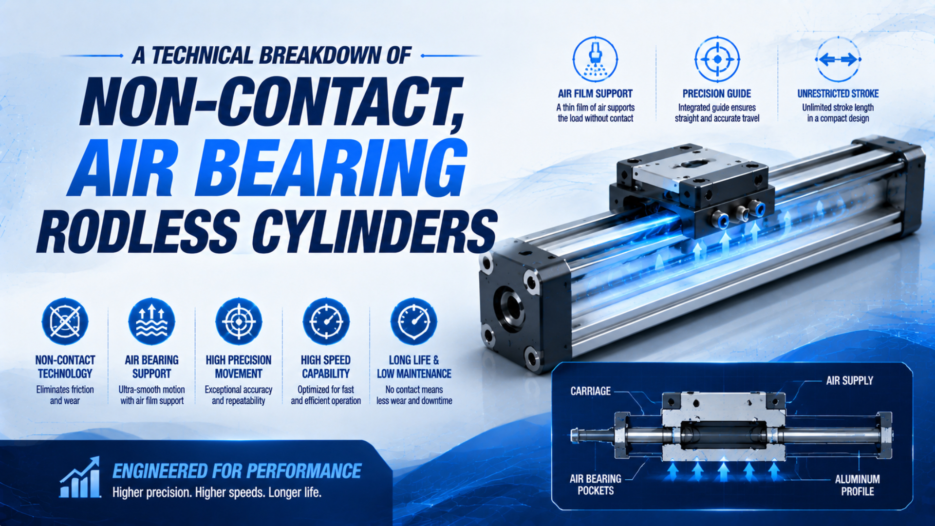
An air bearing rodless cylinder is most accurately treated as an air-bearing-guided rodless linear axis. The rodless layout describes where the moving carriage sits. The air bearing describes how that carriage is guided. A linear motor, voice coil, pneumatic piston, or another actuator may provide the thrust, while an encoder and controller determine positioning performance.
That distinction matters. PI’s A-142 stage combines an air-preloaded guide with a voice-coil drive and linear encoder, while SMC’s CY3B is a magnetically coupled pneumatic cylinder that requires an external guide for its load (PI, 2026; SMC, retrieved 2026). They are not interchangeable product classes.
Key Takeaways
- “Rodless” describes the motion package; “air bearing” describes the guide interface.
- PI’s A-142 separates a voice-coil drive, air bearing, and 5 nm encoder.
- Load, stiffness, drive force, accuracy, air flow, and loss-of-pressure protection need separate checks.
- Catalogue values are model-specific, not universal air-bearing limits.
What Is a Non-Contact Air Bearing Rodless Cylinder?
SMC offers the CY family in nine bore sizes from 6 to 63 mm and standard strokes up to 1,000 mm, yet its CY3B page says the load must use an external guide. That specification shows why “rodless cylinder” alone does not identify the guide technology (SMC, retrieved 2026).
A conventional rodless pneumatic cylinder converts chamber pressure into linear thrust. The piston may be mechanically coupled through a sealed slot or magnetically coupled through the tube wall. Its carriage still needs a way to react radial loads and pitch, yaw, and roll moments. Some products integrate rolling or sliding guides; basic cylinders depend on a separate machine guide.
An air-bearing rodless axis replaces that contacting guide interface with an externally pressurized gas film. “Non-contact” applies to the designed bearing surfaces while adequate pressure and the specified gap are maintained. It does not prove that every item in the machine is contact-free. Cable carriers, end stops, counterbalances, seals, and process tooling may still contain contacting parts.
The term also does not tell you what creates thrust. The PI A-142 uses a voice coil. Aerotech’s FiberGlide 3D uses a brushless linear servomotor. A custom system could pair an air guide with a pneumatic drive, but the piston seals and control valve would remain pneumatic components. For background on conventional layouts, compare the magnetically coupled rodless cylinder guide with the rodless air slide guide.
The cleanest specification language is “air-bearing-guided rodless linear axis,” followed by separate drive, feedback, and safety descriptions. That wording prevents a purchasing team from assuming that a familiar pneumatic cylinder catalogue page guarantees air-bearing accuracy, cleanliness, or load capacity.
How Does the Air Film Carry and Control a Load?
PI specifies 445 to 515 kPa operating pressure and up to 28 L/min air consumption for its A-142, with a maximum permissible Z push force of 30 N at the stated bearing pressure. Those linked values show that pressure, flow, load, and film geometry must be evaluated together (PI, 2026).
An aerostatic bearing feeds compressed air through orifices, grooves, slots, or porous media before relative motion begins. The restrictor and the small bearing gap create a pressure distribution over the projected area. The useful support force is the pressure above ambient integrated across that area:
Here, is supported load in newtons, is local absolute film pressure in pascals, is ambient absolute pressure, and is the effective bearing area in square metres. This relationship is conceptual unless the actual pressure distribution is known. Multiplying supply pressure by the full pad area usually overstates usable load.
The word aerostatic is important. Hydrodynamic or aerodynamic bearings generate supporting pressure from relative surface motion and converging geometry. A precision linear stage that must float while stationary normally relies on an external pressure source. Bernoulli’s equation alone is not a sizing method for its load or stability.
Orifice and porous-media compensation behave differently as the gap changes. New Way describes porous media as distributing air through many small passages, while its technical comparison notes that orifice bearings can become unstable or lose stiffness when the gap is starved (New Way technical report, retrieved 2026). Use the maker’s load-versus-gap, stiffness, and flow curves for the chosen bearing.
Preload gives the guide bidirectional control. Designers may use opposed bearings, gravity, magnets, flexures, or vacuum. A vacuum-preloaded bearing uses negative pressure to oppose the positive bearing force, allowing one guide surface to control fly height and stiffness (New Way, retrieved 2026). The preload consumes part of the bearing’s available load margin.
Drive, Guide, Feedback, and Safety Are Separate Functions
The PI A-142 combines four traceable functions: a 5 N typical drive force in each direction, an air-preloaded guide, a 5 nm encoder resolution, and a recommendation to connect an air-pressure sensor to the controller E-stop. None of those values can substitute for another (PI, 2026).
The separation changes how specifications should be read:
- Drive force determines acceleration, disturbance rejection, and process-force capacity along the travel axis.
- Bearing load and moment ratings determine whether the carriage remains within its permitted air gap.
- Encoder and calibration determine what the controller can measure and correct.
- Mechanical geometry determines straightness, flatness, pitch, yaw, and Abbe error at the point of interest.
- Air system and interlocks determine whether the bearing can remain safely separated during operation and shutdown.
Sensor resolution is not positioning accuracy. PI lists 5 nm sensor resolution for the A-142 but calibrated positioning accuracy of ±0.2 µm and bidirectional repeatability of 0.1 µm. Its notes also tie calibrated accuracy to controller-driven compensation and warn that thermal drift is not included. The position-sensing guide explains why feedback technology and end result must be stated separately.
How Do Load, Moment, Stiffness, and Drive Force Interact?
New Way lists its 50 mm vacuum-preloaded bearing at a 45 N ideal load, 13 N/µm stiffness, 0.97 NL/min flow, and 73 N maximum hold-down force at 50.7 kPa vacuum. One product row contains four different limits because no single “load capacity” number describes the complete axis (New Way, retrieved 2026).
Start with all six load components at the carriage: three forces and three moments. Payload mass alone is not enough. A tool offset converts process force into a moment, and acceleration adds inertial force. For the motion direction:
is required actuator force in newtons, is moved mass in kilograms, is target acceleration in metres per second squared, is useful process resistance, covers cable or hose forces, and covers stated uncertainty. The bearing’s low guide friction does not remove these forces.
Static stiffness describes how much the guide deflects when load changes near an operating point:
Here, is vertical stiffness in newtons per metre or newtons per micrometre, is supported load, and is air-film thickness. The negative sign reflects the usual convention that increasing load reduces the gap. Use the maker’s curve because restrictor design, supply pressure, preload, surface geometry, and gap all shape the derivative.
What happens during a fast scan? Dynamic stiffness, structural modes, servo bandwidth, squeeze-film damping, and service-loop forces can matter more than the static number. A static lift curve cannot guarantee settling time.
| Specification | What it answers | What it does not answer |
|---|---|---|
| Ideal or nominal load | Intended steady operating point | Shock survival or moment capacity |
| Maximum load | Stated limit under defined conditions | Precision at that limit |
| Static stiffness | Small deflection for a load change | Dynamic resonance or servo settling |
| Drive force | Available thrust along motion | Bearing load and moment capacity |
| Encoder resolution | Smallest feedback increment | System accuracy or repeatability |
| Accuracy and repeatability | Model-specific positioning results | Performance after different mounting or thermal conditions |
In our experience, the most useful RFQ sketch shows the payload centre of gravity, process-force point, travel, orientation, acceleration profile, and cable exit. A mass and stroke alone hide the two details that often control the design: overturning moment and service-loop force.
What Air Quality and Loss-of-Pressure Protection Are Required?
Aerotech specifies 80 psi ±5 psi, 53.1 SL/min maximum air consumption for a three-axis FiberGlide system, 0°F pressure dew point, and filtration to 0.25 µm or better. It also requires an in-line pressure switch tied to the controller E-stop (Aerotech FiberGlide 3D, retrieved 2026).
Those are FiberGlide requirements, not universal targets. PI’s A-142 instead lists 445 to 515 kPa pressure, 28 L/min maximum flow, filtration to 1.0 µm or better, oil-free air, and a -15°C dew point. New Way commonly refers to clean, dry air at 60 psi for its products. The correct air-preparation package comes from the selected bearing or stage manual.
Specify the utility chain from the plant header to the bearing:
- Available pressure and flow during simultaneous machine demand
- Filter rating and element condition monitoring
- Oil and aerosol requirement
- Pressure dew point at the relevant operating pressure
- Local regulator, gauge, pressure switch, and flow indication
- Hose ID, length, bend radius, and pressure loss
- Startup, normal stop, E-stop, and air-loss sequence
Air loss is a mechanical event. If pressure falls below the maker’s threshold, the carriage can touch the guide while the drive is still producing force. The control system should remove or control thrust before damaging motion occurs. Depending on orientation and risk assessment, the design may also need a brake, counterbalance, landing surface, retained air volume, or controlled park position. Those features must be engineered; they are not implied by the words “air bearing.”
New Way’s care instructions say not to operate its products without air pressure and call for clean, dry air free of moisture and contaminants (New Way, retrieved 2026). For plant-level contaminant definitions, use the ISO 8573-1 compressed-air quality guide, then apply the tighter product requirement where necessary.
Where Does an Air-Bearing Rodless Axis Fit Best?
Published air-stage specifications span very different machines: PI’s A-142 has 10 mm travel and 30 N Z-load capacity, while Aerotech’s dual-carriage IGM has 1 m travel and 50 kg capacity per carriage. That range is evidence for model-specific selection, not a universal air-bearing performance claim (PI, 2026; Aerotech, retrieved 2026).
Air-bearing axes make sense when smooth low-disturbance motion, geometric accuracy, high duty cycle, or lubricant-free guiding is worth the added utility and integration work. Typical candidates include optical scanning, surface metrology, photonics alignment, semiconductor inspection, and precision laser processing. The application still needs an evidence-based contamination review.
New Way reports one vacuum-preloaded bearing test as satisfying ISO Class 3 particle limits, and Aerotech states FiberGlide can meet a cleanroom class with proper integration. Those are product and system claims under stated test or integration conditions. They do not prove “zero particles” for every air-bearing machine, especially when cables, motors, brakes, process tooling, and incoming air remain part of the system.
| Design question | Conventional pneumatic rodless cylinder | Air-bearing-guided rodless axis |
|---|---|---|
| Primary reason to choose | Compact long-stroke force and transfer | Smooth precision motion and guide geometry |
| Typical drive | Pneumatic piston | Linear motor, voice coil, or custom drive |
| Guide contact | External or integrated contact guide | Designed non-contact air film in normal operation |
| Positioning | End switches or added feedback/control | Usually encoder-based closed-loop control |
| Utility dependency | Compressed air for thrust | Conditioned air for bearing plus drive power or drive air |
| Air-loss concern | Loss of force or uncontrolled load motion | Bearing touchdown plus drive and load hazards |
| Selection basis | Bore, pressure, stroke, speed, guide load | Six-axis load, stiffness, geometry, drive, feedback, air, safety |
A standard rodless cylinder is usually the better answer for simple transfer, clamping, pushing, and long-stroke motion that does not need precision guide geometry. Explore the available rodless pneumatic cylinder types before adding air-bearing complexity. For a clean environment, compare the whole machine against the cleanroom pneumatic component selection guide.
The strongest business case is rarely “less friction” by itself. It is the value of a measurable process result, such as scan uniformity, straightness, settling time, non-contact guiding, or reduced guide maintenance, minus the cost of conditioned air, controls, precision mounting, and safe touchdown management.
Selection and Commissioning Workflow
Aerotech states ±1 µm calibrated accuracy and ±0.6 µm repeatability for its 1 m IGM, while its mounting and motion specifications remain part of the same product definition. Commissioning should therefore prove the installed axis against the application requirement, not merely confirm that the carriage moves (Aerotech IGM, retrieved 2026).
Use this acceptance sequence:
- Verify the mounting surface, fastener sequence, carriage orientation, and allowed thermal expansion.
- Measure pressure at the stage during the worst simultaneous demand, not only at the regulator while idle.
- Confirm filter, dryer, and pressure-switch settings against the selected manual.
- Float the bearing before enabling motion, following the maker’s startup sequence.
- Check free travel and service-loop force at both ends and mid-stroke.
- Tune the servo with the real payload, then measure accuracy, repeatability, straightness, and settling at the process point.
- Test the documented air-loss response at a safe condition. Confirm that drive energy, gravity, and process loads are controlled.
- Record baseline flow, pressure, noise, temperature, and error maps for future maintenance comparison.
Don’t accept a sub-micron claim without a test definition. State travel, payload, orientation, mounting surface, temperature range, controller, compensation state, measurement instrument, sampling method, and whether the value is accuracy, repeatability, resolution, or minimum incremental motion. Those labels are not synonyms.
Air Bearing Rodless Cylinder FAQs
Aerotech’s FiberGlide sheet specifies 80 psi ±5 psi and a pressure-switch E-stop connection, while PI’s A-142 uses a different 445 to 515 kPa range. These FAQs keep terminology, performance, and air preparation tied to the selected stage instead of turning one catalogue value into a universal rule (Aerotech, retrieved 2026; PI, 2026).
Is an air bearing rodless cylinder always pneumatically driven?
No. The air supply may support only the guide. PI’s A-142 uses a voice-coil motor, and Aerotech FiberGlide uses a brushless linear servomotor. A custom axis could use pneumatic thrust, but the drive, bearing, encoder, and safety system still need separate specifications. “Air bearing” does not identify the actuator technology.
Does non-contact motion mean zero friction and zero particle generation?
No universal zero claim is defensible. The intended bearing faces avoid solid contact while the specified air film exists, but viscous drag, cables, hoses, motors, brakes, stops, and process tooling remain. Cleanroom suitability must be supported by a product or system test and by proper integration, air quality, cleaning, and maintenance.
Can encoder resolution be used as positioning accuracy?
No. PI lists 5 nm encoder resolution for the A-142, yet its calibrated positioning accuracy is ±0.2 µm and its bidirectional repeatability is 0.1 µm. Mounting geometry, calibration, thermal drift, servo behaviour, measurement uncertainty, and payload affect the installed result. Specify and verify each metric separately.
What happens when the bearing air supply fails?
The air film can collapse and the carriage may touch its guide. Aerotech requires an in-line pressure switch tied to controller E-stop for FiberGlide, and New Way warns against operation without air pressure. The machine design must also control drive force, gravity, payload motion, and any process hazard during the pressure-loss sequence.
When should a conventional rodless cylinder be selected instead?
Choose a conventional pneumatic rodless cylinder when compact long-stroke transfer, force, speed, and straightforward control matter more than precision guide geometry or non-contact guiding. Its bore, pressure, coupling, guide, moments, cushioning, and switches still require selection. Air bearings add value only when the process result justifies conditioned air and precision integration.
Sources and technical references
- SMC, CY3B Magnetically Coupled Rodless Cylinder, Basic Type, retrieved July 19, 2026.
- SMC, CY3B Replacement Parts and Seal Kit, retrieved July 19, 2026.
- PI, A-142 PIglide Voice-Coil Linear Stage with Air Bearings, datasheet dated March 16, 2026.
- Aerotech, FiberGlide 3D Series, retrieved July 19, 2026.
- Aerotech, Dual-Carriage Air-Bearing IGM System, retrieved July 19, 2026.
- New Way, Orifice vs. Porous Media Air Bearings, retrieved July 19, 2026.
- New Way, Vacuum Preloaded Air Bearings, retrieved July 19, 2026.
- New Way, Care and Air, retrieved July 19, 2026.