

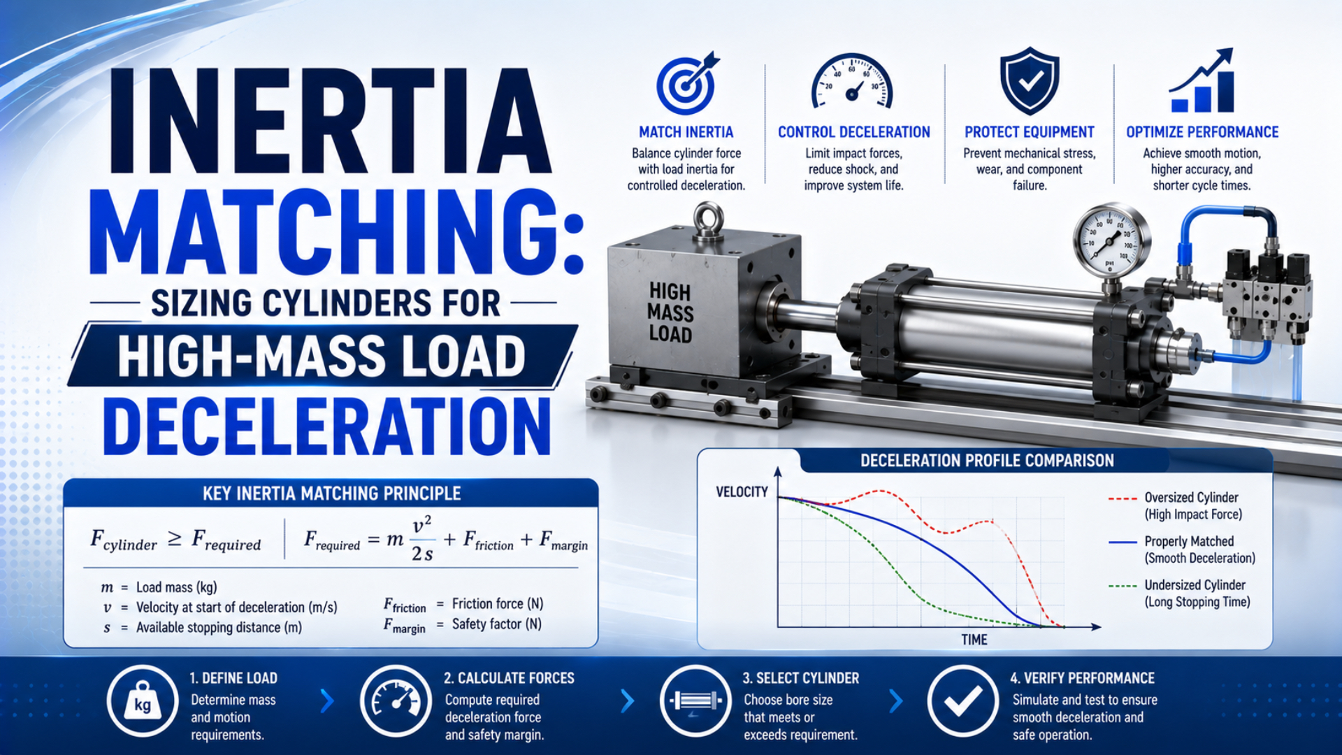
Inertia matching for pneumatic cylinders means matching the actual moving mass and stopping-energy demand to the cylinder, guide, cushion, shock absorber, and stop structure as one system. It is not the motor-to-load inertia ratio used in servo sizing. A cylinder can produce enough thrust to move a load yet remain unable to stop it safely.
Reliable selection separates motion force from deceleration capacity. Calculate the total energy entering the stop, check both energy per event and sustained duty, then compare the result with the exact manufacturer’s mass-speed envelope or allowable-energy data. Commissioning measurements must confirm the assumptions before production release.
Key Takeaways
- Parker states that cushion-entry speed is typically about 50% higher than average cylinder speed.
- Calculate kinetic energy plus work added during deceleration, not kinetic energy alone.
- Treat the calculated force as an average, never an unverified peak.
- Accept a design only against exact catalog limits and measured machine behavior.
What Does Inertia Matching for Pneumatic Cylinders Mean?
Parker states that piston speed at cushion entry is typically about 50% higher than average speed, which shows why nominal stroke time cannot define a high-mass stop. Pneumatic inertia matching is therefore a system check connecting moving mass, entry speed, propelling force, stopping distance, cycle rate, and the selected device’s published limits (Parker OSP-P catalog, retrieved 2026).
Servo engineers use inertia matching to compare reflected load inertia with motor inertia for control stability and acceleration performance. By contrast, a pneumatic cylinder has no equivalent universal ratio because its compressed-air chambers, valve flow, exhaust restriction, friction, load orientation, structure, and end-of-stroke device all affect how the load slows. For this guide, moving mass is every translating component that reaches the stop with the load. For example, it can include the payload, carriage, tooling, brackets, moving cable chain, cylinder piston assembly, and an external guide carriage; use measured or drawing-derived masses rather than a generic percentage added to the payload.
Cushion-entry speed is the piston or carriage speed when the built-in cushion begins restricting exhaust. Put differently, it is not necessarily the full-stroke average. That distinction matters because kinetic energy changes with the square of speed. If the actual entry speed is 50% higher, the kinetic energy is 2.25 times the value calculated from average speed.
Meaningful matching creates an evidence chain, not a single sizing factor:
| Design question | Required evidence | Failure if omitted |
|---|---|---|
| Can the actuator move and accelerate the load? | Pressure, effective piston area, friction, orientation, valve flow | Slow, stalled, or unstable motion |
| Can the stopping device absorb one event? | Total event energy and exact per-event rating or mass-speed envelope | Bottoming, impact, structural shock |
| Can it repeat at production rate? | Events per hour, thermal rating, return time, temperature | Heat accumulation and changing response |
| Can the machine carry the reaction load? | Stop path, guide moments, bracket stiffness, fastener and frame checks | Misalignment, loosened mounts, guide damage |
This system view also prevents an incorrect bore-only conclusion. Bore changes available thrust and air demand, but built-in cushion capacity is product-specific. Therefore, two cylinders with the same bore can have different cushion geometry, effective cushion length, permissible speed, and allowable energy.
How Do You Separate Thrust Sizing From Deceleration Capacity?
SMC selection guidance checks operating pressure, piston speed, load weight, moment, kinetic energy, and cushion type against allowable ranges. Those are separate constraints, not interchangeable outputs. First choose a cylinder and valve circuit that can produce the required motion; then verify that its guide and stopping system can tolerate the resulting load and speed (SMC selection guide, retrieved 2026).
Cylinder thrust is the pressure-derived force available at the piston after accounting for the active area and opposing effects. It answers whether the axis can accelerate, overcome friction, resist process forces, and maintain the required motion; the pneumatic cylinder force guide explains the bore-area calculation and its limits.
Stopping capacity answers a different question: where does the moving system’s energy go, over what distance, at what repetition rate, and through which physical load path? In particular, a larger bore may increase thrust into the cushion region. If the active chamber continues driving during deceleration, that extra work can increase rather than reduce the stopping demand.
Do not select bore by dividing an energy-derived average force by supply pressure. That operation mixes a stopping result with a motion-force input and ignores the cushion’s specific construction. Instead, use a defensible sequence:
| Stage | Decision output |
|---|---|
| Define motion | Worst credible load, orientation, acceleration, working speed, and required cycle time |
| Size the drive | Effective piston area and valve flow with documented pressure and friction assumptions |
| Check the guide | Load-center offsets and permissible moments throughout travel |
| Calculate each stop | Separate extension and retraction energy because their conditions can differ |
| Screen hardware | Exact cylinder cushion, absorber, stop, and structure against published limits |
| Accept the machine | Measured evidence plus the released adjustment settings |
A rodless cylinder may solve a space or stroke constraint, but it is not automatically more tolerant of a high-energy stop. Specifically, its carriage, guide option, moments, load center, speed, cushion, and mounting structure still require model-specific checks; for long-stroke layouts, use the rodless cylinder load-capacity guide to separate guide capacity from stopping capacity.
How Do You Build the Complete Stopping-Energy Budget?
ACE bases industrial shock absorber selection on five application inputs: moving mass, impact velocity, drive force, cycles per hour, and the number of absorbers operating in parallel. This discipline improves cylinder cushion screening because it distinguishes one-stop energy from continuing drive work and repeated thermal duty (ACE Controls calculation basis, retrieved 2026).
For example, start with the kinetic energy of all translating mass at the beginning of the usable deceleration region:
is kinetic energy in joules, is total moving mass in kilograms, and is cushion-entry speed in metres per second. This equation assumes translating motion. A mechanism with rotating components may require their reflected rotational energy as an additional term.
Next calculate the work added by the net propelling force over the usable stopping distance:
is drive work in joules, is the net force in newtons that continues pushing in the direction of travel, and is usable deceleration distance in metres. In particular, include gravity in with the correct sign for a vertical axis. Do not add gravitational work twice.
Total stopping-system energy for one event is:
is energy per stop in joules. However, if a measured net force varies strongly over the deceleration distance, replace the constant-force product with the area under the force-distance curve. The simple equation is valid only when the stated constant or conservative average is defensible.
An ideal average resisting force follows from energy divided by distance:
is an average over the full usable distance. In fact, it is not peak force. Real pressure rise, cushion needle setting, seal friction, structural compliance, contact stiffness, and remaining velocity can produce a much higher instantaneous load. The end-of-stroke force guide covers that distinction in more detail.
Repeated operation needs a separate duty calculation:
is energy per hour in joules per hour, and is the number of stopping events per hour at that end. Therefore, use the highest sustained production rate, including retry cycles or closely spaced batches. A device may pass one event yet fail its hourly or return-time limit.
Which Speed and Mass Belong in the Calculation?
Parker instructs designers to use speed at the start of cushioning and to include the mass of the moving carriage, adding that entry speed is typically about 50% above average. The required inputs are therefore the total mass and local entry speed at the actual stop, not payload nameplate mass and full-stroke distance divided by cycle time (Parker OSP-P catalog, retrieved 2026).
Build the mass inventory from the machine rather than using a universal uplift. For example, a tooling plate may be negligible on one axis and larger than the payload on another, while a moving hose pack or gripper can change mass between product variants; record the basis for each item so future tooling changes trigger a new check.
| Include when it reaches the stop | Do not include without a kinematic reason |
|---|---|
| Payload and product carrier | Stationary cylinder barrel or fixed frame |
| Moving carriage, piston assembly, and guide block | Remote valve manifold |
| Tooling, gripper, brackets, and moving sensors | Fixed guarding |
| Moving cable chain, hose support, or coupled slide | Counterweight that moves independently |
| Reflected rotating energy from a linked mechanism | The whole machine mass |
Measure velocity as close as practical to the start of the deceleration zone. For instance, position data from a suitable sensor can provide local velocity after filtering, while a high-speed trace may reveal bounce or a late acceleration that the controller’s average cycle value hides. Use the speed at the loaded operating condition and check both stroke directions; the piston-velocity guide explains why valve flow and local pressure can make a simple average misleading. Pressure deserves the same treatment because supply pressure at the regulator is not necessarily pressure at the cylinder port during a fast move. Record both chamber pressures through the stopping event when possible; this evidence helps estimate net propelling force and distinguishes inadequate valve flow from an incorrectly adjusted cushion.
In our experience, a synchronized trace of position and both cylinder-port pressures is usually more useful than a louder end-stop observation. It shows when cushioning begins, whether velocity is still rising, how rapidly back pressure builds, and whether the drive chamber continues adding work.
Worked Example: An 800 kg Load Entering the Cushion
ACE requires mass, impact speed, continuing drive force, cycles per hour, and absorber count before a shock absorber can be screened. However, this hypothetical example uses all five ideas only to expose the stopping demand. It deliberately stops short of choosing a cylinder model. Catalog data and machine tests remain mandatory (ACE Controls calculation basis, retrieved 2026).
Assume an axis has the following worst-case operating point:
| Input | Example value | Basis |
|---|---|---|
| Total moving mass, | 800 kg | Payload, carriage, tooling, and moving hardware |
| Cushion-entry speed, | 0.8 m/s | Measured at the start of deceleration |
| Net continuing drive force, | 1,200 N | Conservative force in direction of travel |
| Usable stopping distance, | 0.020 m | Confirmed for the candidate device |
| Stopping events at this end, | 600 per hour | Highest sustained production rate |
The translating kinetic energy is:
The force that remains active adds:
Total energy per stopping event is therefore:
An ideal average resisting force over the full stopping distance is:
That 14,000 N value must not be labeled peak cushion force. In other words, it only shows the mean resistance required if the full 20 mm is used; bottoming before the end, a steep pressure rise, mechanical contact, or structural compliance can create a different peak load.
At 600 stopping events per hour, the sustained energy throughput is:
If an external shock absorber is considered and contact occurs at the same speed, ACE’s effective-mass quantity can be expressed as:
is effective mass in kilograms and is impact speed at the absorber in metres per second. For this example:
That result does not authorize a model selection. Accordingly, the candidate must still pass its exact per-event energy, hourly capacity, effective-mass range, impact-speed range, usable stroke, return time, temperature, adjustment, mounting, and stop requirements. The dedicated external shock absorber sizing guide explains those checks.
How Do You Compare the Result With a Built-In Cushion?
SMC data for one CJ2 family illustrates why exact model data matters: the published absorbable energy for air cushioning is 0.07 J at 10 mm bore and 0.18 J at 16 mm bore, with a listed effective cushion length of 9.4 mm for both. Those numbers describe that series, not all pneumatic cylinders (SMC model selection data, retrieved 2026).
Begin with the manufacturer’s selection method for the exact series, bore, stroke, guide option, and cushion type. For example, some catalogs publish an allowable kinetic-energy value. Others use a moving-mass versus cushion-entry-speed graph. A graph can contain limits that a single joule rating does not reveal, so follow the stated method rather than converting everything into one generic threshold.
For a built-in pneumatic cushion, check these items at the same operating point:
| Check | Acceptance question |
|---|---|
| Moving mass and entry speed | Does the point fall inside the exact series envelope for the selected bore and cushion? |
| Energy per event | Is total required energy compatible with the manufacturer’s definition and published limit? |
| Direction | Do extension and retraction both pass with their own mass, force, and speed conditions? |
| Cushion setting | Can the needle be adjusted without bottoming, bounce, or excessive time loss? |
| Pressure and exhaust path | Are supply pressure, back pressure, valve capacity, tubing, and silencers within the stated conditions? |
| Guide and moments | Do load-center offsets and deceleration reactions remain within every guide limit? |
| Structure | Can brackets, fasteners, frame, and any positive stop carry the reaction load? |
Festo describes three common cushioning approaches: mechanical or elastic cushioning, pneumatic or servo-pneumatic cushioning, and hydraulic cushioning. Therefore, the needle position is part of commissioning rather than a universal factory value because adjustable pneumatic cushioning depends on mass, entry speed, deceleration, pressure, and flow resistance (Festo cushioning overview, retrieved 2026). Open the needle from a controlled initial setting and approach production speed under the manufacturer’s procedure. For example, closing it too far can trap pressure abruptly and cause bounce or a hard pressure spike; in contrast, opening it too far can leave excessive residual speed at the end cap. The goal is controlled deceleration without end contact, rebound, or unacceptable cycle-time variation. The cylinder cushioning guide describes the exhaust-restriction process inside a pneumatic cushion.
When Should You Use an External Shock Absorber or Stop?
Festo groups cylinder deceleration into three methods, while Parker directs users to add shock absorbers when the rodless cylinder’s permissible mass-speed cushioning range is exceeded. An external absorber is therefore a valid design choice, not proof that the actuator bore is wrong; the decision depends on energy, repetition, precision, structure, and the required load path (Festo; Parker, retrieved 2026).
Use the built-in cushion when the exact manufacturer’s method accepts the mass-speed point and the commissioned stop remains controlled across load, pressure, temperature, and production-rate variation. That said, this solution keeps the stopping function inside the cylinder while the machine structure still carries the reaction through its mounts. Consider an external industrial shock absorber when energy per event or hourly duty exceeds the built-in cushion, when a longer controlled stopping distance is useful, or when the reaction should enter a dedicated stop bracket. In addition, the contact geometry must remain axial, the mounting must resist the load, and any required positive stop must prevent the absorber from bottoming mechanically.
Choose an external mechanical stop or redesign when the final position must be defined by a rigid machine datum, when safety or process forces cannot rely on compressed air, or when no available cushion or absorber passes all limits. Alternatively, reduce entry speed, lengthen the deceleration distance, lower moving mass, change the motion profile, relocate the stop, or split the motion into stages.
Reducing speed is unusually powerful because the kinetic portion changes with its square. Dropping cushion-entry speed from 0.8 m/s to 0.6 m/s cuts kinetic energy by 43.75% at unchanged mass; consequently, the full event-energy calculation must still be repeated because this change does not automatically reduce continuing drive work.
Commissioning and Acceptance Checks
Parker’s 50% entry-speed guidance means a design based on average travel speed can begin commissioning with a 2.25-fold kinetic-energy error. Acceptance testing must therefore capture local speed at cushion entry, not merely completed stroke time; test the highest permitted mass, speed, pressure, cycle rate, and relevant temperature under controlled conditions (Parker OSP-P catalog, retrieved 2026).
Define acceptance criteria before adjusting the machine. Specifically, the criteria should include permissible final speed or no end-cap contact, no sustained rebound, pressure within component limits, guide and stop loads within published ratings, stable cycle time, and temperatures within the selected device’s range. Add noise or vibration thresholds only when the measurement method is repeatable.
A release test should cover three distinct states:
- Cold start.
- The heaviest allowed load at the highest released entry speed.
- Sustained production-rate cycling long enough to expose heat accumulation, response drift, rebound, loose hardware, bracket movement, or return-time problems.
A practical release record contains:
| Evidence | What it confirms |
|---|---|
| Configuration and part numbers | The tested cylinder, cushion, guide, valve, silencer, absorber, and stop match the released design |
| Mass and load-center record | The test represents the heaviest permitted tooling and product geometry |
| Position and velocity trace | Entry speed, stopping distance, residual motion, and rebound are visible |
| Both cylinder-port pressures | Drive work and cushion back pressure can be assessed |
| Cycle-rate and temperature log | Sustained operation does not hide a thermal limit |
| Fastener, bracket, and guide inspection | Reaction loads are not loosening or distorting the load path |
| Final adjustment settings | Cushion needles, regulators, flow controls, and controller values can be restored |
Run separate tests for extension and retraction. Repeat them after the machine reaches a representative thermal condition, then inspect mounts, carriage play, stop faces, seals, and fasteners. A brief single-cycle demonstration cannot prove hourly capacity or stable behavior. Treat any product, tooling, speed, pressure, valve, tubing, silencer, cushion setting, or software motion-profile change as a reason to review the calculation. As a result, a change that appears upstream can alter cushion-entry velocity or continuing drive force; keep the accepted operating envelope with the machine documentation rather than only the nominal cylinder part number.
Inertia Matching FAQs
ACE begins shock absorber selection with five application inputs, while SMC and Parker add product-specific kinetic-energy, mass-speed, guide, and cushion checks. These frequently asked questions address the shortcuts most likely to break that evidence chain: bore-only selection, average speed, kinetic-energy-only calculations, incorrect assumptions about external absorbers, and reliance on flow controls as stops.
Does a larger bore always improve deceleration capacity?
No. A larger bore increases available pneumatic thrust at the same pressure, but cushion capacity is specific to the exact cylinder series, bore, and cushion design. More thrust can also add drive work during deceleration. Recalculate the motion and stop, then check the manufacturer’s mass-speed envelope or allowable-energy data.
Should average cylinder speed be used for cushion sizing?
Not when cushion-entry speed is available. Parker states that entry speed is typically about 50% above average, which would make kinetic energy 2.25 times higher at unchanged mass. Measure local speed near the start of cushioning or apply the exact manufacturer’s prescribed method when measurement is not yet possible.
Is kinetic energy alone enough to size the stop?
No. Add the work of cylinder thrust, gravity, springs, or other forces that keep driving the load through the stopping distance. Then check both energy per event and events per hour. Kinetic energy alone can understate demand even when the mass and impact-speed values are accurate.
Does using an external shock absorber mean the cylinder is undersized?
No. An external absorber can be the correct system choice when the built-in cushion’s mass-speed envelope, event capacity, hourly duty, or load path is unsuitable. The cylinder can still be correctly sized for motion. Verify absorber energy, speed, effective mass, stroke, return time, alignment, mounting, and stop requirements.
Can a flow control valve replace a cushion or shock absorber?
No. A flow control can influence cylinder speed before the stop, but it does not by itself provide a rated end-of-stroke energy absorber or positive mechanical load path. Use it to shape the motion only within a validated circuit, then verify the selected cushion, absorber, or stop at worst-case conditions.
Sources and Technical References
Parker: OSP-P rodless cylinder catalog, cushion-selection inputs, moving-mass definition, entry-speed guidance, and the rule for adding shock absorbers. Retrieved July 23, 2026.
ACE Controls: Calculation bases for industrial shock absorbers, kinetic energy, drive work, total event energy, hourly duty, and effective mass. Retrieved July 23, 2026.
SMC: Model selection data, product-specific allowable kinetic energy and effective cushion length. The guide selection software screens pressure, speed, load, moment, kinetic energy, and cushion choice. Retrieved July 23, 2026.
Festo: Cylinder cushioning overview, mechanical, pneumatic, and hydraulic cushioning methods. Retrieved July 23, 2026.
NIST: Guide to the SI, unit symbols and expression conventions. Retrieved July 23, 2026.