

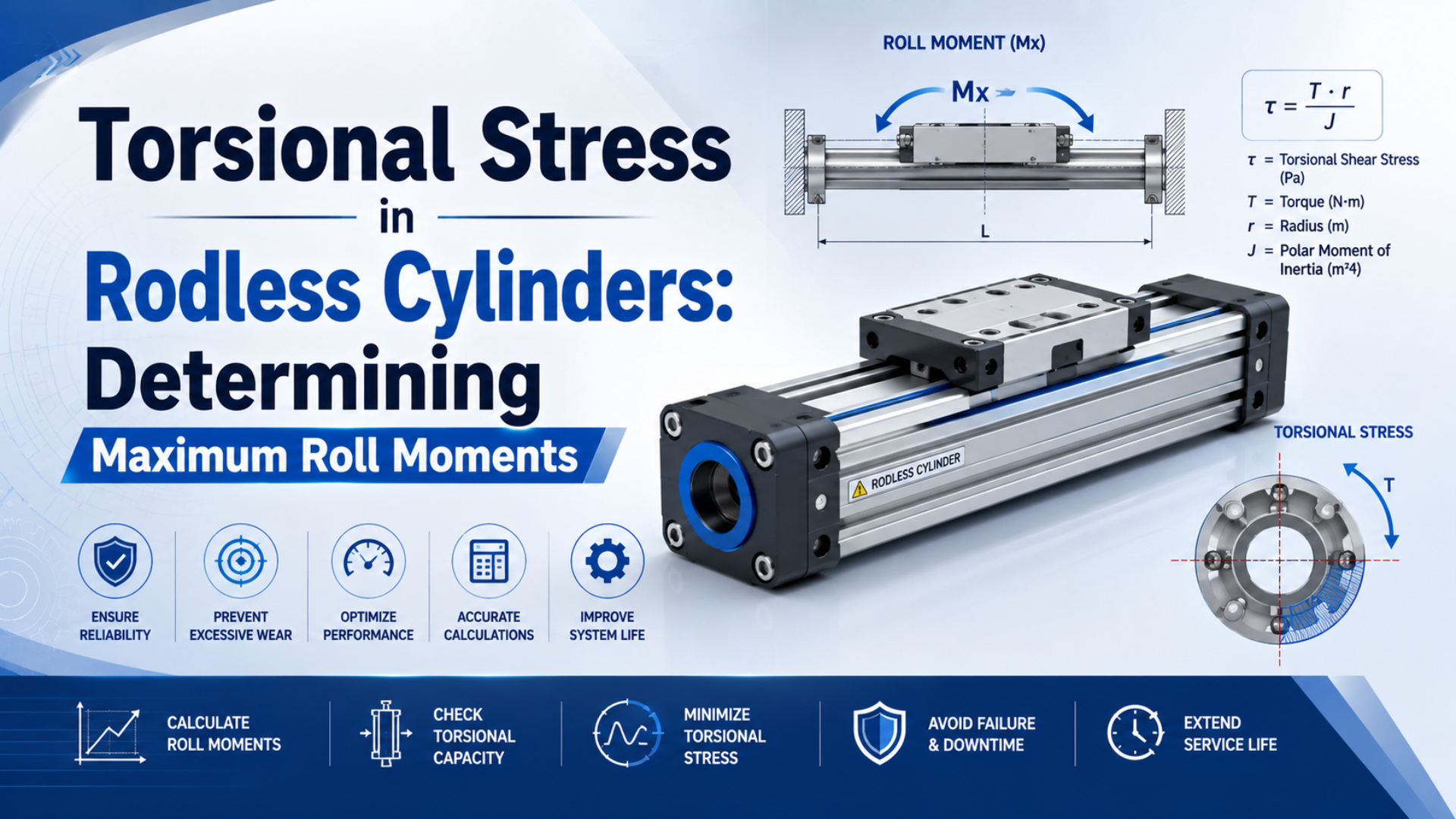
Rodless-cylinder roll moment is the external torque acting about the actuator’s longitudinal travel axis. Calculate the applied moment from every force and its perpendicular offset, include acceleration and direct tool torque, then compare the result with the exact model’s published limit and combined-load rule.
That process determines whether a carriage-guide system is suitable. In contrast, it does not calculate the internal shear stress in a rail, bearing, carriage, tube, or fastener. Those stresses depend on proprietary geometry and material details, so the manufacturer’s permissible moment data remains the selection boundary.
Key Takeaways
- Parker lists 1.5 N·m maximum for a standard OSP-P25 but 260 N·m for its HD25 guide.
- Calculate roll moment about the catalog’s stated axis, including dynamic and process forces.
- Check simultaneous forces and moments through the exact manufacturer’s interaction rule.
- Never infer guide capacity from bore alone.
What Is a Rodless Cylinder Roll Moment, and Is It Torsional Stress?
Parker’s current OSP-P catalog evaluates three moment axes, , , and , plus transverse forces and . Roll moment is the external moment about the travel axis. Torsional stress is the internal material response, which cannot be recovered from without the component’s geometry, material, and load path (Parker OSP-P catalog, retrieved 2026).
Roll moment is the applied moment that tries to rotate the payload and carriage around the cylinder’s longitudinal axis. Specifically, if the catalog calls that axis , the roll moment is ; a vertical force on a payload whose center of mass sits laterally away from the actuator creates this load. Torsional stress is an internal shear-stress distribution within a specific member. A solid shaft, hollow tube, rail, carriage, fastener group, and bearing set respond differently to the same torque. Therefore, the familiar shaft equation isn’t a valid substitute for a rodless-cylinder catalog rating. Engineers can calculate applied roll moment from machine geometry, but only the manufacturer can publish carriage-guide capacity after accounting for bearing spacing, contact geometry, rail stiffness, attachment details, speed limits, and validation method.
Drive coupling is another separate boundary. For example, a mechanical band transmits axial piston force through a slot, while a magnetic system transmits force through the tube wall. Neither coupling force automatically proves that the external carriage can support roll moment. The rodless cylinder load-mechanism guide separates drive, guidance, cushioning, and structure in more detail.
How Do You Calculate the Applied Roll Moment?
Parker expresses a moment as force multiplied by perpendicular distance and measures offsets from the actuator center. For roll about the axis, the complete three-dimensional relation uses the and force components and offsets; add any direct process torque about before comparing the magnitude with the published rating (Parker OSP-P catalog, retrieved 2026).
Start with a free-body diagram. In particular, mark the catalog’s , , and axes, the center of the carriage or guide reference point, the payload center of mass, and every process-force application point. A moment arm is the perpendicular distance from the reference axis to the force line of action, not simply the longest visible bracket dimension.
The signed roll moment about the axis is:
is roll moment in newton-metres. Specifically, the offsets and are in metres, while and are signed force components in newtons. The term represents a direct applied torque about the travel axis, such as a spindle reaction or tightening process.
Catalog comparison uses the magnitude:
The signs still matter before taking the magnitude. For example, two forces can oppose each other in one load case and reinforce each other in another. Don’t add every absolute moment automatically; construct the worst credible simultaneous operating cases from the machine sequence.
Under stationary gravity in the catalog’s direction, a payload with lateral center-of-mass offset gives:
Here, is supported moving mass in kilograms, is gravitational acceleration in metres per second squared, and is the perpendicular lateral offset in metres. In addition, include the workpiece, tooling, adapter plate, cable carrier, moving sensors, and any other mass carried by the guide.
What if the load sits directly above the axis? Its static roll moment from vertical weight can be zero when the lateral offset is zero, even though the guide still carries the full vertical force. Consequently, that force remains in the combined-load check.
Which Forces Belong in a Dynamic Roll-Moment Load Case?
THK recommends a minimum static safety factor of 2 for its LM guide actuators without vibration or impact and 5 when vibration or impact is present, citing sudden starts, stops, and overhang moments as causes of unexpected loads. These are THK product guidelines, not universal cylinder factors, but they show why a gravity-only roll calculation is incomplete (THK, retrieved 2026).
Build separate load cases for normal acceleration, normal deceleration, emergency stopping, process contact, and any product-handling event that changes mass or center of gravity. Accordingly, write the relevant force components as:
and are signed acceleration components. Meanwhile, the gravity component follows the chosen coordinate direction. Process terms include clamp reactions, cutting or dispensing forces, hose pull, cable-chain drag, vacuum-cup reactions, and contact with external stops.
Acceleration along the travel axis does not directly create through the cross-product terms above, but it can still change other moment axes, guide loads, coupling demand, and end-of-stroke energy. Likewise, a tall or skewed fixture may transfer inertial load into roll through structural deflection or an offset connection.
Speed deserves a separate check. Notably, Parker states that standard OSP-P load and moment data are based on speeds at or below 0.5 m/s and that the listed maxima apply to light, shock-free operation. A numerical moment below the table value does not pass if the application violates those catalog conditions. In addition, the end stop can dominate a short part of the cycle. Calculate deceleration energy separately using the moving-load kinetic-energy guide and verify the complete stopping system with the high-mass deceleration guide. A cushion-energy calculation is not a replacement for the guide’s moment check.
Worked Example: Calculating Roll Moment and Combined Utilization
Parker lists maximum values of 285 N·m for , 475 N·m for both and , and 6,000 N for both and on its HD32 guide. This hypothetical example applies Parker’s five-term interaction method to one operating instant; it is not a completed product selection (Parker OSP-P catalog, retrieved 2026).
Assume the following signed load case:
| Input | Example value | Engineering basis |
|---|---|---|
| Supported moving mass, | 35 kg | Payload, fixture, adapter, and carried hardware |
| Lateral center-of-mass offset, | 0.22 m | Measured from the catalog reference axis |
| Vertical acceleration adding to gravity, | 1.5 m/s² | Worst normal motion case |
| Direct process torque, | 12 N·m | Applied in the same roll direction |
| Simultaneous pitch moment, | 60 N·m | Separate fixture and acceleration calculation |
| Simultaneous yaw moment, | 40 N·m | Separate process-force calculation |
| Simultaneous lateral force, | 250 N | Hose, process, and inertia load |
The vertical force magnitude at this instant is:
With no additional roll contribution in this simplified case, the applied roll moment becomes:
Round the reported result only after completing the utilization calculation. In other words, the applied roll moment is approximately 99.1 N·m, but checking 99.1 against 285 N·m alone would ignore four simultaneous loads.
Parker’s HD guide interaction equation is:
Combined-load utilization is the sum of the normalized force and moment terms, represented here by . Each numerator and denominator must use the same axis and compatible units. Subsequently, substitute the example values:
This result uses 66.6% of the catalog envelope under its stated conditions. Importantly, it does not create a universal 33.4% safety margin; shock, mounting stiffness, unsupported span, bearing life, alignment, cushioning, speed, temperature, and the manufacturer’s application factors still require separate acceptance.
How Do You Find the Maximum Permissible Roll Moment?
Parker rates the standard OSP-P25 at 1.5 N·m maximum but its HD25 guided version at 260 N·m. Both use a 25 mm drive size, yet their roll ratings differ 173-fold; maximum permissible roll moment therefore comes from the exact guide configuration and catalog conditions, not bore alone (Parker OSP-P catalog, retrieved 2026).
Record the full part number before reading a moment table. In particular, the bore, guide family, carriage option, stroke, mounting, brake, cleanroom version, and regional product generation can change the applicable data. A value from a visually similar cylinder is not a substitute.
Check how the manufacturer defines each number:
| Catalog item | Question to resolve |
|---|---|
| Axis diagram | Does represent roll around the travel axis for this series? |
| Reference point | Are offsets measured from the tube center, carriage center, guide plane, or another datum? |
| Rating type | Is the value permissible, static, dynamic, or tied to a life calculation? |
| Speed condition | Does the table impose a maximum speed or require a dynamic selection chart? |
| Load condition | Does the maximum assume one isolated load, or must simultaneous loads use an interaction equation? |
| Support condition | What profile supports, mounting pitch, and frame stiffness does the rating assume? |
In our experience, the fastest way to find a bad moment calculation is to compare its load sketch with the catalog axis diagram. Put differently, a correct number attached to the wrong axis, datum, or guide variant is still the wrong selection.
Magnetic holding force needs its own check. Specifically, it describes the axial force that keeps internal and external magnetic assemblies coupled; it is not the carriage’s rating. The magnetic rodless cylinder guide explains that boundary.
How Do Combined Loads Reduce the Available Roll-Moment Capacity?
Parker’s HD guide equation contains five normalized terms and requires their sum to remain at or below 1.0. Once pitch, yaw, lateral, and vertical loads consume part of that envelope, the full standalone is no longer available; derive the remaining roll allowance only within this specific linear interaction rule (Parker OSP-P catalog, retrieved 2026).
For the Parker HD equation, rearranging the utilization limit gives:
Remaining roll-moment capacity is the maximum magnitude left after the other four normalized terms are applied. However, this rearrangement is valid only when the bracket remains nonnegative and the exact product uses Parker’s stated linear interaction equation.
For the worked example, the four non-roll terms leave:
The applied 99.087 N·m roll moment is below that remaining allowance. In fact, this view is more useful than saying the isolated roll ratio is 34.8%, because it exposes how much of the roll capacity disappeared before was considered.
A design change can reduce one utilization term and increase another. For example, moving the payload closer to the travel axis lowers , but a heavier adapter plate can raise . A wider tool may reduce local stress while adding mass and yaw moment. Therefore, recalculate all simultaneous terms after every geometry change.
Never transfer this rearranged formula to another manufacturer by assumption. Instead, use the equation printed for the chosen model because SMC, Festo, Tolomatic, or a separate linear-guide supplier may specify different axes, equivalent-load factors, orientation rules, safety factors, or selection software.
How Can You Reduce Roll Moment Without Guessing?
SMC currently lists five MY1 guide architectures: basic, slide bearing, cam follower, linear guide, and high-rigidity linear guide. That range shows why the first remedy is to control the load path, not simply raise air pressure; reduce offset, select a verified guide, or transfer the moment to a correctly aligned external rail (SMC MY1 catalog, retrieved 2026).
Shortening the perpendicular offset is usually the strongest geometric change. For example, because is proportional to the lever arm, moving a payload center from 0.30 m to 0.15 m halves that force’s roll contribution at unchanged load. Mount heavy valves, motors, manifolds, and cable brackets near the guide plane when the machine envelope permits.
If the offset cannot change, select a guide whose published combined-load envelope accepts the application. A larger bearing spacing or high-rigidity rail can increase moment capacity, but only the exact model data proves it. The rodless load-capacity myth guide explains why payload mass alone is not a rating. Alternatively, use an external rail when the machine should carry the moment independently from the pneumatic drive. The connection between the cylinder carriage and guided payload may need compliance so two imperfectly parallel systems do not bind; verify rail ratings, block spacing, mounting flatness, parallelism, lubrication, and the path that transfers axial drive. Two cylinders in parallel are not an automatic cure because unequal pressure, friction, valve timing, frame stiffness, or mounting position can make one actuator carry more than half the load. Consequently, a constrained gantry needs a defined synchronization and load-sharing method, not division by two.
Finally, reduce dynamic force when the process allows it. Specifically, lower acceleration, reshape the motion profile, lengthen the deceleration distance, or relocate the external stop so its reaction enters the frame instead of twisting the carriage. The side-loading failure guide covers the related bearing and alignment risks.
Commissioning and Release Checks
Parker bases standard OSP-P load and moment data on speeds no higher than 0.5 m/s and describes its maximum values as light, shock-free limits that must not be exceeded dynamically. A calculation is therefore only one release input. Commissioning must confirm mass, offsets, acceleration, alignment, stopping behavior, and the exact installed guide configuration (Parker OSP-P catalog, retrieved 2026).
Start with configuration identity. Specifically, record the full cylinder and guide part numbers, carriage option, stroke, mount locations, profile supports, payload drawing revision, and the catalog page used. Photograph or dimension the center-of-mass offsets after tooling is installed.
Release evidence should cover:
- Static gravity case.
- Normal acceleration, deceleration, and maximum approved payload.
- Emergency stopping, loss-of-pressure behavior, changing process reactions, and external-stop loads where applicable.
- Carriage play, rail alignment, bracket movement, fastener condition, abnormal friction, payload security, and repeatability after sustained production-rate cycling.
Measure the actual motion profile when acceleration materially affects the load. For instance, position data can produce velocity and acceleration after suitable filtering, while strain, force, or pressure measurements may be necessary for process reactions. Don’t treat controller commands as proof of mechanical acceleration. In addition, inspect the entire force loop: the carriage, guide, mounting brackets, profile supports, fasteners, machine frame, payload fixture, external rail, and stops must all carry their assigned reactions. A guide that passes its catalog equation can still sit on a bracket that twists. Recalculate after a product, tool, gripper, cable carrier, offset, speed, acceleration, mounting, stop, or software-profile change. Accordingly, keep the accepted load cases and final settings with the machine documentation. For unfamiliar projects, begin with the rodless cylinder fundamentals guide before selecting a guide variant.
Rodless Cylinder Roll-Moment FAQs
Parker’s OSP-P catalog spans 1.5 N·m for the standard 25 mm actuator and 260 N·m for its HD guide, while SMC divides MY1 into five guide architectures. These FAQs address bore-only selection, treating as internal stress, assumed two-cylinder load sharing, and confusing magnetic holding force with guide capacity.
Does a larger bore always increase maximum roll-moment capacity?
No. Bore mainly changes piston area and available axial thrust. Roll-moment capacity depends on the exact carriage and guide construction. Parker lists 1.5 N·m for a standard OSP-P25 and 260 N·m for its HD25 guide, showing that guide architecture can matter far more than nominal drive bore.
Is the catalog Mx value a torsional-stress result?
No. Catalog is a permissible external moment about the manufacturer’s defined axis under stated conditions. Internal torsional stress varies across rails, bearings, carriages, tubes, and fasteners; without their geometry, materials, contacts, and load distribution, the applied roll moment cannot be converted into one universal internal-stress value.
Can two rodless cylinders in parallel share roll moment equally?
Not by assumption. Equal sharing requires suitable mechanical coupling, frame stiffness, alignment, pressure and flow balance, and synchronization. Tolerance and friction differences can overload one carriage. Calculate the constrained assembly, check each actuator’s worst credible share, and follow the manufacturer or system designer’s gantry and parallel-drive guidance.
Does magnetic holding force define roll-moment capacity?
No. Magnetic holding force is the axial coupling limit between the internal piston magnet and external carriage magnet. Roll capacity belongs to the carriage-guide system and must have its own rating or external-guide calculation; a cylinder can pass the coupling-force check and still fail the offset-moment check.
Sources and Technical References
Parker: Rodless Pneumatic Cylinders OSP-P Catalog 0900P-7, axis definitions, standard and guided moment ratings, speed conditions, and combined-load equation. Retrieved July 23, 2026.
SMC: Mechanically Jointed Rodless Cylinder MY1 catalog index, basic, slide-bearing, cam-follower, linear-guide, and high-rigidity guide variants. Retrieved July 23, 2026.
THK: Static Safety Factor for LM Guide Actuators, guidance for overhang moments, sudden starts, stops, vibration, and impact on THK guide actuators. Retrieved July 23, 2026.