

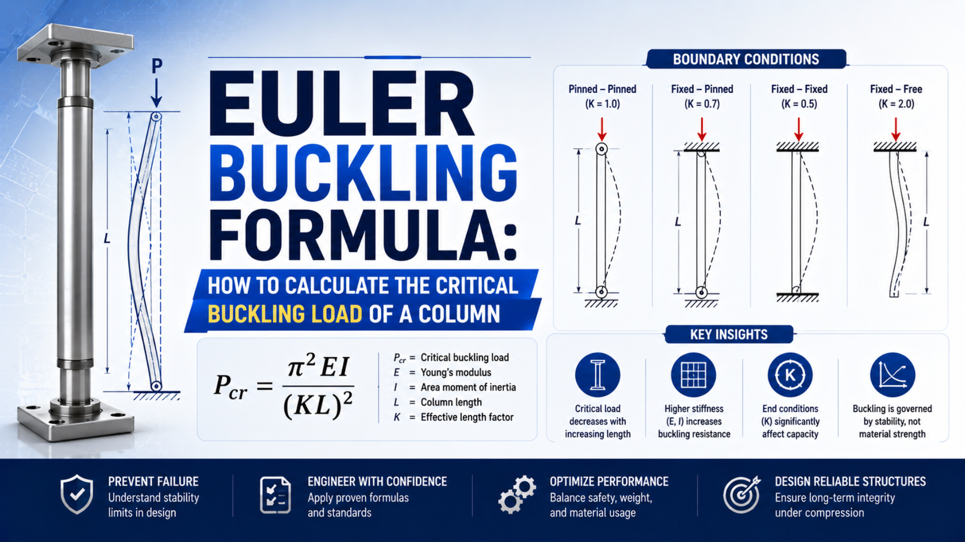
Euler’s buckling formula estimates the ideal elastic compression load at which a long, straight, slender column becomes laterally unstable. For a pneumatic cylinder rod, the calculation needs four defined inputs: Young’s modulus, the minimum area moment of inertia, the physical unsupported length, and an effective-length factor that represents end restraint. Stroke alone is not enough.
This article is a calculation worksheet. It shows how to construct the equation, keep units consistent, compare solid and hollow circular sections, and recognize when the result is outside Euler theory. For the wider machine-level workflow, including maximum compression cases, guides, side load, redesign choices, and rodless alternatives, use the long-stroke piston rod buckling guide.
Key Takeaways
- Euler load scales with rod stiffness and inversely with effective length squared.
- A solid circular rod’s inertia scales with diameter to the fourth power.
- Parker recommends a 3.5-to-5 security factor in its cited P1F method, not universally.
- A calculation screens the rod; the exact cylinder manufacturer’s chart governs selection.
What Does Euler’s Buckling Formula Calculate?
MIT describes Euler buckling as elastic instability of a long, slender column under axial compression and gives the effective-length form (MIT OpenCourseWare). The result is an ideal bifurcation load, not a material-breaking load or a complete cylinder rating.
The calculation is:
The effective length is:
Combining the two relationships gives:
In these equations:
- is the ideal Euler critical load in newtons.
- is Young’s modulus in when millimeter units are used.
- is the minimum centroidal area moment of inertia in .
- is the physical unsupported length in millimeters.
- is the dimensionless effective-length factor.
- is the effective buckling length in millimeters.
Euler critical load is the calculated axial compression load at which the ideal straight elastic equilibrium becomes unstable. It is not a guarantee that a real cylinder rod will remain straight up to that value. Initial curvature, load eccentricity, clearance, side load, local section changes, and imperfect restraint can reduce the usable load.
The formula also does not calculate cylinder thrust. Determine the maximum credible compression force separately, then compare it with a product-specific allowable load. SMC’s cylinder selection guidance instructs users to consider maximum generated cylinder force as a buckling force in its stroke tables, including a light-load cylinder stopped externally during extension (SMC).
The Input Worksheet: E, I, L, and K
MIT’s effective-length equation uses four quantities, , , , and , while ISO 15552 covers interchangeable cylinder dimensions for bores from 32 to 320 mm at a maximum rated pressure of 1,000 kPa (MIT, ISO). Dimensional standardization does not supply one universal buckling input set.
Record every value and its source before calculating:
| Input | Required record | Common mistake |
|---|---|---|
| Rod material, heat treatment, temperature, units, data source | Copying a generic steel value for an unknown rod | |
| Critical section shape and actual dimensions | Using piston bore or nominal thread diameter | |
| Worst-position unsupported physical length | Entering nominal stroke without checking adapters and supports | |
| End-restraint model or manufacturer mounting case | Assigning a theoretical value from the mount’s marketing name | |
| Maximum credible axial compression load | Using only routine payload force | |
| Manufacturer method or documented design basis | Treating one catalog’s factor as a universal rule |
Young’s modulus
Young’s modulus represents elastic axial stiffness. Use the value for the actual rod material and temperature, preferably from the manufacturer or controlled material data. Surface hardening or chrome plating does not automatically change the modulus of the entire rod section to the coating’s value.
An illustrative steel calculation often uses:
That number equals 200 GPa. It is an example input, not proof of the material in a purchased cylinder.
Unsupported physical length
Measure the physical distance over which the rod can bow at the worst extension position. Include exposed rod and any unsupported rod-end adapter required by the chosen method. A nominal 800 mm stroke can produce a different unsupported length if the piston, bearing, clevis, attachment, or external support changes the actual restraint points.
The value is geometry. The value is the equivalent length used in Euler’s equation. Keep them in separate worksheet cells so the source of the effective length stays visible.
Applied compression force
Use the largest credible axial compression force for the selected procedure. It may come from full regulated pressure against a jam or external stop rather than the normal payload. The Cylinder Force Calculator and the effective piston-area guide can establish the pressure-area part of this load case.
Don’t subtract an arbitrary efficiency percentage when the manufacturer’s buckling method explicitly asks for maximum generated force. Follow that method’s assumptions.
How Do You Select the Effective Length Factor K?
MIT lists four ideal end restraints and defines ; the pinned-pinned case has (MIT OpenCourseWare). The familiar factors 2.0, 1.0, about 0.7, and 0.5 belong to ideal columns, not automatically to cylinder mounting names.
| Ideal end condition | Theoretical | Relative Euler load at the same |
|---|---|---|
| Fixed-free | 2.0 | 0.25 |
| Pinned-pinned | 1.0 | 1.00 |
| Fixed-pinned | about 0.7 | about 2.04 |
| Fixed-fixed | 0.5 | 4.00 |
The relative load is calculated from with all other inputs unchanged. These values explain the influence of restraint. They do not prove that a flange is perfectly fixed or that a clevis behaves as an ideal pin in every plane.
Effective-length factor (K) is the coefficient that converts physical unsupported length into an equivalent Euler column length for a defined buckling mode and end-restraint model. It is not a correction for side load, misalignment, friction, impact, or an unknown support.
Map the real assembly before selecting :
- Identify where lateral translation is restrained at both ends.
- Determine whether each end can rotate in the likely buckling plane.
- Include bracket, rod eye, clevis pin, bearing, carriage, and machine-frame flexibility.
- Check whether restraint differs between two perpendicular planes.
- Use the cylinder manufacturer’s mounting case when its procedure defines one.
Festo’s published example uses a selected safety factor of five and approximates the unfavorable swivel-mounted buckling length as twice the stroke for that method (Festo). That is a model-specific rule. It does not make correct for every pivoted cylinder.
What if the end behavior cannot be defended? Use the more conservative documented case for screening, then obtain manufacturer review, a validated structural model, or a test. Do not invent an intermediate factor because the mechanism looks “partly fixed.”
How Do You Calculate I for Solid and Hollow Rods?
MIT gives for a solid circular section (MIT OpenCourseWare). Because diameter is raised to the fourth power, section measurement strongly affects the result. Use the smallest structural section that participates in column bending, not the piston bore or a decorative outside dimension.
For a solid circular rod:
Here, is the actual diameter of the evaluated rod section.
For a hollow circular rod:
Here, is outside diameter and is inside diameter. Keep both dimensions in the same unit.
For any section, calculate area and radius of gyration :
The slenderness ratio is:
Slenderness ratio is effective length divided by the section’s radius of gyration. A larger value indicates a more slender column, but it does not provide a universal pass-fail threshold for every material and product. Euler theory requires the predicted response to remain within the elastic, slender-column regime.
Unit combinations that close correctly
| Modulus | Inertia | Length | Result |
|---|---|---|---|
| N | |||
| Pa, or | m | N |
Do not insert in GPa directly into a millimeter equation. Convert it first. For example, becomes .
Threads, wrench flats, grooves, drilled passages, or diameter steps may create a smaller critical section. Whether that local feature governs global Euler buckling depends on its location, length, stiffness, and the selected structural model. Use the manufacturer’s defined rod diameter when its catalog supplies the method.
Worked Example: 20 mm Solid Rod at 800 mm
Parker’s P1F catalog calculates examples using maximum piston thrust and a four-fold buckling security check, while recommending 3.5 to 5 for that product procedure (Parker). The worksheet below uses a different ideal rod solely to demonstrate units and end-condition sensitivity.
Assume:
- solid rod diameter ;
- physical unsupported length ;
- illustrative steel modulus ;
- first case ;
- illustrative security factor ; and
- applied axial compression force .
First calculate the area moment of inertia:
Calculate effective length:
Then calculate ideal Euler load:
For the illustrative factor of four:
The screening ratio against the 4,000 N applied compression load is:
Now change only the ideal end condition to fixed-free, . Effective length becomes 1,600 mm, so the Euler load falls to one quarter:
With the same illustrative factor of four:
The 4,000 N applied load is below the first case’s illustrative allowable value but above the second. Nothing about the rod material or diameter changed. The restraint assumption alone reversed the screening result.
A spreadsheet that hides inside one “effective length” cell makes this error difficult to audit. Keep physical length and the end-condition factor visible, then record why the chosen restraint applies.
Why Does Diameter Matter More Than Length?
Combining MIT’s equations for Euler load and a solid circular section gives (MIT OpenCourseWare). With material and restraint unchanged, increasing diameter by 25% multiplies ideal load by about 2.44, while increasing effective length by 50% reduces it to about 0.44.
For two solid rods of the same material:
This ratio is useful because modulus and common constants cancel. It does not eliminate the need to check the actual rod diameter, effective length, applied force, and manufacturer’s limit.
Three sensitivity checks follow directly:
- Increasing diameter from 20 to 25 mm gives
${(25/20)^4 \approx 2.44}times the ideal load. - Increasing effective length from 800 to 1,200 mm gives
${(800/1200)^2 \approx 0.44}times the ideal load. - Changing from 1 to 2 gives
${(1/2)^2 = 0.25}times the ideal load.
A larger bore is not the same as a larger buckling margin. At unchanged pressure, bore increases maximum cylinder thrust. The corresponding rod may also grow, but the force increase and the section increase must be compared using the exact product configuration.
When Should You Stop Using the Euler Result?
Festo selects a safety factor of five in its published rod graph, while Parker recommends 3.5 to 5 for the cited P1F buckling procedure (Festo, Parker). Different methods prove that an isolated Euler result is not a universal product approval.
Stop treating the simple result as sufficient when:
- the member is short enough that yielding or inelastic buckling may govern;
- the calculated critical stress approaches the material’s proportional or yield range;
- load enters eccentrically or an initial bend is significant;
- the rod carries transverse load or guides the payload;
- support stiffness or end rotation cannot be mapped to a validated case;
- a threaded, grooved, hollow, stepped, or locally reduced section controls stiffness;
- pressure, impact, vibration, gravity, or a jam creates several compression cases;
- the manufacturer publishes a more restrictive stroke-load chart; or
- the consequence requires validated analysis or physical testing.
The Euler critical stress can be written as:
This form helps check whether the ideal critical stress remains in an elastic range. It does not provide the allowable material stress, a universal slenderness boundary, or a complete inelastic-column model.
Side load needs a separate calculation. Euler’s derivation assumes axial compression through an ideal straight member. A favorable critical load does not authorize the piston rod to support an offset payload. Review the linear-actuator side-loading guide and the piston-rod deflection guide when alignment or guidance is uncertain.
Use this evidence order:
- Establish the maximum credible compression load.
- Run the transparent Euler screen with recorded units and assumptions.
- Apply the exact product’s security-factor or allowable-load procedure.
- Check the current manufacturer stroke-load and mounting tables.
- Evaluate side load, impact, cushioning, brackets, and guides separately.
- Escalate to manufacturer review, FEA, or testing when the model boundary is not satisfied.
ISO 15552 confirms dimensional interchangeability for its defined cylinder family and pressure class. It does not publish one universal rod buckling capacity. Two dimensionally interchangeable cylinders can have different rod sizes, materials, permissible strokes, mounting cases, and catalog limits.
Euler Buckling Formula FAQs
SMC tells users to consider maximum generated cylinder force in its buckling tables, and Parker recommends a 3.5-to-5 factor in its cited P1F method. These five FAQs address the worksheet choices that most often change the result: physical length, , safety factor, pressure, and the boundary between an Euler screen and product approval.
Can I use cylinder stroke as unsupported length?
Not automatically. Stroke is actuator travel, while unsupported length is the physical column length able to bow at the worst machine position. Exposed rod, piston support, bearings, rod-end adapters, joints, and external supports can change it. Use the geometry and length definition required by the selected manufacturer method.
What K value should I use for a clevis-mounted cylinder?
A clevis may resemble an ideal pin in one plane, but the opposite end, bracket flexibility, bearing clearance, and load connection also control the buckling mode. Do not assign from the word “clevis” alone. Use the cylinder manufacturer’s mounting case or a documented structural model.
What safety factor should I apply to Euler load?
There is no universal pneumatic value. Parker recommends 3.5 to 5 in its cited P1F procedure, while Festo uses five in its referenced graph. Follow the exact cylinder’s method, then consider load uncertainty, dynamics, alignment, consequence, and applicable machine requirements before accepting the selected factor.
Does increasing air pressure change the Euler critical load?
Pressure does not directly change when , , , and stay unchanged. It can increase the cylinder’s applied compression force, which reduces the operating margin. Recalculate maximum thrust and compare it with the allowable buckling load whenever the regulated pressure changes.
Does passing the Euler calculation prove the cylinder is suitable?
No. The calculation screens ideal axial rod stability. Final selection still requires the exact manufacturer’s stroke-load table plus separate checks for side load, alignment, impact, cushioning, mount strength, pressure rating, speed, temperature, and environment. Use FEA or testing when the ideal-column assumptions do not represent the assembly.
Sources and technical references
- MIT OpenCourseWare, Elastic Buckling of Long Slender Columns, accessed July 23, 2026.
- SMC, Air Cylinders Model Selection Technical Data, accessed July 23, 2026.
- Festo, General Operating Conditions and Buckling Load Graph, accessed July 23, 2026.
- Parker, P1F ISO Pneumatic Cylinder Technical Catalogue, accessed July 23, 2026.
- ISO 15552:2018, Pneumatic Cylinders with Detachable Mountings, accessed July 23, 2026.