

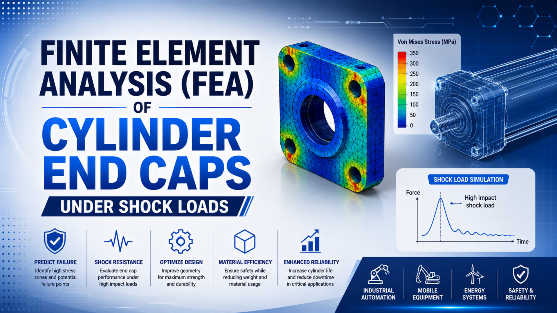
FEA of cylinder end caps under shock loads is a transient structural assessment of how a defined cylinder assembly responds to a short-duration pressure, contact, or base-motion event. A credible model starts with a measured load history, not an assumed impact multiplier. Model internal pressure, piston or cushion contact, barrel support, fastener preload, mount reactions, material nonlinearity, and contact behavior as separate inputs.
A single von Mises stress plot cannot establish shock-load capacity. It may show where one model concentrates stress, but it does not prove that the boundary conditions, peak load, material data, or fatigue life represent the installed cylinder.
Key Takeaways
- Pressure load, moving-mass energy, impulse, mount reaction, and bolt preload are different quantities.
- Linear static FEA is useful only when inertia, contact, damping, and material nonlinearity are demonstrably unimportant.
- Mesh convergence must use a physical response quantity, not the maximum stress at an ideal sharp corner.
- An explicit-dynamics solution needs energy and mass-scaling checks in addition to a stress review.
- Final acceptance requires correlation with instrumented pressure, acceleration, strain, displacement, or endurance data.
What Can FEA Actually Prove About a Cylinder End Cap?
FEA can estimate the response of a defined geometry, material model, assembly, and load history. For a cylinder end cap, useful outputs include:
- load transfer from the pressure boundary into the barrel, tie rods, bolts, threads, snap ring, or mounting feature;
- transient displacement and contact force during a cushion event or hard stop;
- nominal and local elastic-plastic strain at fillets, ports, grooves, bosses, and fastener seats;
- fastener separation, contact opening, slip, or preload loss;
- acceleration and reaction histories at the mount;
- fatigue input histories at physically meaningful hot spots.
FEA cannot recover an unknown impact pulse from a still image, prove material quality that was never specified, or turn an idealized sharp corner into a real fatigue prediction. It also cannot establish interchangeability. ISO 15552 standardizes principal dimensions and mounting interfaces for certain pneumatic cylinders; it does not certify a particular end cap against a shock spectrum.
The broader end-cap design guide covers pressure containment, mounting, materials, and service access. This article stays narrower: how to build, verify, and validate a transient structural model when the end cap sees a short-duration load.
The model should be organized as an evidence chain: measured event → assembly load path → numerical verification → hardware correlation → bounded operating decision. If one link is missing, report the gap instead of hiding it inside a larger safety factor.
Which Shock-Load Inputs Must Be Measured First?
Start with the event that the model must reproduce. “The piston hits hard” is not a load definition. Record the cylinder identity, bore, stroke, moving mass, piston and rod mass, speed before deceleration, operating pressure at both ports, cushion setting, external stop geometry, mount arrangement, and cycle rate.
A shock load is a force, pressure, or base-acceleration event whose short duration can make inertia, wave propagation, contact, or damping important to structural response.
Use high-speed measurements when the load changes faster than a normal PLC trend can resolve. Depending on the failure mode, that may require:
- pressure transducers near each cylinder port;
- an accelerometer on the end cap, carriage, or fixture;
- a position encoder or high-speed displacement sensor;
- a force washer, load cell, or instrumented stop;
- strain gauges beside the suspected hot spot;
- synchronized sampling with a documented trigger and bandwidth.
The pressure at a distant regulator is not the pressure-time history inside the end chamber. Tubing volume, valve flow, exhaust restriction, cushion geometry, temperature, and sensor location can change the local transient. The air-cushioning guide explains how trapped exhaust pressure produces deceleration near the end of stroke.
Define every load case separately:
| Load case | Required input | Typical model representation |
|---|---|---|
| Normal internal pressure | Measured or rated chamber pressure | Pressure on actual wetted surfaces |
| Cushion transient | Pressure versus time in the end chamber | Time-varying distributed pressure |
| Piston or stop contact | Relative velocity, contact geometry, stiffness, damping | Nonlinear contact or measured force-time input |
| Mount reaction | Installed bracket, pin, flange, or trunnion geometry | Explicit mount parts or justified remote constraint |
| Tie-rod or bolt preload | Assembly torque method and verified preload range | Pretension section or initial bolt load |
| External shock or vibration | Base acceleration or shock-response specification | Base-motion history or response-spectrum method |
| Thermal state | Gas, ambient, and component temperature | Temperature-dependent properties and thermal preload |
How Do Kinetic Energy, Stopping Distance, Pressure, and Impulse Differ?
Moving-mass kinetic energy before deceleration is:
Here, is the effective moving mass and is its velocity immediately before the stopping event. If a constant average stopping force acts over distance , an energy screening estimate is:
This is not the peak end-cap force. It omits continuing pneumatic drive work, gravity work, elastic energy, damping, rebound, and the shape of the force-time pulse.
For example, a 5 kg effective mass moving at 1 m/s carries 2.5 J. Stopping it over 5 mm requires an average inertial force of about 500 N; stopping it over 1 mm raises that average to about 2,500 N. The actual peak can be higher or lower depending on stiffness, damping, pressure history, contact duration, and rebound.
Internal pressure creates a distributed resultant:
Here, is chamber gauge pressure and is the actual projected wetted area for the load path being considered. Do not add this force to an impact peak unless both occur at the same time and direction in the measured event.
Impulse describes force acting over time:
Two events can transfer the same impulse while producing different peak forces because their durations differ. This is why a static equivalent load based only on momentum or energy cannot reproduce every shock event.
Festo’s 2026 DSBC catalog provides a useful scale check: maximum end-position impact energy for the standard 32–125 mm bore range is listed from 0.4 J to 3.3 J, depending on size. A DAMT trunnion-mount note limits maximum energy to 0.1 J. These are configured-product limits, not universal FEA inputs (Festo DSBC catalog).
Use the Cylinder Cushion Energy Calculator only to screen moving-mass energy and continuing drive work. It does not calculate end-cap stress, contact force, bolt preload loss, or fatigue life.
When Is Linear Static FEA Insufficient?
Linear static FEA can be a useful first screen if the structure remains elastic, contact status does not change, deflection is small, loading is slow relative to the structure’s natural periods, and a justified equivalent static load represents the event. Document why each condition is satisfied.
Use transient analysis when any of the following matters:
- the load duration is comparable with a structural natural period;
- inertia changes the reaction or stress distribution;
- the piston, cushion spear, bumper, stop, or mount makes or loses contact;
- fastener preload changes or joint faces separate;
- rubber or polymer components contribute important nonlinear stiffness;
- local yielding redistributes stress;
- rebound produces a second load pulse;
- pressure and contact loads peak at different times.
An implicit transient solver is often efficient for moderate nonlinearity and longer events. An explicit solver is often practical for severe contact, short-duration impact, and complex separation. Solver choice does not remove the need for a physical load history and convergence evidence.
Abaqus states that total energy should remain approximately constant in an adiabatic explicit-dynamics model and that artificial energy terms should remain negligible relative to the real energies (Abaqus/Explicit dynamic analysis documentation). If mass scaling is used to enlarge the stable time increment, document the added mass, its location, and its effect on inertia. Abaqus also cautions that dynamic accuracy requires correct physical mass and inertia (Abaqus mass-scaling documentation).
How Should the End Cap, Barrel, Fasteners, and Mount Be Constrained?
Model enough of the assembly to reproduce stiffness and load transfer. A fully fixed cut face at the end cap can suppress rotation, overstate local stress, and bypass the fasteners or barrel contact that carry the real reaction.
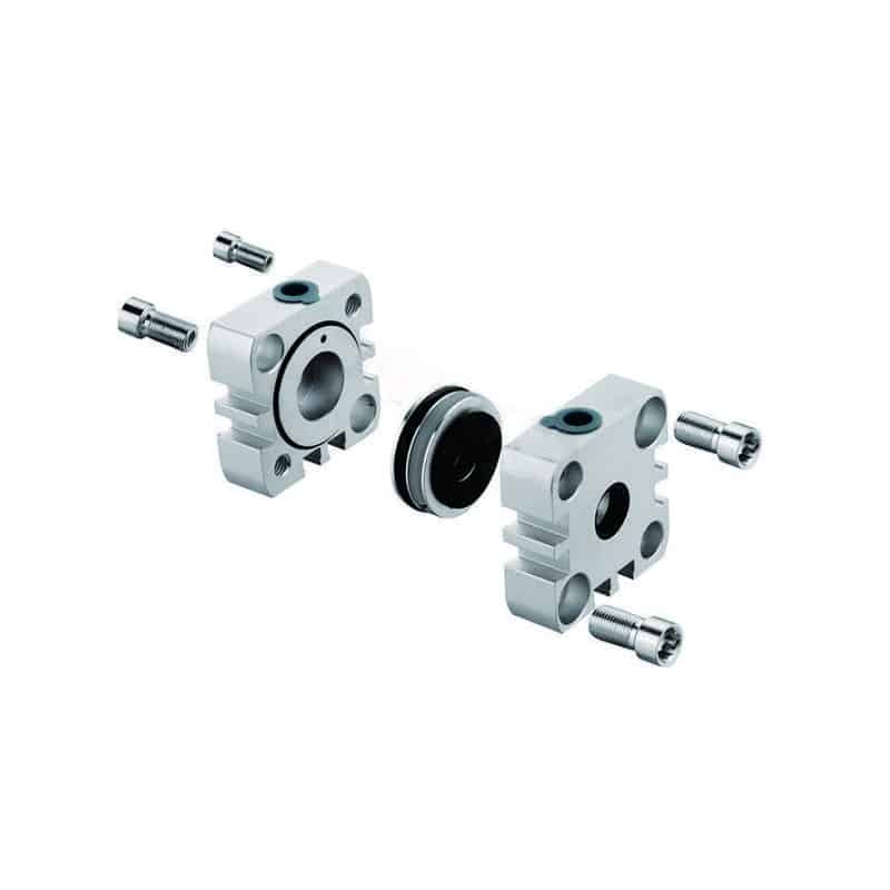
An exploded cylinder assembly helps identify the parts that control the end-cap load path. Product appearance alone does not define contact stiffness, preload, material, or shock capacity.
Include or justify simplification of:
- Barrel-to-cap interface: flange, crimp, thread, retaining ring, tie rod, or bolted joint.
- Fasteners: preload range, thread engagement, head or washer contact, and possible separation.
- Seals and grooves: pressure boundary and contact only where they change structural response; do not assign a seal the stiffness of a metal support.
- Ports and cross holes: retain them when they interrupt the stress path near the hot spot.
- Mount: reproduce pin freedom, bracket flexibility, flange contact, trunnion bearing, or clevis clearance.
- Symmetry: use it only when geometry, preload, contact, mounting, and time-dependent loading are symmetric.
Pretension from assembly torque is uncertain unless the torque-tension relationship and friction are controlled. Use a preload range or measured bolt elongation rather than one falsely precise value. For tie-rod assemblies, the tie-rod failure analysis explains why thread roots, preload imbalance, and mount flexibility need separate attention.
In our experience reviewing pneumatic assemblies, a load-path sketch usually resolves the first modelling dispute faster than a denser mesh. It makes the team name the pressure boundary, contact pair, preload path, and mount freedom before comparing contour plots.
Which Material, Contact, and Bolt Models Are Required?
Use the actual material specification and condition: alloy, temper, casting process, heat treatment, surface treatment, and minimum property basis. A generic “aluminum” curve is not enough for a cast end cap that contains a local fillet, porosity population, and machined port.
For elastic screening, record Young’s modulus, Poisson’s ratio, density, and temperature. For local yielding, add a true-stress versus plastic-strain curve and a defensible hardening model. For cyclic plasticity or low-cycle fatigue, use data that represents the material, manufacturing condition, mean stress, surface finish, and temperature.
Contact inputs also need evidence:
- normal contact formulation and penetration tolerance;
- friction coefficient range;
- damping or compliant-layer representation;
- gap and interference;
- fastener preload;
- seal, bumper, or polymer stiffness versus strain rate and temperature.
Do not use a high friction coefficient to stabilize a model numerically unless it represents the assembly. Do not report contact-edge peak stress as a material failure result without checking whether the geometry contains the real radius and whether the stress converges away from the edge.
How Do You Build a Mesh-Convergence and Time-Step Study?
Mesh refinement should answer whether a decision-relevant quantity is stable. Track several responses, such as:
Mesh convergence means that a selected physical response approaches a stable value as the spatial discretization is systematically refined.
- end-cap displacement at a defined point;
- reaction force and impulse at the mount;
- bolt force or joint opening;
- contact force and contact duration;
- volume-averaged or path stress away from a singular edge;
- elastic-plastic strain range at a real fillet;
- total, kinetic, internal, contact, hourglass, and artificial energies.
Run at least three systematically refined meshes around the load path. State element formulation, order, size, local refinement, contact discretization, and quality metrics. A maximum nodal stress that rises without limit at a perfectly sharp re-entrant corner is not a convergence metric. Ansys notes that sharp corners, point loads, and point restraints can create stress singularities whose maximum stress does not converge (Ansys stress-singularity lesson).
For transient work, refine the output interval and solver time control as well as the spatial mesh. Compare peak force, impulse, contact duration, displacement, strain history, and energy balance. If those outputs shift materially as the time increment is reduced, the earlier solution is not time-converged.
Use a table like this in the analysis report:
| Study | Change made | Displacement | Peak contact force | Hot-spot strain range | Energy or residual check | Decision |
|---|---|---|---|---|---|---|
| M1/T1 | Baseline mesh and time control | Record | Record | Record | Record | Not accepted alone |
| M2/T1 | Local mesh refined | Compare | Compare | Compare | Compare | Check spatial convergence |
| M3/T1 | Further local refinement | Compare | Compare | Compare | Compare | Establish mesh trend |
| M3/T2 | Smaller time increment/output interval | Compare | Compare | Compare | Compare | Establish time trend |
| M3/T3 | Reduced or removed mass scaling | Compare | Compare | Compare | Compare | Establish inertia sensitivity |
Set acceptance tolerances before viewing the preferred result. A project may use different limits for displacement, bolt force, strain, and energy error, but the criteria should follow the consequence of error and the available validation accuracy.
Which Results Matter Beyond a Von Mises Heat Map?
Review the complete response history, not only the frame with the highest color value. The most useful plots usually include:
- pressure, contact force, mount reaction, and acceleration versus time;
- displacement and joint opening versus time;
- bolt force versus time;
- principal stress and strain direction at likely crack origins;
- plastic strain accumulation;
- contact status and slip;
- energy histories;
- section forces through the barrel-cap joint;
- a path or averaged result around a real fillet.
Von Mises stress is appropriate for screening yielding in many ductile metals. It is not a complete criterion for brittle castings, threaded joints, adhesive interfaces, seal extrusion, or crack growth. Maximum principal stress, strain range, bearing stress, fastener utilization, fracture-mechanics quantities, or a material-specific failure model may be more relevant.
Also review timing. If the mount reaction peaks after chamber pressure or a second peak follows rebound, a single combined static load can conceal the governing state.
How Should Repeated Shock Loads Become a Fatigue Assessment?
Do not claim that an FEA model has “tested thousands of impacts” merely because the solver ran one transient. Extract a stabilized stress or strain history at a mesh-converged physical location, count the relevant cycles, and apply fatigue data that matches the material and manufacturing condition.
For a linear-elastic, high-cycle assessment, stress-life data may be suitable after applying mean-stress, surface, size, notch, temperature, and reliability corrections. Where local plastic strain occurs, strain-life or another nonlinear fatigue method is usually more appropriate.
For variable-amplitude loading, a common screening model is Miner’s linear damage sum:
Here, is the applied count at range and is the estimated life at that range. This model does not capture every load-sequence, overload, residual-stress, corrosion, or crack-closure effect. Treat it as one fatigue model, not a universal proof.
Abaqus notes that directly simulating every cycle can be prohibitively expensive and instead uses a small fraction of cycles with fatigue-law extrapolation in its direct cyclic approach (Abaqus low-cycle fatigue documentation). The fatigue method still needs representative loading and physical correlation.
Inspect real fracture origins and manufacturing records. Porosity, cold shuts, machining marks, thread damage, uneven tie-rod preload, and corrosion can dominate life even when nominal model stress looks acceptable.
How Do You Verify the Model with Physical Tests?
ASME V&V 10-2019 (R2025) provides a framework for verification, validation, and uncertainty quantification in computational solid mechanics (ASME V&V 10). Validation is the assessment of how accurately the computational model represents the real system for its intended use. Apply the distinction directly:
- Verification: Did the equations solve correctly for the selected model? Check mesh, time-step, energy, contact, and solver sensitivities.
- Validation: Does the model represent the real cylinder for its intended use? Compare predictions with measured physical response and quantify the mismatch.
Build validation in stages:
- Check mass, center of gravity, fastener preload, and static pressure deformation.
- Correlate modal frequencies or low-level dynamic response where relevant.
- Run a subcritical cushion or impact event with synchronized pressure, motion, acceleration, and strain.
- Compare waveform shape, timing, contact duration, peak, impulse, and residual deformation.
- Quantify sensor uncertainty and model discrepancy.
- Increase severity only within an approved test plan and guarded safety envelope.
- Inspect the end cap, fasteners, barrel joint, seals, and mount after the test.
ISO 10099 defines final examination and acceptance criteria for certain double-acting single-rod pneumatic cylinders. It can support a product test plan, but it does not replace project-specific shock validation or computational V&V.
What Should an FEA Review Package Contain?
A reviewer should be able to reproduce the engineering decision without guessing which load, material, or constraint was used. Include:
- model objective and excluded failure modes;
- drawing revision, defeaturing record, and manufacturing condition;
- all load histories with source, bandwidth, synchronization, and uncertainty;
- material sources and temperature or rate dependence;
- fastener preload and contact assumptions;
- solver type, controls, element formulations, and software version;
- mesh and time-step convergence tables;
- energy, residual, artificial-energy, and mass-scaling checks;
- hot-spot extraction method and singularity treatment;
- acceptance criteria established before final result review;
- fatigue method, cycle spectrum, correction factors, and uncertainty;
- physical test setup, sensor calibration, comparison plots, and discrepancy;
- approved operating envelope and unresolved risks.
Keep the conclusion bounded. “Passes the analyzed 6 bar pressure history and measured 0.8 m/s stop event with the documented mount and preload range” is reviewable. “The optimized cap will never crack” is not.
If a design fails, change the load path before simply thickening the cap. Reduce entry speed, increase stopping distance, correct cushion adjustment, add a rated external shock absorber, stiffen the mount, enlarge a real fillet, move a port away from a critical ligament, or control preload. The external shock-absorber guide and end-of-stroke force guide cover the upstream changes that can reduce the transient.
Cylinder End-Cap FEA FAQs
Can I replace a transient impact with a static safety factor?
Only after demonstrating that inertia, contact, damping, load duration, joint opening, and material nonlinearity do not change the governing response. A static multiplier may be useful for a calibrated family of similar events, but it is not a universal substitute for a measured force-time or pressure-time history.
Is the highest von Mises stress the failure location?
Not necessarily. The maximum may occur at a singular corner, point restraint, contact edge, or mesh artifact. Check convergence, actual radii, stress or strain over a physical distance, principal direction, material failure mode, manufacturing defects, and fracture evidence before naming a crack origin.
How fine should the mesh be around an end-cap fillet?
Fine enough that decision-relevant displacement, reaction, bolt load, contact force, and hot-spot stress or strain stabilize under systematic refinement. There is no universal element size. Geometry radius, element order, material nonlinearity, contact, and the required accuracy determine the mesh.
Does passing ISO 15552 prove shock-load strength?
No. ISO 15552 addresses principal dimensions, mounting interfaces, and interchangeability for a defined cylinder class. Shock-load capacity remains product- and application-specific and requires manufacturer limits, analysis, and validation for the installed load path.
Can FEA predict end-cap fatigue life exactly?
No. It can provide stress or strain histories for a stated model. Fatigue life also depends on material scatter, casting quality, surface condition, preload, mean stress, environment, load spectrum, and the chosen damage model. Report a range or reliability basis and validate with representative hardware.
Sources and Technical References
- ASME V&V 10-2019 (R2025), Verification and Validation in Computational Solid Mechanics
- Abaqus, Explicit Dynamic Analysis
- Abaqus, Mass Scaling
- Abaqus, Direct Cyclic Low-Cycle Fatigue
- Ansys, Assessing Stress Singularity
- Festo, DSBC Standards-Based Cylinders
- ISO 10099:2001, Pneumatic Fluid Power—Cylinders—Final Examination and Acceptance Criteria
- ISO 15552:2018, Pneumatic Fluid Power—Cylinders with Detachable Mountings
Conclusion: Treat FEA as a Verified Model, Not a Color Plot
End-cap shock capacity depends on the complete chain from measured motion and pressure through contact, preload, barrel support, mounting, material, and manufacturing condition. Calculate energy and pressure separately, select a solver that matches the event, prove mesh and time-step convergence, audit numerical energy, and correlate the predicted histories with hardware.
That process will not promise an exact service life. It will produce something more useful: a traceable operating envelope, known uncertainty, and a clear list of design changes if the present end cap, stop, cushion, fastener, or mount cannot carry the measured event.
For help reviewing a cylinder drawing, measured shock event, FEA report, or replacement configuration, send the model identity, operating pressure, motion data, mount details, and available test evidence through our technical contact page.