

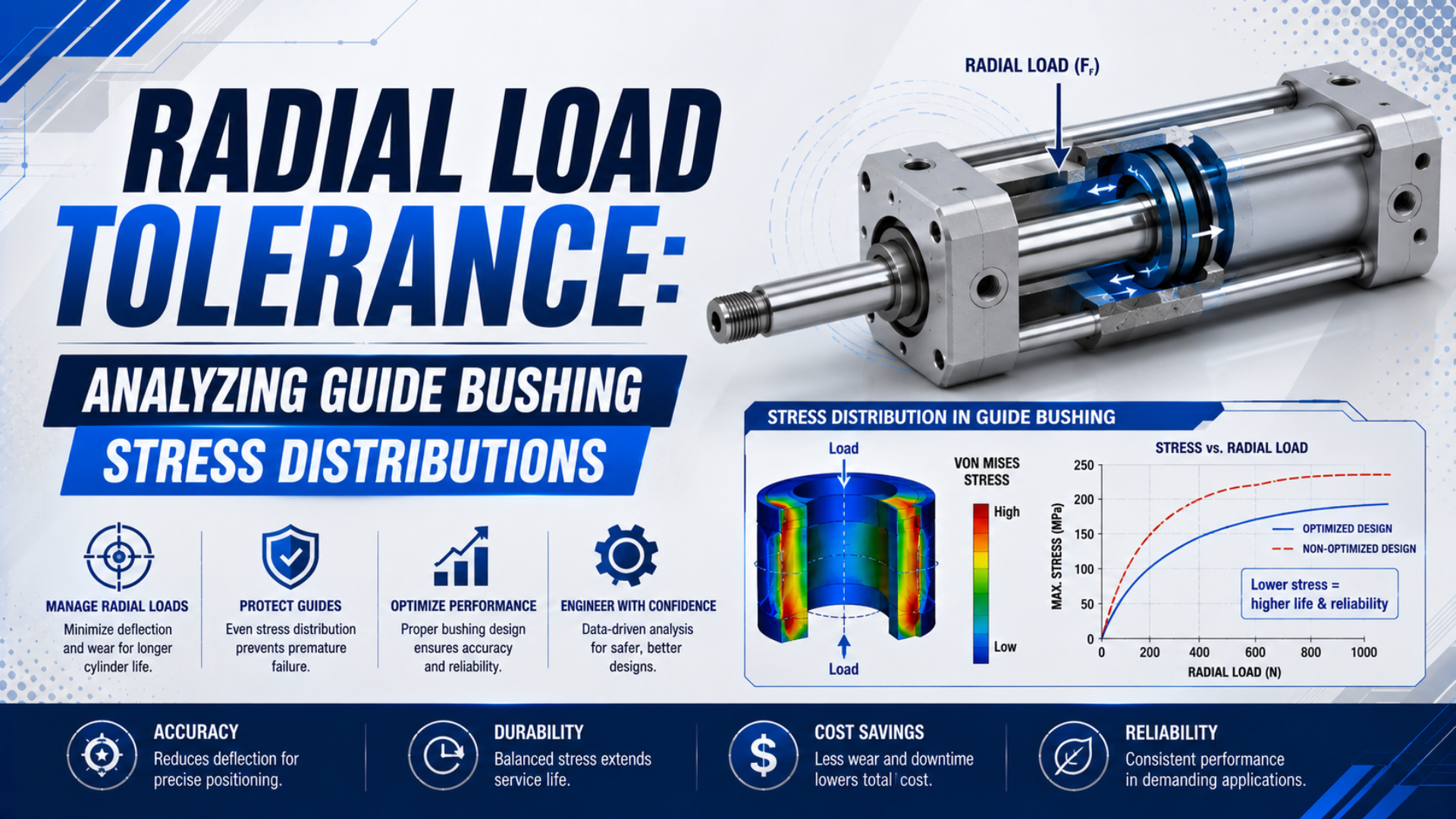
Radial load tolerance is not one universal force that a pneumatic-cylinder guide bushing can carry before it deforms. It is a model-specific operating boundary shaped by transverse force, load offset, rod extension, support spacing, bearing geometry, clearance, speed, lubrication, temperature, and duty. The manufacturer’s allowable side-load curve remains the final authority.
A useful engineering screen begins one step earlier than most catalog checks: convert the external side force and its offset into reactions at the head bushing and rear piston support. Then calculate nominal projected pressure. That result can expose an obviously poor load path, but it cannot predict the true peak contact stress or certify cylinder life by itself.
Key Takeaways
- An offset force can make the head-bushing reaction exceed the applied side force.
- Projected pressure uses bushing diameter and effective length, but it is not peak edge stress (igus).
- Material limits depend on pressure, speed, temperature, counterface, and lubrication.
- Loads outside the configured cylinder limit need independent guidance.
This article isolates the calculation behind bushing loading. For the complete failure path from side load to rod scoring and seal leakage, read how cylinder side-loading affects rod-bearing and seal wear.
What Does Radial Load Tolerance Actually Mean?
SMC publishes allowable lateral load as a stroke-dependent curve and warns that excessive load can damage the bushing, rod surface, tube, and seals (SMC Cylinder Operation Manual, accessed 2026). Radial load tolerance must therefore be taken from the exact cylinder configuration, not inferred from bore or axial thrust alone.
The terms below describe different quantities:
| Quantity | Meaning | Appropriate use |
|---|---|---|
| External radial load, | Force acting perpendicular to the stroke axis | Define the machine load vector |
| Offset moment, | Transverse force multiplied by its lever arm | Show how an overhung load challenges the support system |
| Support reaction, | Force transferred through the head bushing or rear support | Estimate which internal support is most heavily loaded |
| Average projected pressure, | Reaction divided by projected bearing area | Screen a specific bearing material and geometry |
| Peak contact pressure, | Highest local pressure in the real contact zone | Requires a more detailed contact model, validated simulation, or test |
| Catalog allowable side load | Manufacturer’s permitted load under stated conditions | Product selection and release decision |
Axial cylinder force is absent from that list for a reason. Increasing bore or air pressure may help the actuator overcome friction, but it does not remove a transverse load or its moment. A strong cylinder can still be a poor guide.
The allowable boundary may be reached before any visible plastic deformation. Excessive friction, stick-slip, local wear, heat, loss of seal concentricity, rod deflection, or piston-guide damage can end acceptable operation first. That is why “no permanent deformation” is too narrow a definition of tolerance.
How Does an Offset Side Force Load the Guide Bushing?
A 100 N transverse force acting 300 mm beyond the head bushing, with 100 mm between the head and rear supports, produces a 400 N head reaction in a two-support static model. SMC’s warning against excessive lateral load supports using the real force geometry rather than an axial-force percentage (SMC, accessed 2026).
Begin with the overhung moment:
Here, is the external moment in N·m, is the transverse force in newtons, and is the distance in meters from the head-bushing reaction plane to the load line.
Now idealize the rod and piston assembly as a rigid member supported at two reaction planes. Let be the distance between the head bushing and the rear piston support. Static equilibrium gives:
is the head-bushing reaction and is the rear-support reaction. The negative sign means the rear reaction acts opposite to the head reaction under the selected sign convention. These are reaction forces, not material stresses.
For the example, is 100 N, is 0.30 m, and is 0.10 m:
The reactions balance the 100 N external load, and their force couple balances the 30 N·m external moment. Short support spacing and long overhang are the dangerous combination.
The applied side force is not necessarily the largest force inside the support system. In this example, the head bushing reacts 4 times the external load. That amplification is why a light tool mounted far from the support can be harder on a cylinder than a heavier load carried close to an independent guide.
This rigid two-support model is deliberately simple. Real piston guidance has finite length and clearance, the rod bends, and the reaction planes can shift. Use the calculation to understand load transfer, then verify the geometry against drawings, catalog curves, and measurements. For rod-flexure effects, see the companion piston-rod deflection calculation guide.
Average Projected Pressure Is a Screening Value
igus calculates radial-bushing surface pressure from load divided by diameter times bearing length, so a 20 mm bore and 20 mm length provide a 400 mm² projected area (igus Surface Pressure and Load, accessed 2026). This method is useful for screening, not for reconstructing the actual pressure field.
For a cylindrical guide bushing, the nominal projected area is:
is the projected area in mm², is the supported rod diameter or bushing bore in millimeters, and is the nominal bearing length in millimeters.
Average projected pressure is:
With the 400 N head reaction, a 20 mm rod, and a 20 mm nominal bushing length:
That 1 MPa value is a nominal screening result. It does not mean every point in the bushing sees 1 MPa, nor does it establish an allowable cylinder side load.
SKF illustrates why formulas must match the actual bearing construction. Its filament-wound bushing guide uses rather than the full nominal width for that product family and evaluates specific load together with sliding speed on a PV diagram (SKF Filament Wound Bushings, accessed 2026). A pneumatic-cylinder manufacturer may use another effective length, contact model, or empirical limit.
In our application reviews, we record projected pressure as a screening line item, not an approval result. If the drawing, material designation, or effective bearing length is missing, we request that information before comparing the number with any allowable value.
Use this screening sequence:
- Calculate the actual transverse load, including gravity, acceleration, tool contact, hose drag, and stop reactions.
- Resolve the load into the manufacturer’s defined axes.
- Calculate the reactions using the best available support geometry.
- Use the specified effective bearing area, not an assumed visible length.
- Compare pressure and speed with data for the exact bushing material and counterface.
- Check the complete cylinder’s allowable lateral-load and moment curves.
If the bushing dimensions or support separation are unknown, stop. A guessed area can create a precise-looking answer with no defensible physical basis.
Why Does Peak Edge Stress Differ From the Average?
igus states that is an approximation because every part of a cylindrical bearing does not carry equal load; it also calls out edge pressure and PV as additional checks (igus Engineering Toolbox, accessed 2026). Average projected pressure therefore cannot be substituted for peak contact pressure.
The distribution changes when the rod rotates within its diametral clearance or bends under the applied moment. Contact can migrate toward one axial edge and one circumferential sector. Housing distortion, assembly error, temperature, rod straightness, surface waviness, and an imperfectly aligned external guide can shorten the effective contact zone further.
A simple sensitivity check makes the risk visible. If only 10 mm of the nominal 20 mm length carries most of the 400 N reaction, the effective-area estimate becomes:
Halving assumed contact length doubles the screening pressure. The real peak may still be higher because the pressure field is not uniform.
Rather than report one false-precision result, calculate a bounded screen using the nominal length and a justified shorter effective length. If that range approaches the material or catalog limit, the design needs manufacturer review, a validated contact model, finite-element analysis with realistic clearance and stiffness, or an instrumented test.
Do not use Hertzian line-contact equations automatically. A conformal cylindrical bushing with clearance, a layered composite sleeve, and a short edge-loaded contact zone does not behave like two ideal nonconforming elastic bodies. The correct model depends on geometry, material constitutive behavior, interference or clearance, and support stiffness.
Material, Speed, and Lubrication Change the Limit
igus lists maximum surface pressure at 68°F as a material-specific static comparison and limits that condition to very slow motion, up to 1.97 ft/min; individual materials differ (igus, accessed 2026). A “bronze versus polymer” label cannot replace the exact pressure, speed, temperature, and lubrication data.
When a supplier provides a PV method, the basic screen is:
is the selected pressure measure in N/mm² or MPa, and is sliding velocity in m/s. Confirm the supplier’s units and whether its curve uses average projected pressure, peak pressure, continuous speed, oscillating speed, or another definition. Don’t compare PV numbers across unrelated materials without matching the test method.
Review at least these factors:
| Factor | Why it changes bushing behavior | Data needed |
|---|---|---|
| Bushing construction | Sintered metal, wrapped composite, machined polymer, and filled PTFE layers carry and dissipate load differently | Exact material designation and supplier limit |
| Counterface | Rod hardness, coating, roughness, waviness, and damage affect friction and wear | Rod specification and inspection result |
| Lubrication | Boundary lubrication, grease compatibility, replenishment, and contamination change friction and heat | Approved lubricant and maintenance condition |
| Temperature | Material strength, clearance, viscosity, and seal behavior shift with temperature | Stabilized operating and ambient range |
| Speed and duty | Sliding heat and lubricant transport depend on velocity, stroke, reversals, and dwell | Speed profile, cycle rate, and daily duty |
| Edge geometry | Chamfers, relief, bearing length, and housing support influence edge concentration | Section drawing or manufacturer model |
SKF’s filament-wound guide treats specific bearing load and sliding speed together on a PV diagram, and directs users outside the published curve to application engineering (SKF, accessed 2026). Apply the same discipline to cylinder bushings: use the actual component’s data, not a generic material stereotype.
Diagnosis Should Preserve Directional Evidence
SMC requires piston-rod and load centerlines to match and warns that misalignment can wear the tube, bushing, rod surface, and seals (SMC, accessed 2026). Four related observations, load direction, bushing contact sector, rod scoring, and stroke position, should agree before radial overload becomes the leading diagnosis.
Follow the machine’s approved energy-control procedure before hands-on inspection. Secure suspended loads, isolate every energy source, exhaust trapped pressure, and verify the safe state. Observe motion only under the site’s controlled diagnostic procedure.
Before cleaning or removing parts:
- Mark 12 o’clock on the cylinder head, gland, rod, and mount.
- Record the payload, center-of-gravity offsets, stroke position, direction, speed, pressure during motion, and operating temperature.
- Photograph lubricant, debris, rod marks, and leakage in their installed orientation.
- Compare free movement at retracted, mid-stroke, and extended positions.
- Repeat the approved alignment check unloaded and under representative load.
- Measure rod runout, bushing clearance, rod diameter, and surface condition using the manufacturer’s fixture and limits.
| Evidence pattern | Radial-load interpretation | Competing cause |
|---|---|---|
| Bushing polish and rod scoring share one clock position | Directional support reaction is plausible | Trapped hard particle in the same sector |
| Binding increases with extension | Overhang, rod deflection, or crossing guide axes may be increasing | Bent rod or bracket deflection |
| Wear reverses between stroke ends | Cylinder and external guide axes may intersect | Moving frame or joint constraint |
| Uniform lip hardening or cracking | Side load is not the leading explanation | Temperature or material incompatibility |
| Random scratches around the rod | Directional bearing load is less likely | Contamination or damaged wiper |
| Leakage returns after seal replacement | The load path or rod surface may remain defective | Wrong kit or installation damage |
In our experience, a credible diagnosis is directional. If the external reaction points downward but the bushing, rod, and seal all show dominant wear at an unrelated clock position, keep the fault tree open. Parts rotated during disassembly can erase this comparison, so orientation marks are as valuable as the later dimensional measurements.
The detailed component sequence is covered in how rod bearings prevent repeat rod-seal failures.
When Should an External Guide Carry the Load?
SMC specifies a maximum mating-surface flatness of 0.03 mm for the MY1 slide-table mounting interface and, when an external guide is used, instructs that guide to carry the load while the cylinder supplies drive force (SMC MY1B Operation Manual, accessed 2026). “Rodless” alone is not a radial-load rating.
Choose the architecture by load path:
| Application condition | Preferred arrangement | Required verification |
|---|---|---|
| Load already travels on a linear rail | Standard cylinder connected through an aligned or approved floating joint | Rail forces, connection freedom, parallelism, and stop location |
| Tool must resist pitch, yaw, or roll moment | Guided cylinder or guided carriage | Ratings for every force and moment axis at the actual center of gravity |
| Long overhung tool sits on a piston rod | Independent guide or supported carriage | Maximum-extension force, moment, rod deflection, and structural stiffness |
| Compact rodless layout is required | Select a specifically guided rodless actuator or pair a drive-only type with an external guide | Configured carriage-load diagrams, mounting flatness, and load factor |
| Small connection error remains after alignment | Manufacturer-approved floating joint | Eccentricity, angular freedom, thread engagement, and full-stroke clearance |
A basic mechanical-joint rodless cylinder may include some guidance, but the exact model still has allowable load factors, moments, mounting-flatness requirements, and support-spacing limits. A drive-only rodless arrangement can also need an external guide. Compare configured models, not generic architecture names.
For the broader retrofit process, use how to mitigate side load in linear-cylinder applications. Guided-cylinder choices are compared in the compact guide-cylinder selection guide.
Before releasing a design, send the supplier:
- Cylinder series, bore, stroke, rod diameter, mount, and cushioning option
- Payload and tooling mass
- Center-of-gravity offsets in all axes
- Static, acceleration, process-contact, hose, and stop forces
- Speed profile, cycle rate, dwell, and daily duty
- Mounting orientation and external-guide arrangement
- Ambient temperature, contamination, washdown, and lubricant constraints
- Required life and acceptable clearance, friction, leakage, and positioning criteria
The supplier should return configured allowable force and moment data, the reference point used for each moment, required mounting tolerance, and any derating rule. If those items are missing, a projected-pressure calculation cannot fill the gap.
The Calculation Is a Screen, Not a Cylinder Rating
SKF uses the product-specific area for one filament-wound bushing family, while igus uses as a practical approximation for radial plastic bushings (SKF; igus, accessed 2026). Even the projected-area definition depends on the specific bearing construction and supplier method.
Use the two-support reaction model to expose lever-arm amplification. Use projected pressure to screen an identified bushing material under stated conditions. Then compare the complete machine load case with the exact cylinder’s side-load and moment limits.
Stop the calculation and escalate when the internal support spacing is unknown, contact length is assumed, the load changes dynamically, housing compliance matters, the bushing material lacks verified limits, or the result sits near a published boundary. In those cases, obtain manufacturer analysis, a validated simulation, or application-specific test data.
That hierarchy keeps each result in its proper place: equilibrium explains the load path, projected pressure screens the bearing, and configured manufacturer data decides whether the cylinder is suitable.
Radial Load and Guide Bushing FAQs
SMC separates at least 4 checks relevant to a side-loaded rod: the allowable lateral-load curve, centerline alignment, floating-joint limits, and full-stroke freedom with an external guide (SMC, accessed 2026). These answers preserve those boundaries rather than inventing one universal radial-load percentage.
Can radial load tolerance be calculated as a percentage of cylinder thrust?
No. Axial thrust comes from pressure and piston area, while radial-load capacity depends on stroke, rod extension, support geometry, bearing construction, mounting, and duty. SMC publishes lateral load as a separate stroke-dependent limit. A thrust percentage can hide a harmful offset moment even when the cylinder has ample axial force.
Is average bushing pressure the same as maximum contact stress?
No. The projected-area equation assumes a simplified load-bearing area. igus states that is an approximation because the load is not uniform and edge pressure still matters. Peak contact stress requires a model or test that includes clearance, rod bending, material behavior, housing stiffness, alignment, and the actual contact length.
Does a longer guide bushing always increase radial load capacity?
Not automatically. A longer nominal length increases projected area, but only the effective loaded length contributes to the pressure screen. Misalignment or rod deflection can shift contact toward one edge. Friction, PV, housing support, lubrication, and the complete cylinder’s allowable-load curve must still be checked for the configured product.
Are polymer guide bushings always better than bronze under side load?
No. Polymer, composite, and sintered-metal bushings cover many formulations and constructions. Capacity depends on the exact material, counterface, clearance, temperature, speed, lubricant, edge geometry, and test method. Compare supplier pressure and PV data for the identified part instead of choosing from a broad material label.
Can a rodless cylinder replace an external guide?
Only when that exact rodless model is rated for the applied forces and moments. SMC instructs external guides to carry the load when they are used with MY1 cylinders and identifies MY1B as suitable as a driving source. Verify carriage load, moment axes, mounting flatness, stroke, speed, and load factor before selection.
Sources and technical references
- SMC Cylinder Operation Manual, DOC1114537, allowable lateral load, alignment, bushing and seal damage, and external-guide connection; retrieved 2026-07-23.
- SMC MY1B Operation Manual, DOC1120098, guide load factor, external-guide load path, mounting flatness, and MY1B drive-source guidance; retrieved 2026-07-23.
- SKF Filament Wound Bushings, product-specific projected area and PV selection; retrieved 2026-07-23.
- igus Surface Pressure and Load, radial-bushing surface pressure and material-specific static limits; retrieved 2026-07-23.
- igus Engineering Toolbox: How to Calculate Surface Pressure, projected-area approximation, edge pressure, and PV caveats; retrieved 2026-07-23.