


Organize pneumatic hoses by separating fixed distribution, machine drops, moving axes, portable tools, pedestrian crossings, and service loops. Route each zone with hardware suited to its motion, then control the complete assembly’s pressure rating, bend radius, couplings, isolation, inspection, and replacement status.
That distinction matters. A ceiling drop that feeds a handheld tool should not be managed like a hose moving inside a cable carrier. Nor should a flexible hose replace properly designed fixed distribution simply because it is easier to install. Good hose management starts with the application and movement, not the color of the hose.
Pneumatic hose is a flexible, usually reinforced conduit designed for compressed-air service. Pneumatic tubing is a lighter, often semi-rigid line used between valves, manifolds, and actuators. Fixed pipe forms the plant distribution network. Each requires different support, protection, and inspection decisions.
Key Takeaways
- OSHA 1910.22 requires walking-working surfaces to be inspected regularly and kept free of hazards.
- ISO 2398:2024 covers compressed-air rubber hose up to 2.5 MPa, but the actual product rating still governs.
- A 6-zone routing audit is more useful than applying one storage method everywhere.
- Remove damaged hose assemblies from service. Don’t patch a pressure line and return it to production.
How Should Plants Map Pneumatic Hose Hazards Before Routing?
Start with the walking surface, because OSHA 1910.22 requires employers to keep passages clean and orderly, inspect them regularly, and correct or guard hazardous conditions before reuse (OSHA 29 CFR 1910.22, current rule). A hose crossing an aisle is therefore a routing defect, not merely untidy housekeeping.
Walk the line during production, changeover, sanitation, and maintenance. A route that looks clear while the machine is idle can become hazardous when a tool is pulled to full reach, a pallet enters the cell, or a guard opens. Mark where hoses drag, flex, snag, rub, lie underfoot, or become trapped by carts and doors.
Use six practical zones:
| Routing zone | Typical movement | Primary control | What to verify |
|---|---|---|---|
| Fixed distribution | None | Properly supported pipe or approved fixed line | Supports, isolation points, drainage, protection |
| Fixed machine drop | Occasional service movement | Clamps, strain relief, guarded descent | Reach, abrasion, valve access |
| Moving machine axis | Repeated controlled motion | Rated cable carrier or engineered guide | Bend radius, torsion, travel, cycle duty |
| Portable tool | Unpredictable operator movement | Retractable reel or overhead drop | Useful length, retraction force, coupling location |
| Pedestrian or vehicle crossing | Intermittent crossing traffic | Reroute overhead or use engineered protection | Trip, crush, impact, visibility |
| Maintenance service loop | Occasional disconnect or repositioning | Short, restrained, clearly identified loop | Stored energy, access, reconnection error |
The useful design unit is the routing zone, not the hose. One hose can pass through several risk zones, and each transition needs its own control. For example, an overhead drop may be safe above the aisle but still need strain relief where it reaches the tool bench.
Floor covers and warning tape are last-line controls. They can help at a temporary crossing, but they don’t remove crush loads, wheel traffic, contamination, or the possibility that the hose shifts out of the protector. If a line is permanent, route it permanently.
Which Routing Method Fits Fixed, Dynamic, or Mobile Work?
ISO 4414:2010 is the third edition of the pneumatic safety standard and covers design, assembly, installation, maintenance, cleaning, reliable operation, and environmental considerations (ISO 4414, confirmed 2021). That lifecycle scope supports a simple rule: choose routing hardware for both operation and future service.
For fixed machine drops, use clamps or supports that hold the line without cutting, flattening, or concentrating stress. Leave enough access to inspect fittings and remove the assembly. Don’t bury a coupling behind guarding if maintenance must disconnect it under awkward body position.
In our experience, maintenance access is the routing constraint most often missed during a tidy installation. A line can be well supported yet still force a technician to reach across motion hazards or disconnect a coupling without a clear view. Check the service position, not only the production position.
For repeated linear motion, use a cable carrier or another engineered guide rated for pneumatic hoses. Cable carriers are intended to guide and protect moving cables and hoses, but the carrier must still match travel, fill, hose diameter, minimum bend radius, and acceleration (igus cable carrier guidance). A tray built for static routing isn’t automatically suitable for millions of flex cycles.
Portable tools need a controlled working length. An overhead drop or retractable reel usually keeps unused hose away from the floor, but operators must still reach the entire work area without pulling the coupling sideways or stretching the hose tight. Too little length encourages unsafe extensions. Too much loose length recreates the trip hazard.
Ask one question at every transition: where will the hose move when nobody is holding it? Gravity, retraction force, machine motion, and residual twist decide where the line settles. Design for that resting position as carefully as the fully extended position.
If poor point-of-use pressure is driving operators to add larger or longer hoses, correct the underlying distribution issue first. The guide to compressed-air system design explains why branches, loops, and local demand should be reviewed as a system, while this pressure-drop troubleshooting guide helps isolate undersized lines and restrictions.
How Should Retractable Hose Reels Be Selected and Located?
A reel is a storage and deployment device, not a substitute for hose selection. CCOHS recommends air hose with at least 1,035 kPa, or 150 psig, working pressure or 150% of the system’s maximum pressure, whichever is greater (CCOHS Pneumatic Tools, revised 2025). The hose and reel nameplates still control.
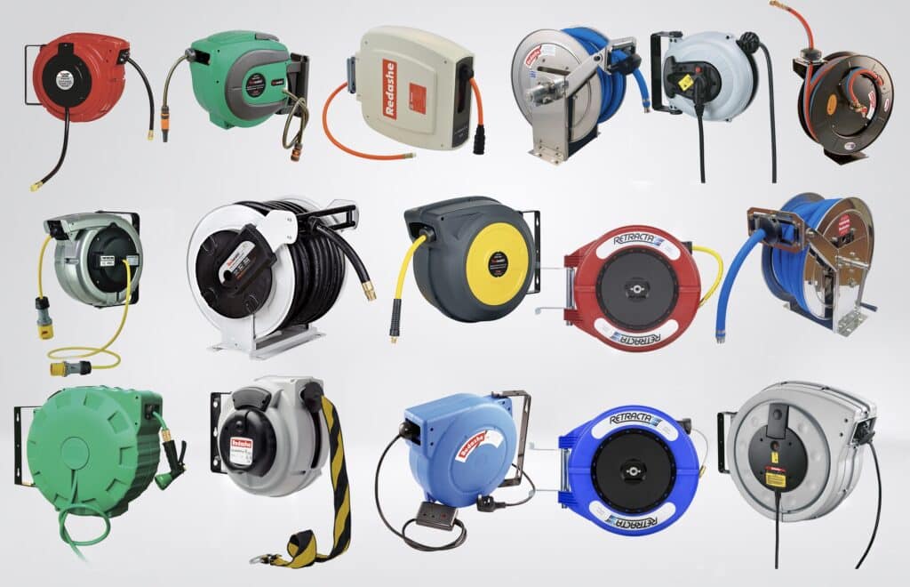
Specify the reel as an assembly. Check hose inside diameter, usable length, working pressure, temperature range, swivel rating, seal compatibility, coupling type, mounting orientation, locking mechanism, retraction force, and expected cycle frequency. Then confirm that the reel doesn’t create unacceptable pressure loss at peak tool demand.
Mount the reel so the hose leaves in the intended direction. A wall-mounted reel pulled sharply sideways can wear the guide and hose cover. A ceiling reel needs enough clearance that the stop ball, coupling, or tool doesn’t strike workers when retracting. Set the stop so the operator can reach it without climbing or pulling on the fitting.
A reel manages two different lengths: stored length and moving length. Stored length affects capacity and pressure drop; moving length affects floor exposure, snagging, and operator reach. Reducing moving length is usually the safety win. Buying the longest reel available can make the system harder to manage.
Test the final installation with the actual tool running. Fully extend the useful length, check retraction from several angles, observe the hose at the guide, and measure pressure at the tool during peak flow. If cycle time changes, review line size and restrictions rather than raising regulator pressure without analysis.
In our experience, this operating test catches reel problems that a static inspection won’t. The tool’s weight changes pull angle, the swivel adds restriction, and the operator may use a different reach than the designer expected. Watch one real work cycle before accepting the installation.
Hose Selection Is an Assembly Decision
ISO 2398:2024 defines 3 types, 3 classes, and 2 categories of textile-reinforced rubber hose for compressed air, with working pressure up to 2.5 MPa and operating temperatures from -40°C to +70°C depending on construction (ISO 2398, 2024). There is no universal pneumatic-hose rating.
Start with the maximum pressure the assembly will actually see, including regulator setting, supply variation, trapped pressure, and credible transients. The safe assembly rating is limited by its lowest-rated hose, fitting, swivel, reel, valve, or accessory. A 20 bar hose doesn’t make a 10 bar coupling suitable for 20 bar service.
Then match the material to the environment and conveyed medium:
| Selection factor | Questions to answer | Common failure if ignored |
|---|---|---|
| Pressure | What are normal, maximum, and transient pressures? | Burst, coupling release, premature fatigue |
| Temperature | What are ambient and air temperatures at the hose? | Hardening, softening, seal damage |
| Chemical exposure | Are oils, cleaners, coolants, ozone, or weld spatter present? | Cover swelling, cracking, loss of strength |
| Flow | What peak flow and acceptable pressure loss are required? | Slow tools, unstable actuators, wasted pressure |
| Motion | Does the hose bend, twist, drag, or flex continuously? | Kinking, torsional fatigue, cover wear |
| Cleanliness | Does the process have air-quality or washdown requirements? | Contamination, corrosion, unsuitable materials |
| Connection | Which thread, coupling profile, and restraint method are used? | Mismatch, leaks, accidental separation |
Thermoplastic hose has its own construction-specific limits. ISO 5774:2023 covers four types of textile-reinforced thermoplastic hose for compressed-air applications in a -10°C to +60°C range (ISO 5774, 2023). That doesn’t make every thermoplastic hose interchangeable; it shows why the product datasheet and marking must be checked.
Minimum bend radius is also product-specific. Parker advises keeping actual bend radius at or above the rated minimum because tighter bends can kink the hose and cause premature failure (Parker Industrial Hose Safety Guide). Avoid generic rules such as four or six times diameter unless the hose manufacturer gives that value.
Line size affects response and energy use. If the hose ID is too small, pressure falls while the tool or actuator consumes air. If it is needlessly large and long, the circuit must fill and vent extra volume. Use the tube ID calculator only as an initial flow-velocity check, then validate pressure drop with the actual hose length, fittings, couplings, and demand.
When connection materials or environments are difficult, the pneumatic fitting selection guide provides a broader compatibility checklist.
How Should Couplings, Isolation, and Whip Protection Be Handled?
For construction work, OSHA 1926.302 requires a safety device at the source or branch for air hoses over 1/2-inch inside diameter, and it requires pneumatic tools to be positively secured to the hose (OSHA 29 CFR 1926.302, current rule). Don’t misapply that construction rule as a universal factory threshold.
In any workplace, the engineering sequence should be consistent: isolate the supply, release stored downstream air, verify zero energy where servicing requires it, and only then disconnect. OSHA 1910.147 addresses control of hazardous energy during servicing and maintenance, including energy that remains stored after shutdown (OSHA 29 CFR 1910.147). Your machine-specific procedure must define the required isolation and verification steps.
Use couplings that match the pressure, flow, media, and connection profile. Pressure-release or vent-before-disconnect couplings can reduce the trapped-air release at the point of separation. CCOHS also recommends attaching the male end to the tool, securing connections, turning the air off before changing tools, and using a safety cable or whip check where appropriate.
A whip restraint doesn’t repair a poor connection. It is a secondary control for the consequence of separation. Verify anchor points, installed length, compatibility, inspection criteria, and whether the restraint can strike nearby workers. For moving tools, place couplings where their mass won’t repeatedly hit the floor or load the hose at a sharp angle.
Never use compressed air to test whether an unknown coupling profile “looks compatible.” Profiles can connect partially, latch incorrectly, or restrict flow. Standardize coupling families by area and label exceptions. Mixed systems deserve a controlled adapter, not an improvised stack of fittings.
What Inspection Findings Require Immediate Hose Removal?
CCOHS’s pneumatic-tool guidance, revised in 2025, says to inspect air hoses regularly for cuts, bulges, and abrasions and to tag and replace defective hose. Parker likewise instructs users to remove damaged, kinked, or cracked hose from service (CCOHS; Parker Safety Guide). A pressure hose isn’t a patch-and-return item.
Stop using the assembly when inspection finds:
- cuts, cracks, exposed reinforcement, blistering, or severe abrasion;
- a kink, flattened section, permanent twist, crushed area, or bend below the rated minimum;
- heat damage, chemical swelling, unusual softening, hardening, or discoloration;
- a loose, corroded, cracked, or visibly shifted fitting or ferrule;
- leaking at the hose wall, coupling, swivel, or crimp;
- damaged strain relief, guard, reel guide, stop, or whip restraint;
- an unreadable identity or pressure marking when traceability is required;
- unknown history after overload, vehicle impact, or coupling separation.
Tag the assembly, isolate it from available stock, and follow the site’s disposition process. Replacement normally means the complete affected assembly, not cutting away damage and installing an unapproved field fitting. If the manufacturer authorizes field assembly, use its specified hose, fittings, tooling, insertion depth, inspection method, and qualification procedure.
Inspection frequency should follow risk. A hose dragged over metal edges each shift needs more frequent checks than a guarded service loop opened twice a year. Use manufacturer instructions, duty cycle, environment, failure history, and legal requirements to set intervals. A calendar alone can’t see abrasion.
In our experience, coupling zones and the first bend beyond a fitting deserve the closest look. That’s where weight, side pull, operator handling, and vibration often combine. Inspect the routing hardware at the same time; a worn guide can damage every replacement hose installed after it.
Leaks matter too, but noise is an unreliable detector in a busy plant. The push-in fitting leak guide explains safer detection and connection checks. Don’t run a hand along a pressurized line to search for a leak.
Labels, Color, and Change Control
ISO 4414 applies to pneumatic systems through design, installation, modification, maintenance, and cleaning, so identification must survive more than the initial build (ISO 4414, 2010). A useful hose label connects the physical assembly to its approved service, pressure class, inspection record, and isolation point.
Labeling should answer practical questions without requiring guesswork:
- What service does this line carry?
- Which machine, zone, or tool does it feed?
- What is the approved pressure or assembly specification?
- Where is the upstream isolation device?
- Who owns inspection and replacement decisions?
- Which coupling family or contamination class applies?
Color can speed recognition, but it should not be the only control. Lighting, dirt, fading, color-vision differences, and locally inconsistent meanings can defeat it. Use text or symbols with a documented site legend, and apply the same convention to drawings, maintenance records, spare assemblies, and isolation points.
Treat a routing change as an engineering change when it affects pressure, flow, movement, guarding, sanitation, or access. Photographing the approved route can help maintenance restore it after service, but the record should also contain the hose specification and connection details. A photo alone can’t show pressure rating or material compatibility.
The replacement unit should be the identified assembly, not an anonymous length of hose. When hose, fittings, swivel, restraint, and route are controlled together, a technician can replace like for like and recognize when a proposed substitute needs review.
How Should a Hose-Management Audit Be Documented?
OSHA 1910.22 requires regular inspection of walking-working surfaces and prompt correction or guarding of hazardous conditions (OSHA 29 CFR 1910.22). A useful pneumatic-hose audit therefore records the defect, location, exposure, interim control, responsible owner, due date, and evidence of closure, not merely a pass or fail box.
Use the same six routing zones from the initial survey. For each hose assembly, record:
- asset, machine, and exact location;
- route type and movement pattern;
- hose and fitting identification;
- working pressure, temperature, media, and flow requirement;
- minimum bend radius and observed tightest bend;
- abrasion, crush, heat, chemical, and traffic exposure;
- coupling, swivel, restraint, and isolation condition;
- inspection result and removal criteria;
- corrective action, owner, and completion date;
- post-correction verification under normal operation.
Prioritize by consequence and exposure. An unknown hose above a guarded, rarely occupied area is different from the same unknown assembly feeding a handheld tool beside a busy aisle. Deal first with active damage, uncontrolled stored energy, floor crossings, vehicle exposure, uncertain pressure ratings, and connections that can separate.
After correction, run the equipment. Watch the complete travel, listen for leaks from a safe position, confirm guards and isolation remain accessible, and verify that the operator doesn’t have to defeat the new routing to perform the task. A route that workers immediately unclip is a design problem worth revisiting.
For a wider plant review, connect hose findings to FRL condition and point-of-use pressure and to the required compressed-air quality class. Wet, dirty, or poorly regulated air can shorten component life even when the floor looks perfectly organized.
Frequently Asked Questions About Pneumatic Hose Management
ISO 2398:2024 recognizes multiple hose types, classes, and categories rather than one universal specification (ISO 2398, 2024). The same principle applies to the questions below: safe routing, replacement, reels, and restraints depend on the assembly, duty, environment, and applicable workplace rules.
How often should pneumatic hoses be inspected?
Set intervals from risk, manufacturer instructions, motion cycles, environment, and failure history. Inspect high-motion, floor-exposed, hot, chemically exposed, or frequently connected assemblies more often. CCOHS calls for regular inspection but doesn’t prescribe one universal monthly or annual schedule, so document a site-specific frequency and shorten it when damage trends appear.
Can a damaged pneumatic hose be repaired?
Remove a cut, cracked, blistered, kinked, crushed, leaking, or fitting-damaged assembly from service. Don’t tape or patch it. Field reassembly is acceptable only when the hose manufacturer provides compatible components, tooling, assembly instructions, and inspection criteria, and when the site has qualified people and an approved procedure.
Are overhead hose reels always safer than floor routing?
No. A correctly located reel can keep unused hose away from a walkway, but excessive retraction force, side pull, poor mounting, an unsuitable swivel, or a hanging coupling can create new hazards. Verify reach, resting position, retraction path, pressure rating, flow, and operator behavior with the actual tool running.
Do all pneumatic hoses need whip checks?
No single rule covers every industrial application. OSHA’s over-1/2-inch safety-device requirement is in its construction-tool standard, while CCOHS recommends safety cables for pneumatic-tool connections. Apply the law governing your workplace, then assess pressure, hose size, coupling type, movement, occupancy, and separation consequence before specifying a restraint.
Should pneumatic hoses be replaced on a fixed calendar?
Not by calendar alone. Hose life depends on pressure cycles, temperature, flexing, torsion, abrasion, chemicals, installation, and storage. Establish a maximum service policy where required, but combine it with condition-based removal criteria and traceable inspection. Replace immediately after disqualifying damage or an event that makes the assembly’s integrity uncertain.
What information should be included when specifying a replacement hose assembly?
Provide hose ID and length, maximum working pressure, temperature, air quality, flow demand, fitting materials, thread and coupling profiles, movement, minimum bend radius, environmental exposure, reel or swivel details, and restraint requirements. Include photos or drawings of connection orientation when routing or fitting angle could change assembly stress.
Final Recommendation
OSHA’s walking-surface rule and ISO 4414’s lifecycle approach point to the same conclusion: pneumatic hose management is a controlled system, not a housekeeping event (OSHA 1910.22; ISO 4414). Start with the 6 routing zones, remove active defects, and then standardize each approved assembly.
The practical order is straightforward: clear walking and vehicle paths, isolate stored energy, verify pressure and material compatibility, control motion and bend radius, standardize couplings, define removal criteria, and document closure. That sequence improves safety without hiding pressure-drop or maintenance problems behind neat-looking trays.
If you need an independent review of a hose route or replacement specification, learn more about our pneumatic engineering experience or send the application details. Include the machine, pressure, hose ID and length, flow demand, movement, environment, connection profiles, and photos of the installed route.