

A custom pneumatic cylinder is an actuator whose geometry, materials, interfaces, sensing, or acceptance requirements are engineered beyond a normal catalog configuration. It should move through controlled engineering gates, not disappear into a supplier’s factory after an RFQ. Specifically, the practical lifecycle is: application definition, specification freeze, drawing approval, manufacturing, inspection and factory acceptance testing, then installation and commissioning.
Importantly, the most expensive mistakes usually occur at the interfaces. For example, a correct bore does not compensate for a wrong mounting datum. Likewise, a passed pressure test does not prove that a long rod is aligned on the machine. A familiar seal material is not automatically suitable for the actual temperature, cleaning chemical, lubricant, or food-contact condition.
Key Takeaways
- Decide whether the job needs a true custom design, a modified catalog cylinder, or an ISO-interchangeable replacement before starting new drawings.
- Freeze loads, pressure, stroke, speed, duty, environment, mounting datums, ports, sensing, and acceptance criteria in one controlled specification.
- Approve the drawing before purchasing material or cutting metal, and record every post-freeze change.
- Put measurable inspection and test requirements in the purchase order; do not rely on a supplier’s undefined “standard test.”
- Treat installation and commissioning as part of cylinder acceptance, with energy isolation, alignment checks, low-speed trials, and a documented baseline.
In other words, the best project file is not the most detailed CAD model. It is the smallest controlled package that lets purchasing, manufacturing, quality, maintenance, and the machine builder answer the same question: what evidence proves this cylinder is acceptable?
Use current standards, manufacturer documentation, and a gate-based project workflow instead of unsupported performance stories or universal test claims.
Key Takeaways
ISO 15552:2018 standardizes mounting dimensions for detachable-mount pneumatic cylinders with bores from 32 mm to 320 mm and rated pressure up to 1,000 kPa (10 bar). That is useful for interchangeability, but it does not replace the application specification, drawing review, acceptance plan, or installation risk assessment (ISO 15552, confirmed current in 2025).
Therefore, use the lifecycle below as a responsibility map:
Specifically, three rules keep the process auditable:
- Requirements must be measurable or explicitly marked as informational.
- Drawing approval must identify the revision being released for manufacture.
- Acceptance must produce records that can be matched to the cylinder serial or batch identity.
When Is a Custom Pneumatic Cylinder Actually Necessary?
A custom cylinder is necessary when the application cannot be met safely or reliably by a catalog product or a controlled modification. Before authorizing a new design, compare envelope, force, stroke, mounting, ports, sensing, environment, and duty against standard options. ISO 15552 provides one interchangeability route across 32-320 mm bores (ISO 15552, 2018).
Use this decision order:
- Standard catalog cylinder: preferred when interfaces and ratings fit without machine changes.
- ISO-interchangeable replacement: useful when the mounting envelope follows an applicable dimensional standard. See our ISO 15552 interchangeability guide.
- Modified standard cylinder: appropriate for controlled changes such as port position, rod end, sensor provision, material, wiper, or special stroke when the base platform remains valid.
- True custom cylinder: justified when load path, envelope, mounting geometry, environment, sensing, or performance cannot be resolved within a proven platform.
However, custom is not automatically better. A unique tube, piston, seal stack, or mount can create future spare-part and lead-time risk. Therefore, ask the supplier to show which parts remain catalog-standard and which become project-specific.
A useful custom-design metric is uniqueness count: the number of parts that cannot be replaced from a controlled standard family. Consequently, lowering that count often improves maintainability without changing the machine interface.
In our experience, the quickest productive custom-cylinder reviews start with the machine interface and the acceptance evidence, not a preferred catalog series. That order exposes missing datums, pressure assumptions, and maintenance constraints before the supplier commits to a design.
What Must Be Frozen Before Design Starts?
Freeze the operating case, interfaces, environment, and acceptance evidence before detailed design. ISO 4414 covers pneumatic-system requirements across assembly, installation, operation, maintenance, and cleaning, while ISO 12100 requires lifecycle hazard identification and risk reduction. The specification therefore needs more than bore, stroke, and nominal pressure (ISO 4414, 2010; ISO 12100, 2010).
Specification capsule: A custom pneumatic cylinder specification is a controlled interface document, not a product wish list. It should define the load and motion cases, minimum pressure available during motion, stroke, speed, duty, mounting datums, rod-end geometry, ports, sensors, environment, and acceptance evidence. ISO 4414 extends pneumatic-system safety across installation, operation, maintenance, and cleaning, while ISO 12100 applies risk assessment across the machine lifecycle. Therefore, design inputs must include access, stored energy, foreseeable misuse, and maintenance conditions as well as nominal performance. The supplier can then convert the requirements into an approved drawing, bill of materials, and test plan. If any interface changes after design freeze, the project should return to documented review rather than relying on a verbal exception (ISO 4414; ISO 12100).
Application and motion data
First, record the moving mass, external force, direction, speed, cycle profile, dwell time, impact risk, side load, and expected annual cycles. In particular, state the available pressure at the cylinder inlet during motion, not only the compressor setting. Include the lowest credible pressure case for force review.
The basic extension-force estimate is:
F_theoretical = P x A
For retraction, subtract the rod area from the piston area. Then account for friction, pressure loss, acceleration, orientation, and a project-specific design margin. For example, the available force during a fast stroke may be lower than a static calculation suggests. For the derivation, see the pneumatic cylinder formula.
Mechanical and pneumatic interfaces
Define all mounting datums, hole patterns, pin sizes, rod-end thread, port thread and position, sensor locations, allowed adjustment, fully retracted length, and clearance through the complete stroke. Add mating-part drawings where a dimension depends on the machine.
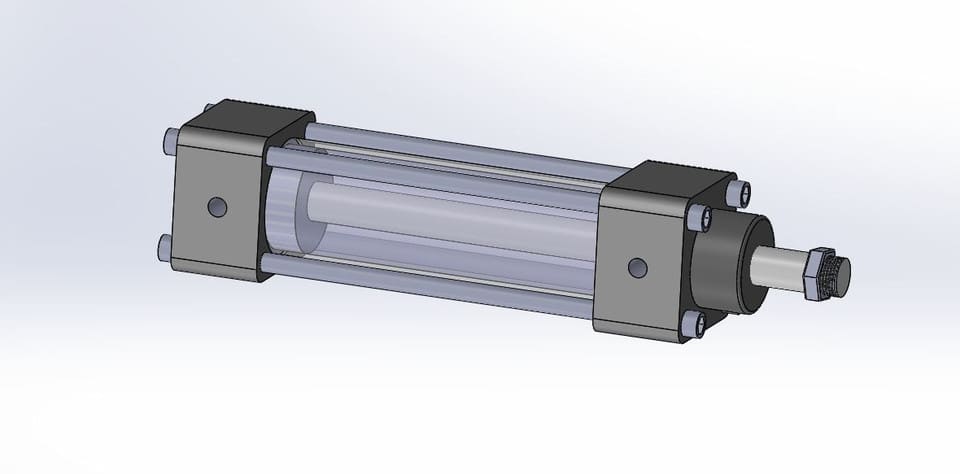
Notably, the retained source image above is now stored locally. It illustrates the right design-review object: the cylinder and its interfaces, not an isolated product photograph.
Environment, materials, and compliance
List ambient and media temperature, humidity, dust, washdown, cleaning chemicals, corrosion exposure, outdoor UV, lubricant policy, and any hygiene constraint. IEC 60529 classifies enclosure protection against ingress, but an IP code alone does not establish chemical compatibility or cleanability (IEC 60529, consolidated edition 2013).
For food-contact applications, avoid the blanket phrase “FDA-approved material.” Specifically, FDA guidance requires reviewing the specific substance, supplier, intended use, and conditions of use. Therefore, request declarations and traceability for the actual components that may contact food (FDA food-contact status guidance, retrieved 2026-07-10).
Seal choice must follow the real temperature, lubricant, surface finish, pressure, and chemical exposure. Our industrial cylinder seal guide explains why a polymer name alone is not a complete selection.
Acceptance and document requirements
Finally, specify which dimensions need recorded results, the leak-test method and limit, operating-pressure range, functional checks, sensor verification, surface or coating requirements, material documents, calibration expectations, labeling, packaging, spare parts, and drawing format. If a requirement is not written before quotation, it is vulnerable to being priced or interpreted differently later.
How Should Drawing Approval and Design Freeze Work?
Drawing approval should release 1 identified revision for manufacture and define how later changes are handled. Festo’s configuration workflow combines cylinder selection, accessories, mounting components, and CAD output, illustrating why the approved assembly matters more than a disconnected part number (Festo Design Tool 3D, retrieved 2026-07-10).
The approval package should include:
A drawing freeze is the documented release of one identified design revision for manufacture. It does not prevent every later change; it ensures that any change returns to technical review, impact assessment, and recorded approval before the supplier acts on it.
- outline drawing with overall and installed dimensions;
- mounting datums, tolerances, pin or bolt details, and rod-end interface;
- bore, stroke, rod diameter, port details, and cushioning method;
- sensor type, switching position, connector, cable exit, and protection;
- material and finish callouts linked to the applicable components;
- bill of materials or controlled specification for critical seals and wear parts;
- inspection and test plan with acceptance limits;
- drawing revision, approval names, date, and change history.
Importantly, do not write “same as sample” unless the sample is identified, measured, and retained under control. A worn sample can reveal the machine envelope, but it cannot prove the original bore, surface finish, seal material, or design pressure.
Use an interface control table
An interface table makes cross-functional review faster:
| Interface | Controlled value | Verified by | Approval owner |
|---|---|---|---|
| Mounting | datums, holes, pins, alignment | drawing + machine check | mechanical engineering |
| Motion | stroke, retracted length, clearance | drawing + motion review | machine builder |
| Pneumatic | ports, pressure, flow, exhaust | schematic + calculation | controls/pneumatics |
| Electrical | sensor, connector, switching point | I/O list + drawing | controls engineering |
| Environment | temperature, chemicals, ingress | material declarations | process/EHS/quality |
| Acceptance | dimensions, leak, function, records | inspection and test plan | quality/owner |
Treat every drawing note as either design intent or acceptance criterion. In other words, if a note cannot be inspected, tested, or verified through controlled documentation, rewrite it until both parties understand how conformity will be judged.
Control post-freeze changes
After approval, a change to material, seal, port, sensor, surface treatment, or tolerance can affect price, lead time, validation, and spare parts. Accordingly, require a deviation request that states the reason, affected drawings, technical impact, and disposition. Verbal approval in a meeting is not a controlled design change.
What Happens During Manufacturing and In-Process Inspection?
Manufacturing converts the approved revision into traceable parts, then verifies the characteristics that cannot be recovered easily after assembly. ISO 10012:2026 focuses measurement management on valid, reliable results across design, production, testing, and service. NIST adds that metrological traceability needs a documented, unbroken calibration chain with stated uncertainty (ISO 10012, 2026; NIST, retrieved 2026-07-10).
Measurement capsule: Measurement traceability and measurement suitability answer different questions. NIST defines traceability through a documented, unbroken chain of calibrations in which each link contributes uncertainty. However, NIST also cautions that traceability alone does not prove that a result is fit for the intended decision. ISO 10012:2026 addresses the wider measurement-management system needed for valid and reliable results in design, production, testing, monitoring, and service. For a custom cylinder, the inspection plan should therefore match the instrument, method, environment, resolution, and uncertainty to the drawing tolerance and functional risk. A calibrated caliper may be suitable for an overall length but unsuitable for a tight bore or geometric tolerance. The record should identify what was measured, how, with which equipment, against which revision, and with what result (NIST; ISO 10012).
For example, a typical route includes material receipt, cutting, tube and end-cap machining, rod manufacture, honing or other bore preparation, surface treatment, cleaning, seal installation, assembly, and test. However, the exact sequence depends on design; it should not be presented as a universal process.
Inspect at the point of control
Some characteristics are best verified before later operations hide them:
| Stage | Examples of controlled characteristics | Evidence |
|---|---|---|
| Incoming material | grade, condition, dimensions, certificate identity | receipt record and supplier document |
| Machining | datums, threads, grooves, concentricity, rod features | in-process measurement record |
| Bore finishing | size, geometry, surface requirement | bore and surface inspection |
| Coating or treatment | type, specified thickness or condition | processor certificate and inspection |
| Assembly | cleanliness, seal orientation, lubricant, torque where specified | traveler/checklist |
| Final test | leak, movement, cushioning, sensors, pressure | serial-linked test report |
Honed tube quality matters because the bore is a running and sealing surface; our guide to honed cylinder tubes explains the function. However, no single tight machining tolerance belongs in every cylinder. Instead, tolerance should follow the drawing, fit, measurement capability, and functional risk.
Match measurement capability to the decision
Calibration status is necessary, but NIST cautions that traceability alone does not prove a result is fit for purpose. Specifically, the instrument range, resolution, uncertainty, method, environment, and operator process must support the tolerance being accepted. A caliper can be calibrated and still be the wrong tool for a tight bore or geometric requirement.
From our work, the most useful inspection records connect three identifiers on one page: the cylinder or batch, the approved drawing revision, and the measuring equipment. That linkage makes a later dimensional question far easier to investigate than a folder of unlabeled readings.
Which Acceptance Tests Belong in the Purchase Order?
The purchase order should name each test, method, condition, limit, sample quantity, and required record. Proof pressure must not be copied from a generic rule: one current SMC CM2/CDM2 catalog example lists 1.0 MPa maximum operating pressure and 1.5 MPa proof pressure, but those values apply to that product family, not every custom cylinder (SMC CM2/CDM2 catalog, p. 11).
Acceptance capsule: A factory acceptance test proves only the requirements, methods, and conditions written into its plan. Therefore, a useful custom-cylinder FAT identifies the product revision, test medium, pressure, stabilization and hold times, leak limit, stroke condition, cushioning setting, sensor checks, sample quantity, witness status, and required records. A proof test is not automatically a life test, and a short cycling check is not evidence of long-term endurance. The SMC CM2/CDM2 catalog illustrates a product-specific relationship between 1.0 MPa maximum operating pressure and 1.5 MPa proof pressure, but that example must not be generalized to another design. The approved cylinder drawing and risk assessment should set the applicable limit. Finally, acceptance records should link results to the serial or batch identity so the delivered unit can be matched to the evidence (SMC CM2/CDM2 catalog, p. 11).
Minimum final-acceptance structure
A factory acceptance test (FAT) is a documented check of the agreed requirements at the supplier’s site before shipment. It is only as strong as its approved methods, limits, test conditions, witness rules, and product identity.
- Identity check: part number, serial or batch, revision, and configuration.
- Dimensional inspection: critical interfaces and any recorded characteristics from the drawing.
- Leak test: medium, pressure, stabilization time, method, limit, and temperature.
- Pressure test: design-approved pressure, hold time, safe fixture, and acceptance condition.
- Functional stroke test: full travel, free movement, cushioning, speed-control direction, and abnormal noise.
- Sensor test: switching positions, repeatability expectation, connector, and output type.
- Documentation review: drawing, inspection report, material or process documents, test record, and manuals.
Do not require helium leak testing or a fixed cycle count unless the application risk and test plan justify them. Helium is one possible method; alternatively, pressure-decay, flow, bubble, vacuum, or other methods may be appropriate depending on the specified limit and test object. Likewise, a short functional cycle test is not a life test.
Define witness and hold points
For a critical or first-article cylinder, distinguish:
- Review point: supplier proceeds after submitting a record.
- Witness point: customer may observe, but the supplier can proceed after the agreed notice period.
- Hold point: supplier cannot proceed without written release.
Put hold points only where failure would be expensive to reverse, such as drawing release, hidden interface inspection, or destructive material verification. Conversely, too many hold points create delay without improving evidence.
Installation and Commissioning Checklist
Installation is the sixth engineering gate, not a logistics step. OSHA 29 CFR 1910.147 explicitly includes pneumatic energy and requires control of stored or residual energy before servicing. Parker guidance also calls for checking cylinder alignment in extended and retracted positions, because misalignment can load the rod, bearings, seals, and mount (OSHA 1910.147; Parker installation guidance, retrieved 2026-07-10).
Installation capsule: Notably, a cylinder can pass dimensional, leak, pressure, and functional checks at the factory yet still be unacceptable on the machine. Installation introduces the actual brackets, pins, load path, tubing, controls, guarding, and motion envelope. OSHA’s hazardous-energy rule includes pneumatic and stored energy, so the site procedure must isolate and verify energy before hands enter the hazard zone. Parker also advises checking alignment in both the extended and retracted positions. Therefore, commissioning should begin with identity and damage checks, followed by safe low-energy motion, full-stroke clearance, sensor verification, and progressive adjustment of speed and cushioning. The final baseline should record pressure during motion, cycle time, settings, and observed leakage so maintenance can compare future behavior against an accepted condition (OSHA 1910.147; Parker).
Before mounting
- Match part number, revision, port orientation, sensor configuration, and accessories to the approved drawing.
- Inspect shipping protection, rod surface, threads, ports, and seals for visible damage or contamination.
- Confirm the machine is in a safe state and follow the site’s energy-control procedure.
- Clean mating surfaces and verify that brackets, pins, fasteners, and alignment features are correct.
- Check that tubing, fittings, flow controls, and silencers match the schematic and expected flow.
During mechanical installation
- Support the cylinder so its weight does not bend the rod or distort the mount during assembly.
- Tighten fasteners using the approved machine or component procedure.
- Align fixed mounts without forcing the cylinder into position.
- Align pivot pins and allow the intended articulation; do not create a second rigid constraint.
- Check clearance at both end positions and through the path, including tubing and sensor cables.
- For long strokes or compressive loads, review rod buckling and external guidance rather than using the cylinder rod as a machine guide.
For more on machine-side load control, see how pneumatic cylinders work in automation.
Pneumatic and electrical connection
Verify port identity before connecting tubing. Keep contaminants out of open ports, use compatible thread sealing practices, and prevent sealant from entering the flow path. Mount flow controls in the intended direction and confirm sensor voltage, output type, connector pinout, and PLC logic.
Controlled first motion
- Isolate personnel from the motion envelope.
- Start at reduced pressure or reduced flow where the design and site procedure allow it.
- Jog through a short motion and confirm direction.
- Extend and retract slowly while checking binding, clearance, tubing, and sensor switching.
- Adjust cushioning and speed progressively; do not use the end cap as a repeated hard stop.
- Bring the machine to normal pressure and load only after the low-energy checks pass.
- Inspect for external leakage, abnormal sound, heat, impact, or mount movement.
Finally, record the commissioning baseline: point-of-use pressure during motion, cycle time, sensor positions, speed-control settings, cushioning settings, and leak-check result. As a result, maintenance has a factual comparison when performance changes. See our pneumatic cylinder maintenance comparison for ongoing checks.
Our team found that commissioning notes become much more useful when they record settings and conditions rather than only “passed.” A future technician can compare pressure, time, sensors, flow controls, and cushioning against that baseline before removing the cylinder.
What Documents and Spare Parts Should Ship with the Cylinder?
The 10 document classes below let maintenance identify, isolate, inspect, and rebuild the cylinder without reconstructing the project history. ISO 4414 addresses installation, operation, maintenance, and cleaning across the pneumatic-system lifecycle; the supplier package should support those activities with controlled information, not only a commercial packing list (ISO 4414, 2010).
Handover capsule: A custom cylinder handover package preserves the engineering baseline after the project team moves on. At minimum, it should identify the final drawing revision, cylinder serial or batch, inspection and test records, installation instructions, sensor details, and approved spare parts. Add material, coating, food-contact, or calibration documentation when the specification requires it. ISO 4414 treats installation, operation, maintenance, and cleaning as lifecycle concerns, so service information should explain safe isolation, adjustment, inspection, and approved repair boundaries. A spare-parts list should distinguish standard wear parts from project-specific rods, tubes, pistons, end caps, brackets, and sensors. That distinction helps maintenance choose between a seal kit, a controlled rebuild, and a complete spare cylinder without relying on an unsupported fixed service-life promise (ISO 4414, 2010).
Request the following as applicable:
- approved outline and assembly drawing with final revision;
- cylinder part number, serial or batch identity, and nameplate data;
- inspection and factory test records linked to that identity;
- material, coating, or food-contact documentation required by the specification;
- installation, operation, adjustment, and safety instructions;
- recommended spare-parts list with seal-kit and wear-part identifiers;
- exploded view or service drawing when field rebuild is permitted;
- sensor documentation and connector pinout;
- storage, preservation, and shelf-life guidance for spare seals;
- deviation and change records closed before shipment.
Spare strategy should follow downtime risk, not a universal rebuild-life claim. For example, a custom rod, end cap, tube, piston, or sensor bracket may justify a complete spare cylinder. Alternatively, if the design uses standard wear parts, a seal kit plus a controlled repair drawing may be sufficient. Confirm which repairs require supplier facilities and which are approved for site maintenance.
FAQs About Custom Pneumatic Cylinder Projects
ISO 15552 covers one standardized family from 32 mm to 320 mm bore, yet many custom projects exist because envelope, load path, environment, sensing, or documentation falls outside a catalog solution. The answers below focus on decisions that should be frozen before manufacture rather than universal price or lead-time promises (ISO 15552, 2018).
How long does a custom pneumatic cylinder take to manufacture?
There is no defensible universal lead time. Timing depends on drawing cycles, material availability, unique tooling, outside processing, inspection, testing, and customer hold points. Ask for a dated milestone plan covering specification freeze, drawing approval, material release, manufacture, FAT, documents, and shipment; start the clock from an explicitly defined gate.
What information is required for an accurate custom-cylinder quotation?
Provide force and load cases, available pressure during motion, stroke, speed, duty, mounting datums, envelope, rod-end and port details, sensing, temperature, contaminants, cleaning chemicals, life expectations, and acceptance records. ISO 4414 spans installation through maintenance, which is why a quote based only on bore and stroke is incomplete (ISO 4414, 2010).
Should every custom cylinder be proof-tested at one and a half times working pressure?
No universal rule in this guide supports that claim. The SMC CM2/CDM2 example uses 1.0 MPa maximum operating and 1.5 MPa proof pressure, but another design may use different approved values and methods. Put the exact pressure, medium, hold time, fixture, safety controls, and acceptance criteria on the test plan (SMC catalog, p. 11).
Can a custom pneumatic cylinder be rebuilt?
Often yes, but rebuildability must be designed and documented. Confirm replaceable seals and bearings, disassembly method, rod and bore inspection limits, torque or retention requirements, test procedure, and spare-part availability. Do not promise a fixed service-life extension; life depends on cycles, load, alignment, contamination, lubrication, pressure, temperature, and maintenance quality.
Does a custom cylinder always carry a fixed price premium?
A fixed percentage premium is not reliable. Cost is driven by engineering time, one-off components, material, machining, treatments, tooling, inspection, test documentation, quantity, and future spares. Therefore, compare total installed risk: machine changes, qualification effort, downtime exposure, energy use, maintainability, and replacement availability, not purchase price alone.
What is the most important installation check?
After safe energy isolation, verify alignment and freedom of movement through the full stroke. Parker specifically advises checking alignment in extended and retracted positions. A cylinder that passes factory tests can still fail early when the machine imposes side load, binding, impact, or a rigidly over-constrained mount (Parker).
Sources and Retrieval Notes
The 13 source entries below support defined claims; they do not certify an individual custom design. ISO 15552 is the dimensional-interchangeability reference, while ISO 4414 and ISO 12100 cover system safety and lifecycle risk. All web sources were checked on 2026-07-10 unless another confirmation date is stated (ISO 15552).
- ISO 15552:2018, Pneumatic fluid power cylinders with detachable mountings, dimensional interchangeability, 32-320 mm bores, and rated pressure up to 1,000 kPa. Confirmed current in 2025.
- ISO 4414:2010, General rules and safety requirements for pneumatic systems, lifecycle safety covering design through installation, operation, maintenance, and cleaning. Confirmed current in 2021.
- ISO 12100:2010, Risk assessment and risk reduction, machine-lifecycle hazard identification, risk assessment, and documentation. Confirmed current in 2022; revision work is indicated by ISO.
- ISO 10012:2026, Quality management requirements for measurement management systems, validity and reliability of measurement results in design, production, testing, monitoring, and service.
- NIST: Metrological Traceability, documented unbroken calibration chain, measurement uncertainty, and fitness-for-purpose caution.
- OSHA 29 CFR 1910.147, control of hazardous energy, including pneumatic and stored energy.
- FDA: Determining the Regulatory Status of Components of a Food Contact Material, substance-, supplier-, use-, and condition-specific status.
- IEC 60529, enclosure ingress-protection classification.
- Parker Pneumatic Products Catalog 0900P, cylinder selection, mounting, application considerations, and custom modifications.
- Parker Cylinder Safety and Installation Guidance, alignment, pivot mounts, installation, maintenance, and modification cautions.
- SMC CM2/CDM2-Z Catalog, product-specific operating and proof pressure example on page 11.
- Festo Design Tool 3D, configured cylinder, accessory, mounting, sensor, and CAD workflow.
- AutomationDirect: How to Select a Pneumatic Cylinder, short video covering early cylinder selection inputs.