

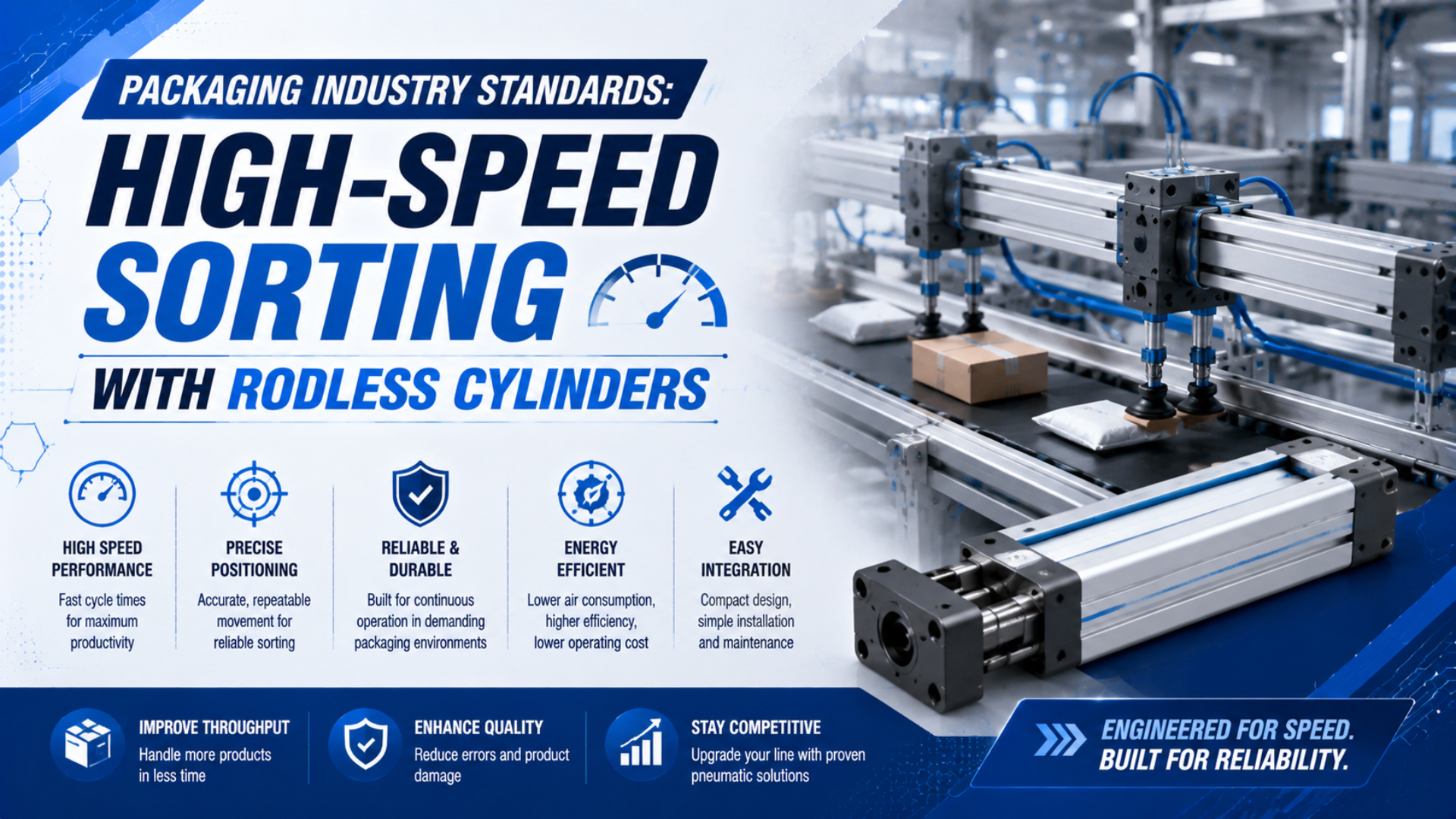
High-speed sorting with rodless cylinders is not governed by one standard that assigns every actuator a minimum cycle rate, ±0.1 mm repeatability, or a universal service life. Standards govern different parts of the machine. ANSI/PMMI B155.1 addresses packaging and processing machinery safety, ISO 12100 supplies a risk-assessment method, ISO 4414 covers pneumatic-system hazards, and ISO 13849-1 applies when a control function reduces risk.
The cylinder’s acceptable speed, load, guide moment, stopping energy, and repeatability still come from the exact model, its catalog conditions, and the machine’s own acceptance specification. For a high-speed sorter, the practical task is to convert those sources into measurable FAT and SAT checks.
Key Takeaways
- ISO 15552 does not define rodless-cylinder sorting performance.
- Packages per minute and actuator cycles per minute are different requirements.
- Peak cushion-entry speed can exceed average stroke speed.
- Guide moments and stopping energy require model-specific checks.
- FAT/SAT limits must be written before tuning begins.
The standards-to-test boundary matters. A machine may use standards-compliant components and still miss products, rebound at the stop, lose dynamic pressure, or move unexpectedly after a fault. Compliance establishes the design process and safety framework; application validation establishes whether the installed axis performs its assigned sorting duty.
From our analysis of the four standards and two manufacturer catalogs cited below, three boundaries must remain separate: machinery safety requirements, pneumatic-system requirements, and model-specific actuator limits. Combining them into one “industry standard” number hides which document supports each acceptance criterion.
Standards That Apply to a High-Speed Packaging Sorter
ANSI/PMMI B155.1-2023 covers new, modified, or rebuilt packaging machinery, including conveying machinery within packaging functions. ISO 4414:2010 covers pneumatic-system hazards on machinery. Neither publishes a universal rodless-cylinder speed, repeatability, side-load percentage, or cycle-life target (PMMI; ISO 4414).
Use the standards as a hierarchy rather than as interchangeable product certificates:
ANSI/PMMI B155.1 is a packaging- and processing-machinery safety standard for machinery in its stated scope. ISO 4414 is a pneumatic-system safety standard. ISO 15552 is a dimensional interchangeability standard for the rod-cylinder series described in its scope.
| Layer | Relevant document | What it contributes | What it does not provide |
|---|---|---|---|
| Packaging machine | ANSI/PMMI B155.1-2023 for applicable North American machinery | Responsibilities, documented risk assessment, and risk reduction for packaging and processing machinery | A rodless-cylinder performance rating |
| Machinery risk assessment | ISO 12100:2010 | Hazard identification, risk estimation, risk evaluation, risk reduction, documentation, and verification | A required cylinder bore, speed, or stop method |
| Pneumatic system | ISO 4414:2010 | General rules and safety requirements for pneumatic systems and components used on machinery | A default sorting throughput or positioning tolerance |
| Safety-related control | ISO 13849-1:2023, when applicable | Methodology for designing and integrating safety-related parts of control systems | The required safety function or performance level for a particular sorter |
| Cylinder dimensions | ISO 15552:2018 | Interchangeability dimensions for specified single- or double-rod cylinders with detachable mountings | Rodless-cylinder dimensions, sorting accuracy, or high-speed endurance |
ISO 15552:2018 explicitly covers single- or double-rod pneumatic cylinders in its stated dimensional series. Citing it as proof that a mechanically jointed or magnetically coupled rodless cylinder meets high-speed sorting requirements is a category error.
Standards also do not make every listed requirement applicable everywhere. ATEX is relevant when equipment is intended for use in a potentially explosive atmosphere. Food-contact rules matter when a material can reasonably contact food under its intended use. The machine’s market, product, environment, access, cleaning method, and risk assessment determine the applicable set.
What Duty Data Must Be Frozen Before Selecting the Rodless Cylinder?
Parker states that OSP-P selection depends on permissible loads, forces, moments, and pneumatic end-cushion performance; moving mass and piston speed at the start of cushioning are primary inputs. That model-specific approach is more defensible than selecting from a generic “high-speed” label (Parker OSP-P catalog).
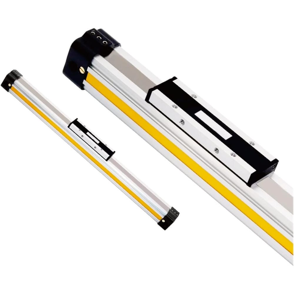
Freeze one worst-case duty profile before comparing cylinders:
From our analysis of the cited catalog procedures, the inputs most easily omitted are cushion-entry speed, the carriage’s own mass, cable and hose forces, center-of-gravity offsets, and the effective stop distance. Each can change the selection even when bore, stroke, and nominal pressure stay unchanged.
| Input | Record this value | Why the sorter needs it |
|---|---|---|
| Product rate | Products per minute for each recipe | Defines the available decision interval, not automatically the actuator cycle rate |
| Product pitch | Minimum time and distance between products | Determines how late a diverter can move without touching the next product |
| Sorting sequence | Home-to-sort, dwell, return, and skipped cycles | Converts line rate into actual actuator motion |
| Stroke | Required useful travel plus stop and adjustment allowance | Sets chamber volume, average motion time, and machine envelope |
| Moving mass | Carriage, tooling, fasteners, product, cable carrier, hoses, and attachments | Drives acceleration force and stopping energy |
| Load geometry | Center-of-gravity offsets in every relevant axis | Produces static and dynamic guide moments |
| Orientation | Horizontal, vertical, inclined, or moving base | Changes assisting or opposing forces and fault behavior |
| Dynamic pressure | Pressure at the actuator port during the worst stroke | Reveals losses hidden by a static regulator reading |
| Environment | Temperature, dust, water, cleaning chemicals, and atmosphere classification | Controls material, seal, ingress, and certification requirements |
| Safe state | Required behavior after guard opening, emergency stop, air loss, power loss, or jam | Defines valves, stored-energy controls, brakes, locks, and restart logic |
The line’s fastest recipe may not be the worst case. A slower but heavier package can create more stopping energy. A lighter product with a smaller pitch may leave less time for the return stroke. A warm machine after several hours can also behave differently from a cold FAT demonstration.
For the broader cylinder specification workflow, use the high-speed pneumatic-cylinder checklist. Service-life claims belong in a separate high-cycle evidence review.
How Do You Convert Package Throughput Into an Actuator Timing Budget?
Parker’s OSP-P catalog says cushion-entry piston speed is typically about 50% higher than average stroke speed. Therefore, stroke divided by travel time cannot approve cushioning. The timing budget must separate detection, logic, valve response, motion, deceleration, dwell, and return (Parker).
Start with the time between products:
Product interval is the time between successive products at the reference sensor or decision point. Actuator cycle time is the time required for the complete commanded motion sequence. They are equal only when the control sequence requires exactly one complete actuator cycle per product.
Here, is seconds per product and is products per minute. At an illustrative rate of 180 products per minute, the interval is 0.333 seconds. That arithmetic does not prove that the actuator must complete 180 full cycles per minute. The PLC sequence may hold one position for several products or move only when a reject appears.
For a product that requires one sorting move and a return before the next conflicting product, write the full budget:
Each term must have a measurable boundary. Detection includes sensor response and filtering. Logic includes task timing and network delay. Valve time includes electrical and pneumatic response. Travel includes acceleration and deceleration rather than assuming constant speed. Margin covers declared variation, not an unexplained percentage copied from another machine.
Measure the signals on a common time base. A useful trace includes the product sensor, PLC decision, valve command, actuator-port pressures, carriage position or end sensor, and reject confirmation. Without synchronized timing, a late sort can be blamed on the cylinder even when the delay began at the photoeye, controller, valve, tube, or exhaust path.
The Cylinder Flow Requirement Calculator can screen bore, stroke, pressure, and target stroke time. Treat its result as valve and tubing pre-selection, then confirm dynamic pressure and actual travel time on the installed machine.
How Should Guide Loads and Stopping Energy Be Checked?
SMC’s MY1 material requires load and moment checks at the relevant piston speed. For specified MY1B conditions at 1,000 to 1,500 mm/s, it recommends an external shock absorber. This is model- and size-specific guidance, not a universal threshold for all rodless cylinders (SMC).
A carriage load creates more than axial force. Its center-of-gravity offsets create pitch, yaw, and roll moments. Acceleration, deceleration, hose drag, cable-carrier force, product impact, and frame deflection can increase those reactions. Check the selected series’ coordinate system and combined-load method; do not convert a permissible load from one axis into a blanket “side load percentage.”
Use kinetic energy as an initial stop screen:
Cushion-entry speed is the piston or carriage speed when deceleration begins inside the selected cushion or external stop. It can be materially higher than average stroke speed, so it should be measured or estimated with the manufacturer’s stated selection method.
Here, is kinetic energy in joules, is the total moving mass in kilograms, and is the speed at cushion entry in metres per second. Because energy varies with the square of speed, doubling produces four times the kinetic energy at the same mass.
The stop may also need to absorb pneumatic drive work during the cushion stroke:
Here, is the effective force continuing to drive the carriage during deceleration, and is the effective stopping distance. This is a screening relationship, not a replacement for the manufacturer’s allowable-energy chart. Use the exact catalog procedure, include gravity where relevant, and apply the specified load factors or derating rules.
Do not assume that a flow control is an energy absorber. It can change speed, but the cushion, shock absorber, stop, mounting, and structure still receive the deceleration load. Rebound, end-cap impact, loosening fasteners, guide play, and sensor chatter are signs that the stop architecture needs review.
The moving-load kinetic-energy guide explains the basic calculation. Use the Cylinder Cushion Energy Calculator as a screening aid, then compare its inputs and result with the selected model’s published limits.
What Does Sorting Accuracy Mean for a Pneumatic Axis?
ISO 13849-1:2023 supplies a methodology for safety-related control-system design, but it does not assign a positioning tolerance or required performance level to a particular sorter. Sorting acceptance must separately define product detection, decision timing, carriage endpoint, mechanical stop behavior, and confirmed product destination (ISO 13849-1:2023).
Do not collapse these measurements into one “accuracy” number:
- Detection repeatability: variation in the product sensor’s switching position or timestamp.
- Command latency: time from detection to the valve output command.
- Motion repeatability: variation in carriage arrival time and position from the same approach direction.
- Endpoint definition: the component that physically sets the position, such as a stop, cushion, lock, brake, or controlled servo-pneumatic loop.
- Sort result: whether the correct product reaches the correct destination without contact damage, miss, double-sort, or interference with the next product.
A reed or solid-state switch normally reports that a magnetic target entered its sensing zone. It does not, by itself, create an exact mechanical position. Intermediate programmable positions require a suitable feedback and control architecture; a standard directional valve plus two end switches is usually an end-to-end motion system.
Write separate tolerances for arrival time, endpoint position, rebound, settling time, and wrong-sort outcome. Then state the measurement location, sensor resolution, sampling method, approach direction, load, pressure, temperature, and recipe. The repeatability-versus-accuracy guide provides the terminology needed for that specification.
FAT and SAT Evidence for the Sorting Axis
ANSI/PMMI B155.1-2023 guides packaging-machinery suppliers and users through a formal, documented risk-assessment process. FAT and SAT should turn the resulting requirements into observable pass/fail evidence under declared conditions, rather than demonstrate only a short nominal-speed run with an unloaded, cold machine (PMMI).
A useful acceptance matrix crosses operating conditions with failure modes. One column says what the machine is doing; another says what is measured; a third contains the project-specific limit and evidence record.
From our analysis of these requirements, one nominal-speed demonstration cannot establish the complete release case. The test set must cover the declared mechanical extremes, dynamic pressure, warm condition, relevant environmental exposure, and risk-assessed faults while preserving the tested hardware and software configuration.
| Test condition | Measurements to record | Acceptance rule to define before the test |
|---|---|---|
| Nominal recipe | Product rate, arrival time, endpoint, pressure, and sort result | Required output and timing distribution |
| Fastest recipe | Minimum product interval and complete move-return budget | No timing conflict with the next product |
| Maximum declared moving mass | Peak or cushion-entry speed, rebound, stop condition, and guide reaction evidence | Inside the exact model’s load, moment, and energy limits |
| Minimum declared dynamic pressure | Port pressure during acceleration, travel time, and end-state confirmation | Completes the safe motion without raising the regulator after the test |
| Warm continuous operation | Timing drift, temperature observations, leakage, guide play, and stop behavior | Remains inside the same acceptance limits after thermal stabilization |
| Jam or blocked product | Product contact, overload response, trapped energy, and recovery sequence | No uncontrolled motion or unsafe automatic restart |
| Product-sensor fault | Diagnostic response, inhibited outputs, and fault indication | Matches the risk-assessed fault behavior |
| Loss and restoration of air or power | Carriage behavior, retained load, stored energy, and restart command | Reaches or maintains the defined safe state; no unexpected restart |
| Guard or emergency-stop demand | Stop response and residual pneumatic motion | Matches the validated safety-function specification |
| Cleaning or environmental exposure | Seal, corrosion, sensor, cable, lubricant, and ingress condition | Matches the declared product and installation ratings |
Do not invent one universal sample count for every machine. Set the number of cycles, allowed misses, confidence method, warm-up period, recipes, and fault repetitions in the acceptance plan. A safety-function validation and a production-capability study answer different questions and can require different evidence.
Save raw traces and configuration data with the report: cylinder part number, valve and coil, tube sizes and lengths, flow-control settings, supply and port-pressure locations, sensor part numbers, PLC revision, recipe, payload, ambient condition, and test date. A pass result without the tested configuration is difficult to reproduce after maintenance.
How Do Food, Washdown, and Explosive Environments Change the Specification?
FDA states that the regulatory status of a food-contact article depends on its constituent substances, applicable authorization, manufacturer, and intended conditions of use. A generic “FDA-compliant cylinder” statement is therefore insufficient when seals, grease, coatings, or other materials can reasonably contact food (FDA).
Define the exposure boundary first:
- If the actuator is outside the product and splash zones, document how guards, covers, drainage, and cleaning prevent migration or contamination.
- If a material can contact food, request traceable evidence for its exact intended use and conditions, not a general seal-material label.
- For washdown, verify the complete installed assembly: actuator, switches, connectors, cable entries, fittings, fasteners, covers, drainage, lubricant, and cleaning-chemical compatibility.
- Treat an IP rating as a rating for the exact rated product or enclosure under its stated test conditions. Do not transfer a sensor’s rating to the entire mechanical installation.
- For clean production, verify particle, grease, exhaust, material, cleaning, and packaging data for the exact model. A room classification does not certify the actuator.
ATEX Directive 2014/34/EU covers equipment and protective systems intended for use in potentially explosive atmospheres. It is relevant only after the atmosphere, zone, gas or dust group, temperature class, equipment category, and market requirements have been established (European Commission).
Dust also affects ordinary non-ATEX machines. Powder can enter guides, obscure sensors, clog exhaust silencers, and change friction. Wet cleaning can wash away incompatible grease or drive chemistry into sealing interfaces. These conditions belong in the duty sheet and acceptance test, not in a generic “harsh environment” checkbox.
RFQ and Engineering Release Package
Parker’s OSP-P method bases selection on permissible loads, forces, moments, and cushion performance, including moving mass and speed at cushion entry. An RFQ that lists only bore and stroke omits the variables most likely to invalidate a high-speed sorting application (Parker OSP-P catalog).
Send the supplier and machine integrator:
- Full sorting sequence for every relevant recipe.
- Product rate, minimum pitch, and required decision window.
- Stroke, orientation, mounting, available envelope, and intermediate supports.
- Total moving mass, including carriage, tooling, cables, hoses, and product.
- Center-of-gravity offsets and external forces in the supplier’s coordinate system.
- Target average speed, measured or estimated cushion-entry speed, acceleration, and deceleration.
- Required endpoint, arrival-time, rebound, and settling tolerances.
- Available static pressure and minimum dynamic pressure at the actuator.
- Valve, port, fitting, tube, muffler, and flow-control details.
- Internal cushion, external shock absorber, brake, lock, and mechanical-stop arrangement.
- Product sensors, cylinder sensors, feedback device, controller, and diagnostic coverage.
- Safe-state behavior for guards, emergency stop, air loss, power loss, jam, and restart.
- Temperature, dust, water, chemicals, food-contact boundary, and hazardous-area classification.
- Expected annual cycles and travel, with the exact definition of one cycle.
- FAT/SAT conditions, pass/fail limits, records, maintenance state, and change-control requirements.
For long-stroke flow and support calculations, use the rodless-cylinder conveyor sizing guide. For alignment and guide binding, use the guide-rail parallelism tolerance guide.
What Is the Practical Selection Rule?
ISO 12100 requires documented risk assessment and risk reduction; ISO 4414 addresses pneumatic-system hazards. Approve the rodless axis only when its exact model limits and FAT/SAT results cover the declared recipes, loads, environments, faults, and safe states (ISO 12100; ISO 4414).
Do not buy “2 m/s,” “50 million cycles,” or “±0.1 mm” as isolated labels. Buy a traceable configuration with a defined duty, published model limits, an agreed test method, and measured evidence. If the machine changes product pitch, payload, guide geometry, stop method, valve, tubing, pressure, software, or environment, review whether the original validation still applies.
The strongest packaging sorter is not the axis with the largest headline number. It is the axis whose timing, load path, stopping energy, controls, environmental suitability, and fault behavior remain inside documented limits at the machine’s worst declared operating condition.
High-Speed Rodless-Cylinder Sorting FAQs
ISO 15552 covers specified rod-cylinder interchangeability dimensions, while ISO 4414 covers pneumatic-system safety and PMMI B155.1 addresses packaging machinery in its scope. These distinctions answer the most common questions about speed, accuracy, food applications, cushioning, and acceptance evidence without inventing universal rodless-cylinder limits (ISO; PMMI).
Does ISO 15552 certify a rodless cylinder for high-speed packaging?
No. ISO 15552:2018 establishes interchangeability dimensions for specified single- or double-rod pneumatic cylinders with detachable mountings. It does not certify rodless-cylinder speed, guide capacity, repeatability, cushioning, or service life. Check the exact rodless model’s catalog and validate the installed sorting duty separately.
Is packages per minute the same as cylinder cycles per minute?
Not necessarily. A sorter may hold one position across several products, move only for rejects, or require a move and return within one product interval. Convert the product sequence into detection, command, valve, motion, dwell, and return times before specifying actuator frequency or flow.
Can a magnetic switch guarantee ±0.1 mm sorting accuracy?
Not by itself. A cylinder switch normally indicates that a magnetic target entered its sensing zone. Endpoint accuracy also depends on the guide, mechanical stop, cushion, load, approach direction, pressure, speed, mounting, and measurement method. Specify switch repeatability separately from carriage position and final sort outcome.
When does a high-speed rodless cylinder need an external shock absorber?
Use the selected manufacturer’s mass-speed, load-moment, and cushion-energy procedure. An external shock absorber is needed when the internal cushion cannot absorb the declared moving mass and drive energy, or when the stop architecture requires tighter rebound control. Install it near the load’s effective center of gravity when the catalog requires.
What evidence should FAT and SAT retain?
Retain synchronized timing and pressure traces, position or end-state records, sort results, tested recipes, payload, cylinder and valve part numbers, tube details, flow-control settings, software revision, environmental condition, fault-test results, and the signed acceptance limits. These records make the result reproducible after maintenance or modification.
Sources and technical references
- ANSI/PMMI B155.1-2023. Safety requirements and risk assessment for packaging and processing machinery in its stated scope. PMMI standards page. Retrieved July 26, 2026.
- ISO 12100:2010. Safety of machinery, risk assessment and risk reduction. ISO official page. Retrieved July 26, 2026.
- ISO 4414:2010. General rules and safety requirements for pneumatic fluid-power systems and components. ISO official page. Retrieved July 26, 2026.
- ISO 13849-1:2023. General principles for safety-related parts of control systems. ISO official page. Retrieved July 26, 2026.
- ISO 15552:2018. Dimensional series for specified single- or double-rod pneumatic cylinders with detachable mountings. ISO official page. Retrieved July 26, 2026.
- Parker OSP-P Catalog 0980. Rodless-cylinder loads, moments, cushioning, and cushion-entry speed guidance. Parker official PDF. Retrieved July 26, 2026.
- SMC MY1B Catalog. Model-specific allowable load, moment, speed, and shock-absorber selection guidance. SMC official PDF. Retrieved July 26, 2026.
- FDA Food Contact Materials. Regulatory status of components, authorizations, manufacturers, and intended conditions of use. FDA official guidance. Retrieved July 26, 2026.
- European Commission ATEX. Equipment and protective systems intended for use in potentially explosive atmospheres. European Commission. Retrieved July 26, 2026.