

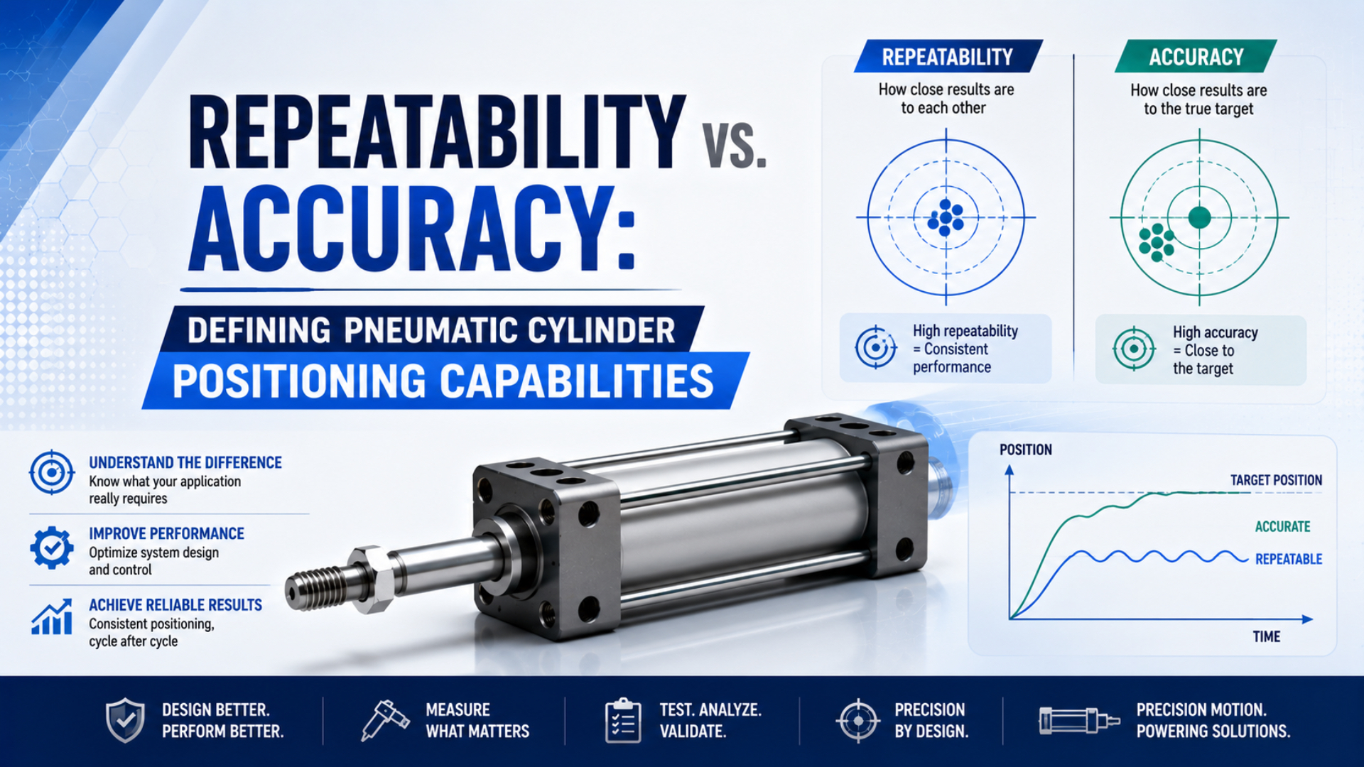
Pneumatic cylinder positioning repeatability describes how tightly an actuator returns to the same measured position under stated conditions. Accuracy asks whether that result agrees with a reference target. They are related, but neither term is useful without the stop method, approach direction, load, speed, air conditions, measurement system, and acceptance limit.
Catalog numbers show why the conditions matter. Festo lists ±0.05 mm repetition accuracy for its DLGF-KF guided rodless drive, while Enfield lists typical positional accuracy of ±0.1% to 1% of full scale for its S2 servo-pneumatic positioning system. Those figures describe different products, architectures, and test boundaries (Festo DLGF, 2025; Enfield S2, accessed 2026).
Key Takeaways
- Specify signed position error and repeatability separately.
- A 0.01 mm sensor resolution does not guarantee 0.01 mm cylinder positioning.
- End-stop and mid-stroke motion require different tests and hardware.
- Catalog values apply only to exact models and stated conditions.
The most useful specification is not “high accuracy.” It is a testable sentence: the measured tooling datum must enter a defined tolerance band after a defined approach, with the production load, speed, pressure range, settling time, and number of cycles recorded.
What Do Repeatability and Accuracy Mean for a Pneumatic Cylinder?
NIST TN 1297 identifies 5 repeatability conditions: the same procedure, observer, instrument, location, and a short measurement interval. It defines accuracy as agreement with the measurand and repeatability as agreement among successive results under those conditions. For a cylinder, the measurand should be the actual tooling or carriage datum, not merely a sensor LED (NIST TN 1297, accessed 2026).
Repeatability is the dispersion of repeated position results under stated, unchanged conditions. Signed position error is the mean result minus a calibrated reference position. Reporting both values keeps random scatter separate from a correctable offset.
In formal metrology, accuracy is qualitative. A machine acceptance document should therefore attach numbers to clearer quantities:
| Term | Practical meaning for a pneumatic axis | Suitable reported value |
|---|---|---|
| Reference position | Calibrated target for the measured tooling datum | in mm |
| Signed position error | Mean measured position minus the reference | in mm |
| Repeatability | Short-term scatter under unchanged conditions | Standard deviation , range, or a defined coverage interval |
| Resolution | Smallest change the sensor or controller reports | Encoder counts, volts, or mm per count |
| Linearity error | Maximum sensor-output deviation from its reference line | mm or percent of measuring range |
| Hysteresis | Difference caused by approaching the same point from opposite directions | mm |
| Running accuracy | Deviation of a carriage path from an ideal line | mm over a stated travel length |
The distinction changes the corrective action. A tightly grouped set of stops with a constant offset can sometimes be aligned to the process datum. A wide group cannot be corrected by shifting the target. If the offset changes with direction, load, temperature, or time, it is not one calibration number.
Which Positioning Terms Must Stay Separate?
SICK’s 2025 MPS-G instructions list typical resolution of 0.01 mm, typical linearity error of 0.3 mm, and typical same-direction repeatability of 0.05 mm at 25 °C. The 30-to-1 difference between resolution and linearity shows why a fine output increment cannot establish whole-axis positioning accuracy (SICK MPS-G, 2025).
A position sensor measures its compatible piston magnet, not every mechanical element between the piston and the workpiece. Bracket movement, carriage clearance, guide deflection, coupling play, tooling flex, and part movement can all appear after the sensor has reported a stable value.
Discrete cylinder switches create a different trap. Their operating window and hysteresis determine when the PLC input changes state. Valve delay, air compressibility, piston speed, cushioning, and rebound determine where the carriage finally settles. Moving the switch changes the trigger point; it does not turn the switch into a physical stop.
For a detailed sensor-side discussion, see the internal magnet and position-sensor accuracy guide. The wider position-sensing technology guide helps distinguish endpoint switches from continuous position feedback.
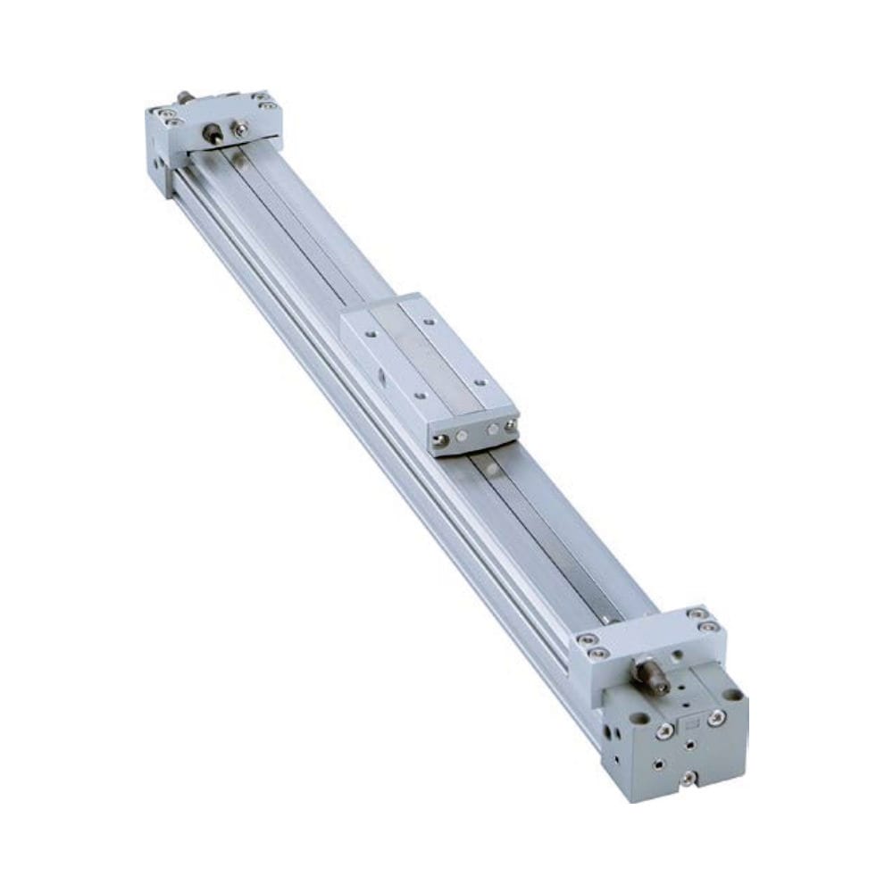
One more distinction matters on rodless cylinders. Running accuracy describes how the carriage follows an ideal path. End-position repeatability describes where it stops. A carriage can travel straight but stop inconsistently, or repeat against a rigid stop while its path deviates under moment load.
How Should Cylinder Repeatability Be Measured?
NIST warns that a repeatability standard deviation from one group of repetitions is not a reliable precision estimate. Its published example uses 6 measurements per sequence across multiple days and pools 30 degrees of freedom. The lesson is not a universal cycle count; it is to separate short-term repeatability from day-to-day variation (NIST repeatability analysis, accessed 2026).
Start by defining the measurand. Measure the carriage, fixture, tool center point, or part datum that the process actually uses. A piston position can be a useful diagnostic signal, but it may not represent the final process coordinate.
For repeated measured positions , calculate the mean position:
The signed mean position error relative to the calibrated reference is:
Estimate short-term scatter with the sample standard deviation:
Here, is the number of observations, is the mean measured position, is signed error, and describes dispersion under the stated test conditions. Do not label as 99.7% confidence unless the distribution, sampling plan, coverage statement, and uncertainty method justify that interpretation.
A defensible test sequence
- Establish the reference. Use a calibrated datum and record the measurement-system resolution and uncertainty.
- Stabilize the machine. Bring pressure, temperature, lubrication state, load, and seals to the intended test condition.
- Fix the motion profile. Record supply pressure during motion, valve command, flow-control setting, speed, approach direction, cushion setting, and settling time.
- Measure the process datum. Capture every result without moving the gauge or redefining zero.
- Repeat the test block. Run short-term blocks, then repeat across shifts, warm-up states, or days when long-term capability matters.
- Test both directions when relevant. Hysteresis and backlash disappear from a one-direction test.
- Preserve the raw data. A mean and standard deviation alone can hide drift, two clusters, rebound, or occasional sticking.
What if the first ten stops look perfect? Keep the test running through the actual thermal and production states. Short-term grouping and production capability answer different questions.
How Do End-Stop and Mid-Stroke Positioning Differ?
Festo lists ±0.05 mm repetition accuracy for the DLGF-KF guided rodless drive, while Enfield lists typical S2 servo-pneumatic positional accuracy of ±0.1% to 1% of full scale. The first is a model-level repetition figure; the second belongs to a feedback-controlled positioning architecture and scales with the measuring range (Festo DLGF, 2025; Enfield S2, accessed 2026).
End-stop motion
In a two-position application, a cylinder often supplies force and motion until a mechanical reference stops the tooling. The stop face, mounting stiffness, guide, impact energy, approach speed, and rebound then dominate the final coordinate. Adjusting the stop can reduce a constant offset, but it does not repair wide scatter or thermal drift.
This is why a repeatable pneumatic end position can be a property of the fixture rather than the cylinder alone. The cylinder must reach the stop with enough net force, but the physical datum may be outside the actuator. Specify the complete load path.
Mid-stroke motion
Stopping between end caps is a control problem. A basic directional valve and two magnetic switches can create coarse sequence points, but the piston continues moving during valve response, pressure equalization, and deceleration. Load changes and seal friction alter that stopping distance.
Closed-loop mid-stroke positioning normally needs continuous feedback, a proportional or servo valve, a controller, and a suitable mechanical guide. The servo-pneumatic positioning guide covers that architecture. Air compressibility remains part of its tuning limit, as explained in the air-compressibility control guide.
Building a Complete Position Error Budget
Parker states a GDL carriage running accuracy of ±0.03 mm per meter when the mounting rail stays within about 0.06 mm straightness deviation per meter. This conditional figure shows how installation quality enters the result before valve timing, sensor error, load deflection, or stop compliance are considered (Parker rodless-cylinder catalog, accessed 2026).
An initial worst-case screening budget can be written as:
Each term is a nonnegative allowance for one error source, and is the measurement contribution used by the chosen uncertainty method. This arithmetic sum is conservative. Do not replace it with a root-sum-square calculation unless the components, distributions, correlations, and coverage assumptions are defensible.
Useful evidence comes from synchronized data. Record valve command, both cylinder-port pressures, position feedback, and the external tooling measurement on one time base. The trace can separate an electrical command delay from pneumatic motion, mechanical rebound, guide movement, or measurement noise.
How Do You Set a Defensible Acceptance Limit?
ISO 15552 covers interchangeable cylinder dimensions for 32 mm to 320 mm bores and a maximum rated pressure of 1,000 kPa, or 10 bar. It does not establish a universal positioning-repeatability value. Dimensional interchangeability therefore cannot serve as evidence that two cylinders will stop within the same tolerance (ISO 15552, confirmed 2025).
Write the acceptance condition before selecting hardware. At minimum, record:
| Specification item | Example of a testable entry |
|---|---|
| Measured datum | Center of fixture pin relative to machine datum A |
| Target and tolerance | with upper and lower limits |
| Stop type | External hardened stop, cylinder end cap, or controlled mid-stroke stop |
| Approach | Extend only, retract only, or both directions |
| Load case | Payload, orientation, moments, and process force |
| Pneumatic state | Dynamic inlet pressure range, exhaust arrangement, speed, and air preparation |
| Timing | Command point, contact point, and measurement settling delay |
| Test blocks | Short-term block plus warm, cold, shift, or post-maintenance blocks |
| Reported results | Mean, signed error, standard deviation, range, maximum absolute error, and failures |
For an individual observation, the simplest pass condition is:
Here, is the largest observed absolute error and is the process limit. This rule evaluates the tested sample only. It is not a promise about every future cycle, so production risk may require a larger validation plan, monitoring, or a capability analysis agreed with the quality team.
Do not let an in-position bit become the acceptance measurement by default. The bit may be generated from a sensor window that is wider than the process tolerance. Verify the actual datum independently before relying on the PLC status.
Which Actuator Architecture Fits the Positioning Requirement?
Festo states that selected pneumatic mini slides can achieve 0.01 mm repetition accuracy, while Enfield’s feedback-controlled S2 system lists typical positional accuracy of ±0.1% to 1% of full scale. These values show that architecture, travel range, guidance, feedback, and test conditions matter more than the broad label “pneumatic cylinder” (Festo linear slides, accessed 2026; Enfield S2, accessed 2026).
| Architecture | Best fit | Position reference | Main verification risk |
|---|---|---|---|
| Standard cylinder with external stop | Two-position clamp, pusher, gate, or transfer | Mechanical stop or fixture datum | Stop compliance, rebound, guidance, and load variation |
| Guided cylinder or pneumatic slide | Compact repeated motion with moment loads | Integrated stop and guide | Product-specific loading and mounting conditions |
| Rodless cylinder with external guide and stop | Long-stroke transfer with defined endpoints | External stop or controlled carriage datum | Rail alignment, carriage moments, coupling, and impact |
| Servo-pneumatic axis | Variable intermediate positions or controlled deceleration | Continuous feedback and controller target | Tuning, air compressibility, friction, pressure, and sensor range |
| Electric servo axis | Many programmed positions and complex profiles | Encoder and calibrated mechanical transmission | Backlash, compliance, thermal growth, and drive tuning |
A standard cylinder is often sufficient when a rigid external stop defines the process position. Servo pneumatics becomes relevant when the commanded point changes or the motion profile must be controlled. An electric axis is usually easier to justify when the job requires many positions, synchronized motion, or traceable trajectory data.
The choice should follow the tolerance audit, not precede it. The cylinder and electric actuator precision comparison covers the wider technology decision. For long-stroke mechanics, review the rodless cylinder range with the actual load and moment directions.
A Practical Commissioning and Troubleshooting Sequence
SICK lists a minimum 2 kHz sampling rate for the MPS-G, alongside typical 0.3 mm linearity error and 0.05 mm same-direction repeatability at 25 °C. A fast data stream can therefore report position frequently without proving equal whole-axis accuracy. Commissioning must compare the signal with the external process datum (SICK MPS-G, 2025).
Use this sequence when the position result misses its limit:
- Confirm the datum and gauge. Check calibration, mounting, zero, resolution, contact direction, and measurement uncertainty.
- Separate command from motion. Compare PLC command, valve output, pressure response, piston feedback, and external datum.
- Check approach direction. If the error changes sign, investigate backlash, hysteresis, friction, and sensor teach direction.
- Inspect the stop and guide. Look for loose fasteners, impact marks, stop deformation, carriage clearance, rail misalignment, and bracket flex.
- Repeat with the production load. An unloaded setup test cannot represent payload moment, fixture compliance, or process force.
- Check dynamic pressure. Static regulator pressure can look normal while the point-of-use pressure collapses during motion.
- Test thermal states. Compare cold start, stabilized production, and restart after a long dwell.
- Review the acceptance logic. Confirm settling time, measurement window, rejected outliers, and fault behavior.
In our experience, the most revealing plot carries command, pressure, sensor position, and external tooling position on the same time axis. If the sensor trace repeats but the external datum moves, the fault branch is mechanical or metrological. If both move together, investigate the pneumatic and control chain first.
Record the final configuration after the machine passes: cylinder and sensor part numbers, stop setting, guide alignment, regulator setting, valve and flow-control codes, payload, software revision, test temperature, raw measurements, and calculated results. That record makes a post-maintenance comparison possible.
Pneumatic Cylinder Positioning FAQs
Festo publishes product-specific pneumatic repetition figures from 0.01 mm for selected mini slides to ±0.05 mm for the DLGF-KF guided rodless drive. Enfield instead expresses S2 servo-pneumatic accuracy as ±0.1% to 1% of full scale. The correct answer therefore begins with the exact architecture and acceptance test, not one universal cylinder value.
Is repeatability the same as accuracy for a pneumatic cylinder?
No. Repeatability describes the scatter among repeated measured positions under stated conditions. Accuracy describes agreement with a reference, but a numerical specification should identify signed error, maximum absolute error, or uncertainty. A cylinder can repeat tightly with a constant offset, or average near the target while individual stops scatter too widely.
How many cycles should a pneumatic cylinder repeatability test use?
There is no universal cycle count for every application. Choose the sample plan from the tolerance, failure risk, expected drift, and required confidence. Use short-term blocks to estimate repeatability, then repeat across warm-up, days, loads, or maintenance states when those changes occur in production. Preserve raw data rather than reporting only an average.
Does a 0.01 mm position-sensor resolution mean 0.01 mm cylinder accuracy?
No. SICK lists typical 0.01 mm resolution, 0.3 mm linearity error, and 0.05 mm same-direction repeatability for one MPS-G configuration at 25 °C. The complete machine also contains guide, coupling, stop, load, control, structure, and measurement errors. Sensor resolution is only one line in the error budget.
Can a magnetic cylinder switch provide precise stopping?
A discrete switch reports entry into a magnetic operating window; it does not physically stop the piston. Final position also depends on valve delay, piston speed, pressure, exhaust, friction, cushioning, rebound, PLC timing, and the mechanical datum. Use a rigid stop for suitable endpoint work or continuous feedback for controlled intermediate positioning.
Are rodless cylinders inherently more repeatable than rod-type cylinders?
Not universally. A rodless layout avoids an extending piston rod and can simplify long-stroke packaging, but positioning still depends on its guide, carriage, coupling, mounting, stop, load moments, and control method. Compare the exact models under the same test conditions. Do not convert a running-straightness value into an endpoint-repeatability claim.
Sources and technical references
- NIST, TN 1297 Appendix D1 Terminology, accuracy, repeatability, reproducibility, and measurement terminology; retrieved 2026-07-23.
- NIST/SEMATECH, Variability, short-term repeatability and long-term variability; retrieved 2026-07-23.
- NIST/SEMATECH, Analysis of Repeatability, repeated blocks and pooled repeatability estimates; retrieved 2026-07-23.
- ISO 15552:2018, interchangeable dimensions for specified pneumatic cylinder families, confirmed 2025; retrieved 2026-07-23.
- Festo, DLGF-KF Linear Drives, model-specific repetition accuracy, pressure, speed, guide, and cushioning data; retrieved 2026-07-23.
- Festo, Pneumatic Linear Slides, product-family repetition guidance; retrieved 2026-07-23.
- Parker, Rodless Pneumatic Cylinder Catalog 0961-1, GDL running accuracy and mounting conditions; retrieved 2026-07-23.
- SICK, MPS-G with Analog Output Operating Instructions, resolution, linearity, repeatability, sampling, and drive-dependence; retrieved 2026-07-23.
- Enfield Technologies, S2 Cylinder Positioning System Datasheet, full-scale positional accuracy and feedback-control architecture; retrieved 2026-07-23.