

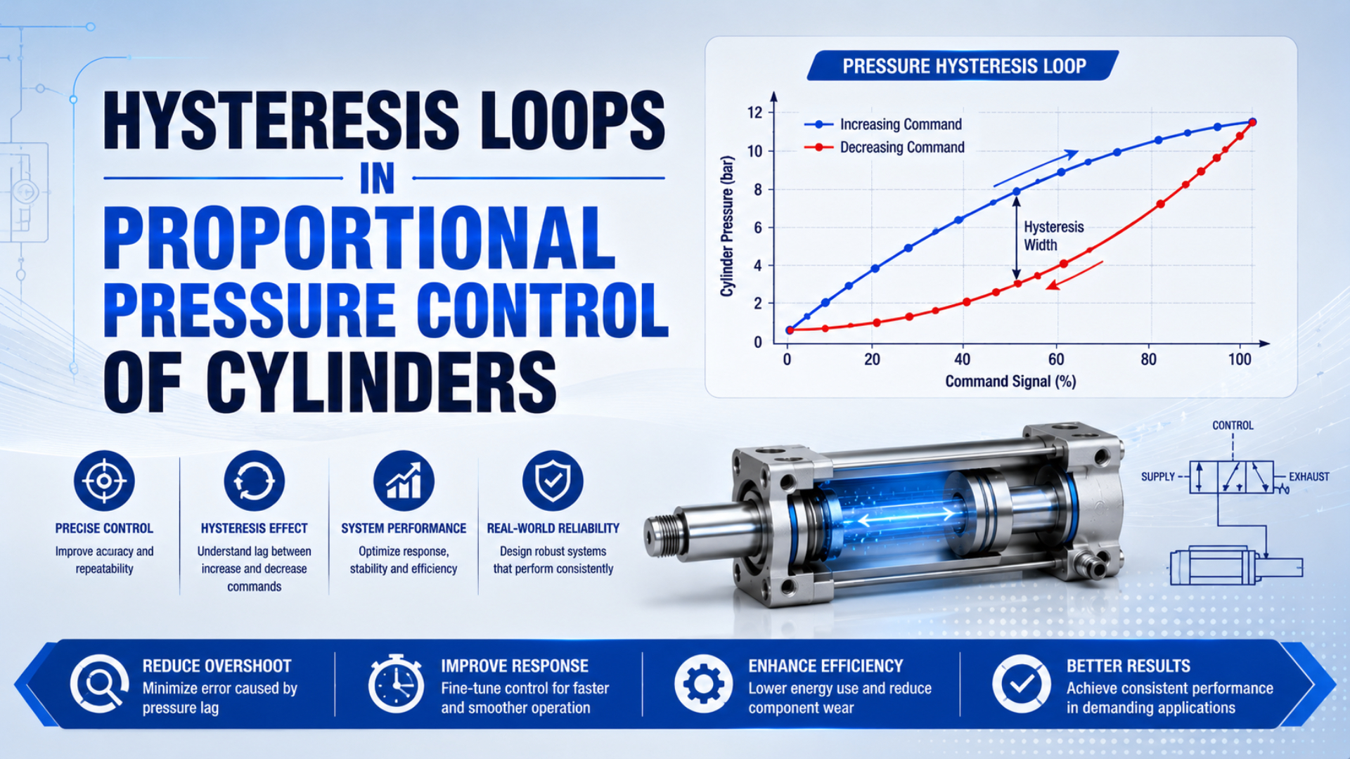
A hysteresis loop shows whether the same pressure command produces a different measured result after an upward approach than after a downward approach. The result is useful only when the input, output, sweep method, settling rule, full-scale basis, and pneumatic boundary are stated together.
That boundary is the practical issue in a cylinder system. A command-to-regulator-pressure plot tests a different chain from a command-to-cylinder-force or command-to-position plot. The latter can include regulator behavior, pressure-sensor error, tubing delay, chamber pressure, seal friction, guide load, linkage compliance, and the controller.
Key Takeaways
- Measure rising and falling output at identical input points; don’t estimate hysteresis from the visual width of an arbitrary loop.
- Use settled steps for a static test and a separate timed ramp or waveform for dynamic tracking.
- Record command, regulator outlet pressure, cylinder-chamber pressure, and force or position on one time base.
- Set acceptance limits from the exact component specification and the machine’s process tolerance, not a universal percentage.
What Does a Hysteresis Loop Actually Measure?
Bürkert defines valve hysteresis as the greatest fluidic-output difference between upward and downward traversals of the full electrical input range, normalized to maximum fluidic output (Bürkert proportional valve overview, accessed July 23, 2026). Hysteresis is directional path dependence at matched input values, not generic delay or random scatter.
Choose one input and one output before collecting data. For an electro-pneumatic regulator test, may be a 0-10 V command and the regulated outlet pressure. For a cylinder force test, can remain the electrical command while becomes load-cell force. Those plots answer different questions.
The selected output also determines the full-scale denominator. A 0.5% FS pressure specification cannot be compared directly with a force loop normalized to maximum load-cell force or a position loop normalized to cylinder stroke. The proportional-valve hysteresis and linearity guide covers component specifications; this article concentrates on the installed pressure-control chain.
Name every loop as an ordered pair: command-pressure, pressure-force, force-displacement, or command-position. The word “hysteresis” alone hides the measurement boundary and encourages unlike percentages to be added together.
Static Hysteresis Versus Dynamic Lag
ISO 6358-1:2013 defines steady-state pneumatic flow testing but explicitly excludes regulators with internal feedback and components such as cylinders that exchange energy with the fluid (ISO 6358-1, 2013). A cylinder pressure-loop test must therefore declare its own static or dynamic purpose instead of borrowing a universal ramp rate from that standard.
Static hysteresis is the direction-dependent separation that remains after matched rising and falling command levels satisfy a documented stabilization rule. Retain the settled value at each level. Fixed delays such as 30 seconds aren’t automatically correct; the required dwell depends on regulator response, downstream volume, leakage, sensor filtering, and process motion.
Dynamic lag is the time-dependent difference between the command and measured response during a declared ramp, triangle wave, sine wave, or production profile. Increasing the command rate can widen the plotted loop because filling, exhausting, sensor filtering, controller sampling, tubing restriction, and air compressibility introduce phase lag. The air-compressibility control guide explains that dynamic path.
Why separate the tests? A device may have a narrow settled loop but a wide high-speed loop, or it may settle slowly to two direction-dependent values. Combining both into one “hysteresis percentage” prevents a useful diagnosis.
| Test | Primary question | What must stay fixed | Reported result |
|---|---|---|---|
| Settled staircase | Does direction change the steady output at the same input? | Step levels, dwell criterion, supply, load, temperature | Maximum matched-point separation and repeatability |
| Timed ramp | Can the loop follow a declared command rate? | Ramp rate, sample rate, filters, volume, load | Directional separation versus command and time |
| Production profile | Does the machine meet its process requirement? | Recipe, tooling, payload, orientation, supply | Force, pressure, position, overshoot, settling, cycle result |
Loop area needs the same caution. Area in a voltage-pressure plot has units such as volt-bar and is not pneumatic energy. Treat it as a curve descriptor unless the axes are a work-conjugate pair and the normalization is defined.
A Repeatable Cylinder Hysteresis Test Procedure
ISO 4414:2010 addresses safety and predictable operation across pneumatic-system installation, adjustment, use, and maintenance, while a 2026 amendment to ISO 6358-1 specifically addresses measurement uncertainty (ISO 4414, 2010; ISO 6358-1 Amendment 2, 2026). A useful hysteresis test needs both controlled hazards and a traceable measurement plan.
Restrain the load and define the safe behavior for power loss, signal loss, and air loss before exercising the full range. A pressure command can move the cylinder unexpectedly after friction breaks away. Don’t rely on a PLC stop alone when stored pneumatic energy can still move the mechanism.
Record the following test configuration:
- complete regulator or valve model, firmware, command type, and pressure range;
- inlet pressure measured during the test, not only the upstream regulator setting;
- downstream tube length and inside diameter, fittings, silencers, and chamber volume;
- cylinder bore, rod diameter if applicable, stroke, orientation, guide, payload, and mechanical restraint;
- pressure-sensor range, location, calibration status, accuracy, hysteresis, filter, and sample rate;
- load-cell or position-sensor range, mounting, calibration status, and sample rate;
- air and ambient temperature, air-quality condition, and lubrication state where applicable;
- command levels, approach direction, dwell or ramp rule, repeats, and acceptance calculation.
Use common timestamps for all channels. A separate PLC trend and handheld gauge log cannot reliably show which event occurred first. Clock-aligned traces let you see whether the regulator pressure changed, the cylinder chamber followed, and the load finally moved.
For a static test, choose enough matched points to reveal the curve without claiming a universal step size. Approach the lower endpoint from the same precondition, run the entire rising sequence, hold or condition the upper endpoint as declared, then return through the identical command points. Repeat complete loops to separate hysteresis from same-direction repeatability.
Instrument capability belongs in the acceptance rule. If the expected separation is close to transducer uncertainty, noise, quantization, or supply drift, use a guard band or improve the measurement system. Reporting more decimal places doesn’t improve the evidence.
How Is Maximum Pressure Hysteresis Calculated?
SMC lists 0.5% FS or less hysteresis for its ITV electro-pneumatic regulator family and reports linearity, repeatability, and sensitivity separately (SMC ITV web catalog, accessed July 23, 2026). Use the same separation: calculate hysteresis from matched rising and falling pressures, then report other error terms independently.
Let be the electrical command, the settled pressure on the rising path, the settled pressure on the falling path, and the declared pressure span. The normalized maximum pressure hysteresis is:
is pressure hysteresis as a percentage of the declared span. The numerator and denominator must use the same pressure units. State whether pressure is gauge or absolute and define numerically. If the regulated range is not zero-based, use rather than silently dividing by the upper endpoint.
Also report the absolute maximum separation:
is often more useful in a machine error budget because it can be compared with the permitted pressure band. Record the command where it occurs. A single percentage without its pressure span cannot be converted back into a process consequence.
Don’t use horizontal curve width when command is on the horizontal axis and pressure is on the vertical axis. Horizontal separation answers a different inverse question: how much command difference is needed to obtain the same output from opposite directions. Both can be calculated, but they need different names and denominators.
Which Signals Separate Regulator Error from Cylinder Error?
A 2025 single-acting-cylinder study logged valve command, actuating pressure, displacement, motion state, and measured force; its loading and unloading curves shifted with displacement (Actuators research article, 2025). That measurement chain shows why one command-force loop cannot identify which component created the observed separation.
Collect at least four aligned signals when the process variable is force or position:
- Command : the value delivered to the regulator or valve, preferably with actual analogue current or voltage when available.
- Regulator outlet pressure : measured close to the regulator to evaluate its command-pressure behavior.
- Cylinder chamber pressure : measured near the working chamber to expose tubing, fittings, exhaust restriction, and downstream volume.
- Process output: load-cell force or position at the machine’s acceptance datum.
Interpret the pairs in order:
| Observed separation | Likely boundary | Checks before replacing hardware |
|---|---|---|
| Command to regulator pressure | Regulator, command electronics, internal sensor, or supply condition | Actual input signal, exact model specification, inlet pressure, exhaust, settings, temperature |
| Regulator pressure to chamber pressure | Pneumatic path or dynamic test method | Tube ID and length, fittings, silencer, check valves, leakage, chamber volume, ramp rate |
| Chamber pressure to force | Cylinder and mechanism | Seal friction, side load, guide alignment, opposing pressure, linkage ratio, compliance, load-cell mounting |
| Chamber pressure to position | Complete motion axis | Net force, payload, friction, cushions, stops, encoder mounting, controller, approach direction |
Pressure alone doesn’t establish cylinder force. For a double-acting cylinder, a useful force balance is:
and are chamber pressures, and are their effective piston areas, is the signed friction contribution, and represents the external resisting load in the chosen direction. The pressure-differential force guide explains the area terms.
The first relationship that develops directional separation is more diagnostic than the widest final loop. If command-to-pressure is tight but pressure-to-force opens, replacing the proportional regulator is unlikely to remove the mechanical path dependence.
How Can You Distinguish Friction, Delay, and Sensor Effects?
Experimental work on pneumatic cylinders found nonlinear pre-sliding behavior and a friction-force versus displacement loop whose size changed with chamber pressure (Bo et al., 2014). Friction is therefore a plausible cylinder-level source, but a loop shape alone does not prove that the seal is responsible.
Use controlled changes rather than visual guesses:
- Hold the command rate constant and change dwell. If the separation shrinks as the output is allowed to settle, dynamic lag or filtering is involved. A residual settled gap points toward static path dependence.
- Move the chamber sensor. A large difference between regulator-port and cylinder-port pressure under flow points to the pneumatic path, not automatically to regulator hysteresis.
- Repeat without cylinder motion when the circuit permits it safely. A regulator-pressure loop with a fixed downstream volume helps separate regulator behavior from moving seals and mechanics.
- Compare force at fixed position. If pressure-force separation changes with position, guide load, seal deformation, linkage geometry, or structural compliance may be part of the result.
- Reverse mechanical load while preserving the pressure sequence. A shifted force or position loop can expose gravity, side load, backlash, or asymmetric restraint.
- Use an independent pressure instrument. Agreement between two sensors reduces the chance that sensor hysteresis, range, filtering, or mounting is being mistaken for regulator error.
- Repeat at declared temperatures and supply pressures. Report the specific conditions instead of applying a generic seasonal correction.
Deadband requires a separate test. It asks how far the input must change before a declared output response occurs, often after a reversal. Hysteresis compares two outputs at the same input. See the proportional-valve deadband guide before assigning one percentage to both effects.
Irregular loops deserve a raw-trace review. Saturation, command clipping, pressure ripple, sensor quantization, loose wiring, mechanical impacts, and cycle-to-cycle drift can produce shapes that are neither a stable hysteresis characteristic nor a repeatable dynamic response.
What Is an Acceptable Hysteresis Limit?
SMC specifies 0.5% FS or less for an ITV family, while Festo lists 0.5% FS hysteresis and 1.25% FS total accuracy for one VPPM configuration (SMC ITV, accessed July 23, 2026; Festo VPPM, accessed July 23, 2026). These are model-specific component examples, not universal cylinder-system limits.
Build two acceptance layers:
- Component conformance: compare the regulator with its exact data-sheet definition, pressure range, supply condition, output variable, and test method. Don’t substitute another series’ percentage.
- Machine acceptance: define the permitted pressure, force, or position difference under the production load, direction, speed, temperature, and supply condition.
Convert the process tolerance into the measured output unit. If the operation permits a declared force band, test force at the process datum with the real tooling. If only pressure is measured, document the validated pressure-to-force relationship and its friction, opposing-pressure, geometry, and uncertainty allowances. The proportional pressure regulator guide explains why regulator pressure is not automatically process force.
An error budget should keep terms separate until their combination rule is justified:
| Contribution | Example acceptance evidence |
|---|---|
| Regulator hysteresis | Manufacturer limit or incoming test using the same defined output and span |
| Pressure sensor | Calibration, hysteresis, repeatability, range, temperature, and uncertainty data |
| Pneumatic path | Dynamic pressure difference between regulator and chamber under the declared profile |
| Cylinder and mechanics | Bidirectional force or position measurements at stated load and position |
| Controller | Tracking, overshoot, settling, saturation, and fault-response records |
Do not add all maximum percentages as though they peak together with the same sign and denominator. A conservative limit may use worst-case addition, root-sum-square treatment, measured combined performance, or another documented method. The engineering team must state which model matches the risk and evidence.
How Should Hysteresis Be Corrected?
In a 2025 single-acting-cylinder experiment, command smoothing reduced overshoot and steady error for that rig but increased settling time as smoothing increased (Actuators, 2025). The result illustrates a general commissioning lesson: a correction can improve one metric while worsening another, so compensation must follow fault removal and complete-loop retesting.
Use this order:
- Verify the measurement. Check calibration, ranges, timestamps, filters, units, command scaling, and the full-scale denominator.
- Remove physical faults. Correct contamination, blocked exhausts, unstable supply pressure, damaged seals, side loading, misalignment, loose couplings, and unsuitable sensor mounting.
- Stabilize the test boundary. Fix volume, tube geometry, load, position, temperature, sweep method, and preconditioning.
- Characterize both directions. Save repeated rising and falling curves, not just one maximum percentage.
- Apply documented device settings. Use only approved gain, response, dither, PWM, or filter settings for the selected hardware.
- Add direction-aware compensation if needed. A lookup table or feedforward correction must include approach direction when one curve cannot represent both paths.
- Protect the feedback loop. Apply output limits and anti-windup, then retune with the real pneumatic delay and mechanical load.
- Revalidate production conditions. Test force or position, not merely regulator pressure, when that is the acceptance variable.
Controller feedback can reduce tracking error, but it doesn’t erase the underlying component or mechanical characteristic. Higher gain may instead produce hunting when delay, friction, saturation, or deadband prevents a smooth correction. Use the proportional-valve PID tuning guide after the static and dynamic boundaries are measured.
A compensation table should represent a healthy, repeatable system. If the curve changes materially after cleaning, warm-up, load reversal, or maintenance, the table is absorbing an uncontrolled condition rather than correcting a stable characteristic.
Proportional Pressure Hysteresis FAQs
SMC and Festo both publish 0.5% FS hysteresis for specific electro-pneumatic regulator families, yet their documentation keeps hysteresis separate from other accuracy terms (SMC ITV; Festo VPPM, accessed July 23, 2026). These questions explain how to preserve that measurement boundary in a complete cylinder system.
Is a Wider Dynamic Loop Always Evidence of More Static Hysteresis?
No. A faster ramp can widen a command-pressure or command-force loop through fill and exhaust delay, tubing restriction, chamber volume, filtering, sampling, and mechanical motion. Repeat the test as a settled staircase. Report the remaining matched-point separation as static hysteresis and keep the rate-dependent loop as a separate dynamic result.
Should Hysteresis Be Measured at the Regulator or the Cylinder?
Measure both when the machine variable matters. A sensor near the regulator tests its local outlet-pressure relationship. A sensor near the cylinder includes the connecting pneumatic path. Comparing synchronized readings shows whether separation appears before or after the tubing, fittings, valves, and chamber volume. Always state the sensor location with the result.
Can Pressure Hysteresis Be Converted Directly into Cylinder Force Error?
Not without a validated force model. Net cylinder force depends on both chamber pressures, their effective areas, signed friction, external load, linkage geometry, and position. Use a load cell at the process datum when force is the acceptance variable. Pressure-derived force remains an estimate unless those additional terms and uncertainties are controlled.
Can a PID Controller Eliminate Hysteresis?
Feedback can reduce measured tracking error inside the loop’s available authority and bandwidth, but it doesn’t remove valve friction, sensor hysteresis, seal behavior, or backlash. Excess integral action can accumulate while the output is inactive and then overshoot. Characterize both directions, correct physical faults, apply anti-windup, and retest the production profile.
How Often Should a Hysteresis Baseline Be Rechecked?
Use a risk-based interval tied to process capability, maintenance, contamination exposure, temperature range, and observed drift. Establish a baseline after commissioning and repeat it after regulator, sensor, cylinder, seal, tubing, firmware, or controller changes. Trend the raw curves and test conditions; a universal quarterly interval or fixed percentage increase isn’t defensible.
Sources and Technical References
The article uses eight manufacturer, standards, and experimental sources. Product values remain tied to the named family and are not presented as universal pneumatic-cylinder acceptance limits.
- Bürkert, Proportional Valves Product Overview, definitions of hysteresis, sensitivity, linearity, and repeatability. Accessed July 23, 2026.
- SMC, ITV Electro-Pneumatic Regulator Web Catalog, model-family hysteresis, linearity, repeatability, and sensitivity. Accessed July 23, 2026.
- Festo, VPPM Proportional Pressure Regulator, model-specific hysteresis, linearity, reproducibility, and total accuracy. Accessed July 23, 2026.
- ISO 6358-1:2013, scope, steady-state method, and exclusions for regulators and cylinders. Accessed July 23, 2026.
- ISO 6358-1:2013/Amd 2:2026, evaluation of measurement uncertainty. Accessed July 23, 2026.
- ISO 4414:2010, general rules and safety requirements for pneumatic systems and components. Accessed July 23, 2026.
- Bo et al., Experimental Investigation of Friction Behavior in Pre-Sliding Regime for Pneumatic Cylinder, experimental pressure, displacement, and friction-loop evidence, 2014. Accessed July 23, 2026.
- Data-Driven Feedforward Force Control of a Single-Acting Pneumatic Cylinder with a Nonlinear Hysteresis Characteristic, synchronized command, pressure, displacement, and force measurements, 2025. Accessed July 23, 2026.