

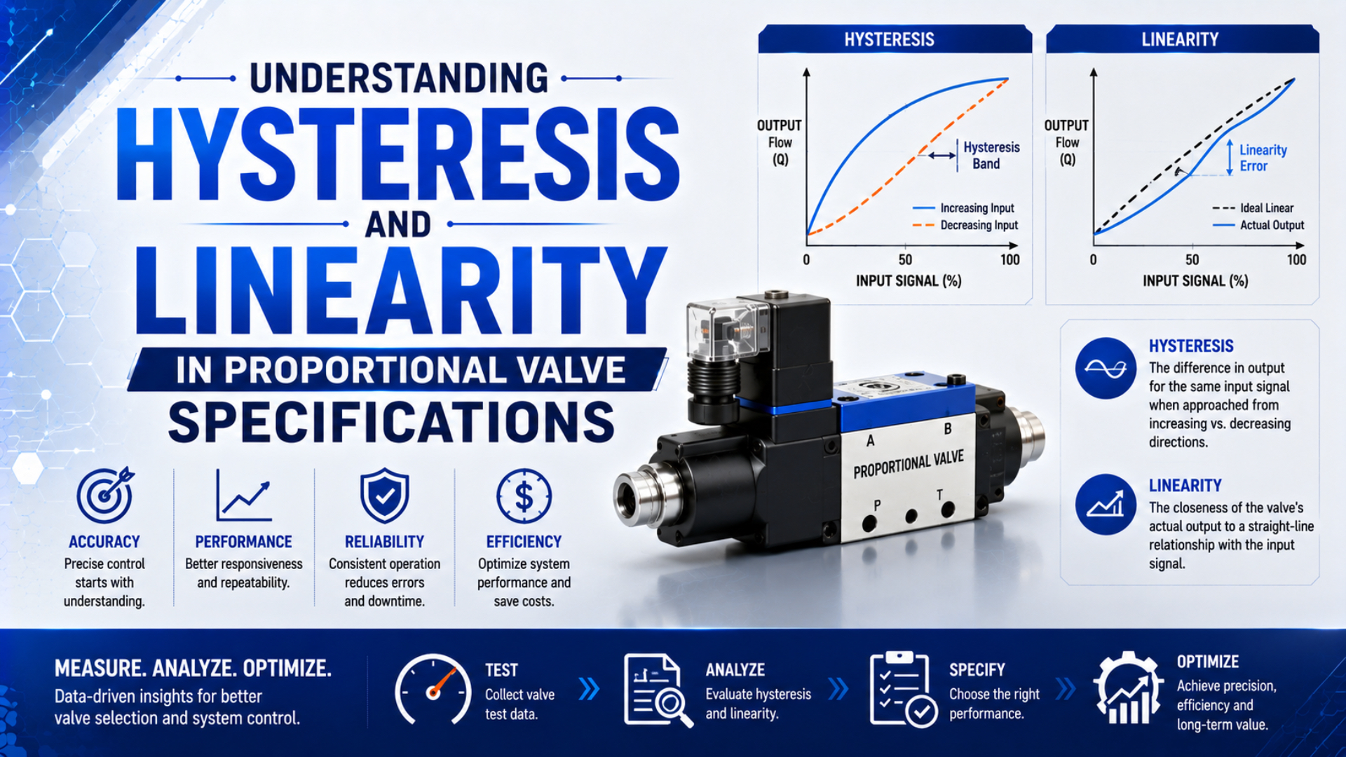
Hysteresis and linearity describe different errors in a proportional valve. Hysteresis compares the output at the same command while the command rises and falls. Linearity compares a measured characteristic with a stated reference line. Neither percentage is meaningful until the data sheet identifies the output variable, full-scale basis, test direction, and operating conditions.
That distinction matters when comparing valves. SMC, for example, specifies its ITV electro-pneumatic regulator with hysteresis of 0.5% full scale or less and linearity of ±1% full scale or less. Emerson lists hysteresis for one AVENTICS EV07 variant as 0.04 bar instead. The numbers use different forms, so a bare “0.5 versus 0.04” comparison would be wrong.
Key Takeaways
- Hysteresis compares rising and falling outputs at the same input; linearity compares output with a defined reference line.
- SMC specifies one ITV family at 0.5% FS hysteresis and ±1% FS linearity.
- Compare the same output variable, range, method, pressure, temperature, and flow state.
- Approve the complete pneumatic axis under its real load.
What Does Hysteresis Mean in a Proportional Valve?
Bürkert defines hysteresis as the greatest fluidic-output difference between upward and downward sweeps over the complete electrical input range, expressed against maximum fluidic output (Bürkert proportional valve overview, accessed 2026). It measures path dependence, not random variation or the smallest detectable command change.
For a test with command , rising output , falling output , and full-scale output , a normalized hysteresis value can be written as:
Here, is hysteresis in percent of full scale. The variable must be named, such as flow in standard liters per minute, regulated pressure in bar, or measured spool position in millimeters. Both sweeps must use the same range, supply, downstream condition, stabilization rule, temperature, and instrumentation. Otherwise the numerator includes changes that aren’t valve hysteresis.
What does the number mean in operation? If a controller approaches the same command from opposite directions, the valve may deliver different flow or pressure. Friction, magnetic behavior, sealing forces, and mechanical clearances can contribute, but a data sheet’s percentage is a measured characteristic under its stated test, not a diagnosis of one physical cause.
The most useful reading is therefore conditional: “maximum separation of these two measured curves under this method.” It isn’t a universal positioning error. A valve with low catalog hysteresis can still sit in an axis with seal stiction, load reversal, pressure variation, or sensor error. The closed-loop cylinder position guide treats those as separate contributors.
How Is Linearity Calculated?
Bürkert defines linearity as the maximum departure of a measured characteristic from an ideal straight characteristic, normalized to maximum fluidic output (Bürkert proportional valve overview, accessed 2026). A usable specification must also identify how that reference line is constructed, because endpoint and best-fit methods can yield different results.
A general normalized form is:
In this expression, is maximum linearity deviation in percent of full scale, is the measured output, and is the declared reference line at command . The full-scale output uses the same units as both outputs. The specification should say whether the result is signed, absolute, or written as a ± tolerance.
Why insist on the reference-line method? Imagine a smooth flow curve that bows above a line through its endpoints. A least-squares line can shift to share the deviation on both sides, while an endpoint line cannot. The same measurements can therefore produce two reported values. Ask for the curve and method before ranking suppliers.
The figure also explains why “nonlinear” doesn’t mean “uncontrollable.” A repeatable nonlinear curve can sometimes be characterized and compensated. An unstable or direction-dependent curve is harder to invert because one command doesn’t map to one output. Compensation still needs validation across pressure, temperature, wear, and production tolerances.
Hysteresis, Deadband, Sensitivity, Resolution, and Repeatability
SMC lists four separate performance terms for its ITV regulator: linearity of ±1% FS or less, hysteresis of 0.5% FS or less, repeatability of ±0.5% FS or less, and sensitivity of 0.2% FS or less (SMC ITV catalog, accessed 2026). They shouldn’t be used as synonyms.
| Term | Engineering question it answers | What the result needs |
|---|---|---|
| Hysteresis | Does output change when the same input is approached from opposite directions? | Rising and falling sweeps, maximum separation, normalization basis |
| Linearity | How far does a measured curve depart from the declared reference line? | Measured curve, reference-line method, maximum deviation |
| Deadband | How far can input move before output responds after a reversal or from a defined state? | Starting state, direction, response threshold |
| Sensitivity | What is the smallest input change that creates a measurable output change? | Step size, noise threshold, measurement resolution |
| Resolution | What is the smallest command or output increment the system can represent or distinguish? | Digital bit depth or measurement definition |
| Repeatability | How closely do repeated outputs agree when the same input is approached in the same way? | Repeated trials, approach direction, statistic, conditions |
Bürkert’s definitions are especially helpful here. It calls sensitivity the smallest setpoint difference that causes a measurable fluidic-output change, while repeatability is dispersion when the same input is approached repeatedly from the same direction. Hysteresis deliberately changes direction. Repeatability deliberately holds it constant.
Could deadband be caused by hysteresis? They can share mechanical causes, and both may appear around a command reversal, but the reported tests answer different questions. Keep the terms separate in a requirement. A supplier cannot prove a 0.2% sensitivity requirement merely by submitting a 0.2% repeatability result.
Why Can’t You Compare Percentages Without Test Conditions?
SMC states hysteresis as 0.5% FS or less for an ITV regulator, while Emerson states 0.04 bar for an AVENTICS EV07 variant (SMC ITV instruction manual, accessed 2026; Emerson EV07 product page, accessed 2026). One is normalized; the other is an absolute pressure difference.
Before comparing two rows, align these fields:
- Valve function: proportional pressure regulator, proportional flow valve, or proportional directional valve.
- Measured output: regulated pressure, normalized flow, mass flow, spool position, or another quantity.
- Normalization: full command span, rated output, maximum fluidic output, or a declared measuring span.
- Reference method: endpoint, best fit, zero-based line, or another manufacturer-defined construction.
- Sweep procedure: direction, rate, increments, dwell time, cycles, and whether preconditioning is used.
- Pneumatic state: inlet and outlet pressure, pressure loss, gas, temperature, flow state, and exhaust restriction.
- Electrical state: signal type, supply voltage, controller settings, PWM frequency, and filters.
- Measurement: instrument accuracy, sampling, averaging, and uncertainty treatment.
Flow notation can hide another mismatch. Bürkert’s overview gives a nominal gas-flow example in standard liters per minute at 20°C, 6 barg inlet, and 1 bar pressure loss, while defining standard conditions as 1,013.25 mbar absolute and 0°C. A competing catalog may use a different reference temperature or pressure drop. Match the bases before converting the curve.
This is why a normalized percentage isn’t automatically more transferable than an absolute value. It is easier to scale, but only within its declared range and definition. An absolute 0.04 bar result may be more immediately useful for a pressure tolerance, while a percent-of-flow result may suit a flow error budget. First match the metric to the controlled variable.
ISO 6358-1 provides steady-state flow-testing methods for pneumatic components with fixed or variable flow paths, but its scope excludes components with remarkable hysteretic behavior or internal feedback, including pressure regulators (ISO 6358-1:2013). Don’t cite it as a universal hysteresis procedure for every proportional pneumatic device.
How Do These Valve Errors Affect a Pneumatic Axis?
Festo describes a pneumatic positioning arrangement as a proportional directional valve combined with an external position controller and displacement encoder, rather than as a valve acting alone (Festo MPYE data sheet, accessed 2026). Valve hysteresis is therefore one contributor to axis behavior, not a direct statement of carriage-position accuracy.
In open-loop flow control, hysteresis can make a given command produce different cylinder speeds after acceleration and deceleration. Nonlinearity can make equal command increments produce unequal flow increments. The effect then passes through pressure-dependent valve flow, tubing resistance, chamber volume, seal friction, load force, and exhaust restriction. The proportional flow valve guide explains that pneumatic path.
In a closed loop, feedback can correct some predictable error, but correction isn’t free. The controller needs sufficient authority and bandwidth without exciting pneumatic compliance or friction. Near a reversal, valve hysteresis and cylinder stiction can combine into a wider apparent no-response region. Increasing gain may then create hunting rather than accuracy.
What should the machine specification say? Define the axis result separately from the valve component limits:
| Component acceptance | Complete-axis acceptance |
|---|---|
| Valve input-output hysteresis under a named bench test | Position or pressure error under actual load and motion |
| Valve linearity against a stated reference line | Trajectory error, overshoot, settling, and steady-state band |
| Same-direction valve repeatability | Bidirectional axis repeatability at declared positions |
| Flow or pressure range at stated pneumatic conditions | Cycle time with real tubing, fittings, silencers, and supply |
For a pressure-control application, also distinguish the valve’s own pressure characteristic from system compliance and downstream consumption. The proportional pressure regulator guide covers that boundary. For motion applications, proportional valve selection for precision control provides the broader architecture.
A Data-Sheet Comparison Workflow
An SMC ITV example separates 0.5% FS hysteresis, ±1% FS linearity, ±0.5% FS repeatability, and 0.2% FS sensitivity into distinct rows (SMC ITV catalog, accessed 2026). A sound comparison preserves those labels, then normalizes only measurements that truly share the same variable and method.
Use this sequence for each candidate:
- Classify the function. Is the device controlling pressure, flow, or both cylinder ports? Don’t compare a regulator’s pressure hysteresis with a directional valve’s flow characteristic.
- Copy the exact definition. Record the manufacturer’s wording, symbol, inequality, sign convention, and units.
- Name the denominator. Write the actual full-scale or span value beside every percentage. If it isn’t stated, mark the row incomplete.
- Identify the characteristic. Obtain the measured curve when possible. Note rising, falling, averaged, or single-direction data.
- Record conditions. Include supply, outlet, pressure drop, gas, temperature, flow state, signal, and electronics settings.
- Separate guaranteed and typical values. A typical curve doesn’t establish a production acceptance limit unless the supplier says it does.
- Convert to the application unit. Translate the valve limit into bar, liters per minute, or another controlled-output unit only after confirming its basis.
- Build an error budget. Keep valve, sensor, controller, air supply, mechanics, and load terms visible rather than adding unlike percentages blindly.
Suppose a regulator is rated over a 0 to 10 bar output range and its hysteresis is genuinely specified as 0.5% of that full-scale range. The corresponding catalog-limit contribution would be 0.05 bar under the stated test. That conversion does not predict machine pressure error; it merely expresses one component specification in the application’s unit.
The valve flow-chart interpretation guide is useful when the controlled output is flow rather than pressure. It also prevents a common category error: using a static coefficient or one flow point as though it described the entire proportional input-output characteristic.
How Should You Test Hysteresis and Linearity on the Machine?
ISO 6358-1:2013 defines steady-state flow-rate testing for pneumatic components, and ISO published Amendment 2 in 2026 to address measurement uncertainty (ISO 6358-1; ISO 6358-1:2013/Amd 2:2026). Those documents underline two essentials: stabilize the test state and report a result with a defensible measurement basis.
A practical component or incoming-inspection test should follow a written sequence:
- Install the exact valve, electronics, fittings, tubing, silencers, and measurement instruments named in the plan.
- Condition the air and stabilize supply pressure, downstream pressure, temperature, and electrical supply.
- Apply the manufacturer’s warm-up or preconditioning sequence. Record it rather than assuming “room temperature” is enough.
- Sweep the command upward in declared steps and dwell until the output meets the stabilization rule.
- Sweep downward using the same steps, dwell, and acquisition method.
- Repeat enough cycles to separate repeatability from a single hysteresis loop. Declare how the reported maximum is selected.
- Construct the agreed reference line and calculate linearity from the specified rising, falling, mean, or other declared curve.
- Save raw command, output, time, pressure, temperature, and configuration data with the calculated result.
Should the machine test copy a laboratory flow standard? Not necessarily. A production acceptance test may measure regulated pressure or axis motion rather than intrinsic valve flow. Its purpose and limits must be explicit. Use the catalog method for supplier conformance, then a separate application test for system performance. Don’t relabel one as the other.
Instrument capability belongs in the record. If the acceptance band is close to gauge accuracy, signal noise, resolution, or supply drift, the pass/fail decision may reflect the bench rather than the valve. State calibration status, range, sample rate, filtering, stabilization threshold, and uncertainty rule before collecting the first curve.
Practical Corrections for Hysteresis and Nonlinearity
Bürkert’s Type 8605 controller documentation explains that PWM frequency affects coil current ripple and valve response, with optimum settings dependent on valve type (Bürkert Type 8605 manual, accessed 2026). This makes dither or PWM tuning a product-specific commissioning task, not a universal cure for every hysteresis curve.
Choose the correction that matches the evidence:
- Reduce mechanical and pneumatic friction: correct contamination, damaged seals, misalignment, side load, and unsuitable lubrication according to the valve and actuator manuals.
- Stabilize operating conditions: regulate dynamic supply pressure, reduce unexpected exhaust restriction, and keep gas quality and temperature within the selected product limits.
- Use approved electronics settings: apply the manufacturer’s controller, PWM frequency, dither, and current limits. External dither can add output ripple, noise, heat, or wear if the valve isn’t designed for it.
- Calibrate a repeatable nonlinear curve: use a manufacturer-provided characteristic or a validated lookup table when the curve is stable enough to invert.
- Keep direction in the model when needed: one compensation curve may not represent both rising and falling paths. Direction-aware mapping adds complexity and still needs transition logic near reversal.
- Close the loop around the real variable: measure pressure, flow, or position when the process requires that output, then tune within the axis’s stability and safety limits.
- Select a better-matched valve: compensation cannot create flow capacity, remove unstable friction, or guarantee performance outside the documented range.
There is a useful order here: repair, stabilize, characterize, then compensate. If characterization comes first, the lookup table may absorb a blocked silencer, drifting regulator, or misaligned actuator. It will appear to work on that day and fail after maintenance. Compensation should describe the healthy system, not conceal a correctable defect.
If the main concern is flow capacity rather than characteristic error, use the pneumatic flow-control valve sizing guide as a separate check. An undersized valve can remain perfectly linear while the axis still misses speed and cycle-time targets.
What Should an RFQ or Acceptance Test Specify?
Emerson’s EV07 page reports hysteresis as 0.04 bar, whereas SMC’s ITV documentation reports 0.5% FS or less (Emerson EV07 product page, accessed 2026; SMC ITV manual, accessed 2026). An RFQ must therefore request definitions and conditions, not just “low hysteresis.”
Include the following in the commercial and technical package:
- Valve function, porting, medium, nominal size, rated range, and required output variable.
- Input type, input span, supply voltage, electronics, controller, and permissible settings.
- Required hysteresis, linearity, repeatability, sensitivity, and deadband as separate items where relevant.
- Units and normalization basis for every limit, including the numerical full-scale value.
- Reference-line method and whether the rising, falling, mean, or other curve is assessed.
- Supply pressure, downstream pressure or pressure loss, temperature, gas reference conditions, and stabilization rule.
- Sweep range, step size, rate, dwell, direction, preconditioning, and cycle count.
- Instrument range, accuracy, calibration, sampling, filtering, and uncertainty or guard-band rule.
- Whether the value is a guaranteed limit, typical value, initial inspection target, or ongoing machine requirement.
- Required raw curves, calculation file, valve identification, firmware, and test report.
For the complete machine, add payload, orientation, motion profile, tube and fitting arrangement, dynamic supply pressure, feedback sensor, controller task rate, and safe-state behavior. State axis acceptance separately: tracking error, repeatability, overshoot, settling, cycle time, and response to power or air loss.
A procurement table with blanks is better than assumed equivalence. Ask each bidder to fill the units, denominator, reference method, and conditions. Any blank stays an open technical deviation. That makes the final comparison auditable and prevents the lowest-looking percentage from winning on an undefined basis.
Proportional Valve Specification FAQs: What Should Engineers Check?
SMC’s ITV documentation places hysteresis at 0.5% FS or less beside ±1% FS linearity and ±0.5% FS repeatability (SMC ITV manual, accessed 2026). These five answers show how to keep the metrics separate and turn a catalog row into a testable valve or machine requirement.
Is Lower Hysteresis Always Better?
Lower hysteresis is generally helpful when the same command must give similar output after direction changes, but it isn’t the only selection criterion. SMC’s ITV example specifies 0.5% FS hysteresis separately from ±1% FS linearity. Confirm flow capacity, range, response, repeatability, conditions, safety, and total axis performance as well.
Are Linearity and Accuracy the Same Specification?
No. Linearity is maximum deviation from a declared reference line, while accuracy compares a result with a defined true or target value and includes additional error sources. A valve listed at ±1% FS linearity does not by itself guarantee ±1% pressure, flow, speed, or position accuracy in the assembled machine.
Can Hysteresis Be Added Directly to Linearity?
Not without a declared error model. Hysteresis is direction-dependent curve separation; linearity is departure from a reference line. Their maxima may occur at different commands and use different signs. Keep both terms visible, convert them to the same output unit when justified, and verify the worst required operating path with measured data.
Does Dither Remove Proportional-Valve Hysteresis?
It may reduce friction-related effects for a compatible valve and driver, but it isn’t universal. Bürkert’s Type 8605 manual makes PWM behavior dependent on valve type and frequency. Use only approved settings, then remeasure hysteresis, output ripple, temperature, noise, and stability. An arbitrary dither signal can trade one problem for another.
What Data Should I Request When a Catalog Lists Only a Percentage?
Ask for the measured output, numerical full-scale basis, rising and falling curves, reference-line method, pressures, gas, temperature, sweep rate, dwell, electronics, repeat count, and whether the limit is guaranteed or typical. SMC’s 0.5% FS notation is useful only when its range and test context travel with the percentage.
Sources and Technical References
The article uses 8 primary manufacturer or standards documents from SMC, Bürkert, Emerson, ISO, and Festo. SMC’s 0.5% FS hysteresis and ±1% FS linearity serve as a worked comparison, not as universal acceptance limits for other valve functions, output ranges, or test methods.
- Bürkert, Proportional Valves Product Overview, definitions for hysteresis, linearity, sensitivity, repeatability, and nominal gas-flow conditions.
- SMC, ITV Series Safety Instructions and Specifications, model-specific linearity, hysteresis, and repeatability limits.
- SMC, Electro-Pneumatic Regulator ITV Catalog, model-specific sensitivity and temperature characteristic alongside other specifications.
- Emerson, AVENTICS EV07 product record, an example of hysteresis stated in absolute pressure units.
- Bürkert, Type 8605 Operating Instructions, valve-dependent PWM frequency and controller behavior.
- ISO 6358-1:2013, scope and steady-state flow-testing framework for pneumatic components.
- ISO 6358-1:2013/Amd 2:2026, amendment addressing measurement uncertainty.
- Festo, MPYE Proportional Directional Control Valve Data Sheet, system boundary for pneumatic positioning with external controller and displacement feedback.