

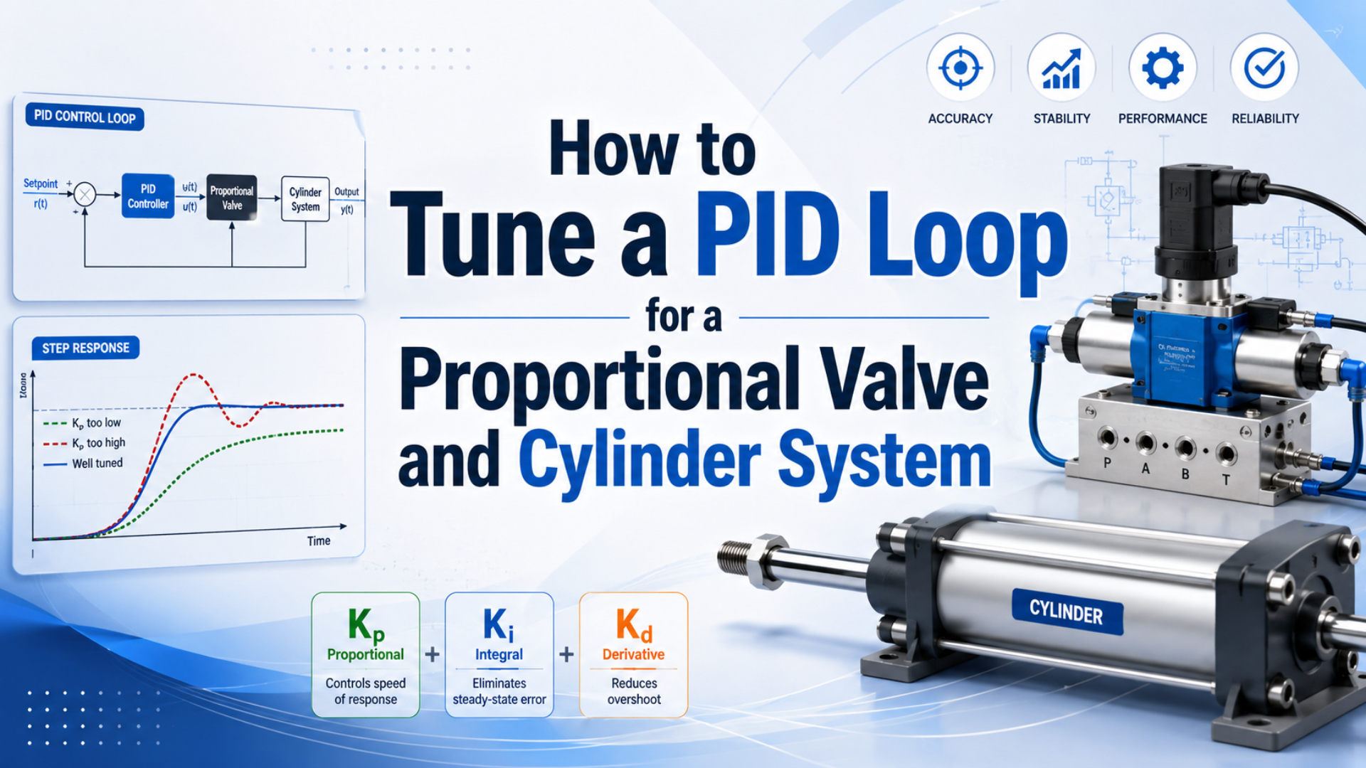
PID tuning for a proportional valve and cylinder is the controlled process of adjusting feedback gains after the valve, actuator, sensor, air path, mechanics, and controller limits have been verified as one system. Adjust those gains from recorded response traces, not from a universal table. Pneumatic position control changes with load, stroke position, friction, pressure, valve deadband, and trapped air volume.
The practical sequence is straightforward: define a safe test, verify signal polarity and valve neutral, begin with integral and derivative action disabled when the controller allows it, establish useful proportional response, add damping, and introduce integral action only for repeatable residual error. Test every accepted setting across the real operating envelope.
Key Takeaways
- PID gains are not portable until controller form, units, sample time, and filters match.
- Log setpoint, position, valve command, supply pressure, and both chamber pressures during every test.
- Fix saturation, deadband, friction, pressure loss, and sensor errors before asking PID gains to compensate.
The best tuning change is often no gain change at all. A trace that shows valve-command saturation, collapsing inlet pressure, or stepwise breakaway motion identifies a physical limit that more gain cannot remove.
What Must Be True Before You Tune the Loop?
Festo describes a servo-pneumatic positioning system as three core elements: a cylinder with displacement encoder, a proportional directional valve, and a position controller. PID tuning begins only after those three elements, the mechanical load, and the compressed-air path operate correctly and fail safely (Festo, accessed 2026).
Start by defining the controlled variable. This article assumes a closed-loop position axis where the controller commands a proportional directional valve and receives continuous position feedback. A proportional pressure regulator controlling force, or a proportional flow valve controlling open-loop speed, is a different plant and needs a different test design.
Before enabling automatic control, verify:
- The cylinder and load move freely through the intended test range.
- Guidance, couplings, tooling, stops, and sensor mounting are tight and aligned.
- Supply pressure remains stable during motion and both exhaust paths are unrestricted.
- Valve flow capacity is adequate in both directions at actual pressure ratios.
- Position feedback has the correct polarity, range, engineering units, and datum.
- Valve-command polarity, neutral region, positive limit, and negative limit are known.
- Loss of power, command, feedback, or air produces the machine’s defined safe state.
- Test speed, acceleration, travel, and force are reduced to safe commissioning limits.
Do not deliberately drive a production axis into sustained oscillation near hard stops, people, tooling, or an unsupported vertical load. If the selected controller offers manufacturer identification or autotuning, follow its commissioning manual because internal control structures and safety limits may differ from a generic PID block.
For valve and feedback selection, use the separate proportional-valve motion-control guide. If the valve command reaches its limit before the cylinder reaches the requested speed, estimate the actuator’s demand with the Cylinder Flow Requirement Calculator before continuing to tune.
Which PID Equation and Units Does Your Controller Use?
MathWorks documents two common continuous PID forms, parallel and standard, and separate discrete-time implementations with selectable integration and derivative-filter formulas. That difference is why Kp = 1 or Ki = 0.2 has no portable meaning until the controller form, units, sample time, and algorithms are recorded (MathWorks, accessed 2026).
In a parallel-form PID controller with a filtered derivative term, the controller transfer function can be written as:
is proportional gain, is integral gain, is derivative gain, and is the derivative-filter time constant. The error is , where is the commanded position and is measured position. The controller output becomes the valve command after scaling and limiting.
Some controllers instead use proportional gain with integral and derivative times, such as , , and . Others expose velocity gain, acceleration feedforward, dead-zone compensation, or vendor-specific damping parameters rather than a textbook PID. Convert gains only with the manufacturer’s documented relationship.
Record this controller identity before tuning:
| Setting | What must be documented | Why it changes the result |
|---|---|---|
| Controller type | P, PI, PD, PID, PIDF, or vendor-specific form | determines which actions are active |
| Mathematical form | parallel, standard, positional, or incremental | changes gain meaning and units |
| Sample time | controller execution interval | changes discrete integration and differentiation |
| Position units | mm, counts, percent of stroke, or engineering units | scales proportional and integral error |
| Output units | volts, current, percent, or signed command word | scales command authority and saturation |
| Integrator method | forward Euler, backward Euler, trapezoidal, or vendor method | changes discrete integral behavior |
| Derivative method | error or measurement, filtered or unfiltered | changes noise sensitivity and setpoint response |
| Output limits | permitted positive and negative command | defines saturation and anti-windup behavior |
Never copy gains from another machine unless this entire identity and the physical plant match. Even cylinders with the same bore can differ through stroke position, tube volume, valve size, payload, friction, and sensor scaling.
Define Acceptance Metrics Before Adjusting Gains
MathWorks defines default step-response rise time between 10% and 90% of the commanded change and uses a 2% settling threshold unless the user specifies another value. These are analysis conventions, not machine tolerances; the process owner must define the actual position band, dwell time, overshoot, and fault limits (MathWorks, accessed 2026).
Choose a representative but safe move that stays away from the end stops. Record the same move in both directions and use the same payload, pressure, profile limits, sampling, and filters while comparing controller changes.
At minimum, log:
- commanded position and motion-profile state
- measured position and calculated velocity
- raw and filtered sensor values when available
- unsaturated controller output and final limited valve command
- valve feedback or spool position if the valve provides it
- machine inlet pressure and both cylinder-port pressures
- load, cylinder position, air temperature, and elapsed operating time
- controller mode, active gain set, and fault status
Use the trace to calculate project-defined metrics:
| Metric | Practical definition | What it helps reveal |
|---|---|---|
| Rise time | time between stated lower and upper fractions of the move | response speed |
| Peak overshoot | largest position beyond the target | insufficient damping or delayed correction |
| Settling time | time to enter and remain inside the stated position band | hunting, friction, and slow integral recovery |
| Steady-state error | final signed difference between command and measured position | bias, load, leakage, friction, or insufficient integral action |
| Repeatability | variation across repeated identical tests | changing friction, pressure, load, noise, or mechanics |
| Command saturation time | duration at positive or negative output limit | insufficient valve authority or excessive motion demand |
One fast empty-axis move is not a tuning acceptance test. It can hide integral windup, warm-seal friction changes, pressure loss during simultaneous demand, unequal extension and retraction behavior, and a gain set that is stable only near one stroke position.
How Do You Separate Tuning Errors From Pneumatic Hardware Faults?
ISO 6358-1 defines steady-state flow-characteristic testing for pneumatic components, while CAGI recommends no more than 10% compressor-to-use-point pressure drop in a well-designed system. These boundaries matter because a saturated valve or collapsing supply cannot be corrected by increasing PID gain (ISO, 2013; CAGI, 2022).
Check the first unacceptable signal in the recorded chain:
| Trace signature | More likely cause | Check before retuning |
|---|---|---|
| Valve command stays at its limit while position lags | flow capacity, profile demand, or output scaling | valve data, dynamic pressure, tube ID, exhaust, command limit |
| Machine inlet pressure falls during every move | upstream pressure drop or shared demand | regulator, filter, branch line, receiver, simultaneous users |
| Chamber pressure rises while the piston remains still, then position jumps | breakaway friction or mechanical binding | seals, guide, alignment, load, lubrication policy |
| Position hunts inside a wide valve-neutral band | deadband, friction, leakage, or excessive integral action | neutral map, valve sizing, dead-zone handling, integrator |
| Sensor signal jumps while pressure and mechanics remain smooth | sensor noise, mounting, scaling, or sample problem | raw feedback, shielding, datum, update interval, filter |
| One direction is slow with similar command magnitude | unequal areas, gravity, directional flow, or exhaust restriction | both valve paths, port pressures, meter-out devices, muffler |
| Response changes strongly with stroke position | chamber volume and pneumatic stiffness | trapped volume, load, pressure, position-dependent gain need |
The air-compressibility control guide explains why the pneumatic plant changes as the two chamber volumes change. The pressure-drop troubleshooting guide covers dynamic pressure checks before the valve.
PID Tuning for a Proportional Valve and Cylinder: A Safe Manual Sequence
MathWorks’ real-time PID autotuning workflow requires the controller type, form, time domain, sample time, integrator method, and filter method before it computes gains. A manual procedure needs the same six items documented, plus safe motion limits and repeatable test conditions (MathWorks, accessed 2026).
Use the following sequence when the controller manufacturer permits manual gain adjustment. Keep an immediate abort available and change one parameter at a time.
- Save a recoverable baseline. Export the working controller configuration, valve scaling, filters, limits, motion profile, and safety settings.
- Choose one safe test move. Use a modest displacement away from end stops, with reduced speed, acceleration, and output limits.
- Disable integral and derivative action if supported. Confirm that the resulting proportional-only mode remains controllable for the selected test.
- Increase proportional action in small documented increments. Stop when rise time is adequate, the first overshoot limit is reached, noise becomes visible, or oscillation begins. Do not force sustained oscillation as a routine production-machine test.
- Back away from the first unacceptable behavior. Select a conservative proportional setting and repeat the move several times in both directions.
- Add derivative or the controller’s damping term only when needed. Increase it gradually while monitoring raw feedback and valve-command chatter. Apply the documented derivative filter.
- Add integral action after the proportional response is stable. Use only enough to remove repeatable steady bias within the required time. Confirm that anti-windup is active at output limits.
- Recheck all metrics. Compare rise time, overshoot, settling, residual error, repeatability, command saturation, and chamber pressures against the baseline.
- Expand the test envelope gradually. Add larger and smaller moves, dwell, speed, payload, stroke positions, pressure range, and realistic simultaneous air demand.
The order is not a universal control law. Some systems work better as PI, filtered PD, two-degree-of-freedom PID, cascaded pressure and position loops, or a vendor-specific positioner. Use the simplest controller that meets the measured acceptance criteria without hiding a plant fault.
How Do Anti-Windup, Derivative Filtering, and Feedforward Help?
MathWorks documents two anti-windup approaches in its PID block, back-calculation and clamping, because an integrator can continue accumulating error after actuator output saturates. The same risk exists when a pneumatic valve command reaches its electrical limit or the valve reaches its flow limit (MathWorks, accessed 2026).
Anti-windup is controller logic that prevents or unwinds excessive integral state when the final valve command cannot follow the controller’s unconstrained output. Without it, a large move can pin the command, store integral error, and create a long overshoot after the axis finally approaches the target.
Derivative filtering is a method of limiting the high-frequency gain of derivative action. Check the raw feedback before changing the filter. A filter that is too weak can pass sensor noise into the valve command; a filter that is too strong adds phase lag and can reduce the damping benefit.
Feedforward is control action that commands part of the expected valve effort from the requested motion rather than waiting for position error. Velocity feedforward can reduce following error on repeatable trajectories, while an identified bias can offset gravity or a known steady load. Feedforward must not hide incorrect feedback polarity, valve neutral, poor flow capacity, or unsafe motion limits.
Dead-zone and friction compensation need evidence from a slow command sweep or pressure-position trace. Integral gain alone is a poor deadband compensator because it may build until the piston breaks away, reverse the error, and repeat the cycle as hunting.
Keep each addition independently switchable during commissioning. If disabling one feature does not produce the expected change, verify its units, execution order, limits, and signal path before tuning around it.
Validate the Controller Across the Operating Envelope
A 2025 servo-pneumatic study compared controllers at four external-load conditions, 0, 1, 5, and 9 kg, and reported that friction compensation and nonlinear adaptation changed tracking performance on that specific rig. The useful lesson is not its gain values; it is that load variation must be tested rather than assumed (Kamaludin et al., 2025).
Validate the accepted controller across conditions that change the pneumatic plant:
- light, nominal, and maximum approved payload
- extension and retraction
- positions near both ends and near mid-stroke
- small corrections and large moves
- cold start and thermally stable operation
- minimum and maximum permitted supply pressure
- realistic tube, muffler, and air-treatment conditions
- isolated demand and worst permitted simultaneous air use
- short and long dwell periods
- normal stop, fault stop, and restart behavior
Air compressibility makes stiffness position-dependent, and unequal piston areas make extension and retraction asymmetric. A single fixed gain set may still pass, but that must be demonstrated from traces.
Use gain scheduling only when measured data shows distinct operating regions that one conservative gain set cannot cover. Define the scheduling variable, boundaries, interpolation or switching behavior, integrator transfer, and fault fallback. Arbitrary “light,” “medium,” and “heavy” percentages are not a design method.
MathWorks’ gain-scheduled autotuning documentation requires the controller type and form to match at each operating point. Treat each scheduled region as a controller that needs its own stability, saturation, transition, and acceptance checks (MathWorks, accessed 2026).
A gain schedule should describe measured plant change, not compensate for an unrecorded hardware problem. If a “heavy-load” schedule is only needed when inlet pressure collapses, the scheduling variable is masking an air-capacity fault.
For architecture, sensor, and valve details, see the cylinder position-control guide. For realistic accuracy boundaries, compare the finished machine with the technical limits of pneumatic servo positioning.
FAQs About PID Loop Tuning: What Should Controls Engineers Check?
Festo’s three-element servo-pneumatic architecture and MathWorks’ multiple PID forms point to the same rule: gains belong to a defined valve, cylinder, sensor, controller, sample time, and operating point. The five answers below therefore use measured acceptance criteria rather than universal gain values (Festo, 2026).
Can I copy PID gains from another cylinder axis?
Only if controller form, sample time, scaling, valve, cylinder geometry, tube volume, pressure, mechanics, sensor, load, filters, and output limits match. That is uncommon. Use the other axis as a diagnostic reference, not as an automatic parameter source, and validate the copied configuration with reduced-energy moves.
Should I increase integral gain to overcome valve deadband?
Not as the first response. Integral action can accumulate command through a dead zone until the piston breaks away, then reverse and create hunting. Measure the valve’s neutral map, friction, leakage, and command scaling first. Use documented dead-zone compensation or a better-sized valve when the evidence supports it.
Why does the axis tune well in one direction but poorly in the other?
Extension and retraction can have different effective areas, gravity effects, valve-flow paths, exhaust restrictions, friction, and chamber volumes. Compare synchronized command, position, inlet pressure, and both port pressures in each direction. Separate directional hardware asymmetry from gain effects before creating different gain sets.
How many cycles should I wait after changing a PID setting?
There is no universal three- or five-cycle rule. Run enough identical moves to show repeatability after the response has settled and after relevant temperature or pressure conditions stabilize. Record the sample count in the test plan, then compare distributions rather than accepting one unusually good trace.
When is gain scheduling justified?
Gain scheduling is justified when repeatable measurements show that load, stroke position, pressure, or another known operating variable changes the plant enough that one gain set cannot meet requirements. Define safe transitions, integrator handling, interpolation, fallback behavior, and acceptance tests for every region before enabling automatic switching.
Sources and technical references
- Festo servo-pneumatic positioning systems, accessed 2026.
- MathWorks PID controller representations, accessed 2026.
- MathWorks discrete-time PID controllers, accessed 2026.
- MathWorks real-time PID autotuning, accessed 2026.
- MathWorks anti-windup control, accessed 2026.
- ISO 6358-1 pneumatic component flow characteristics, current standard with 2026 amendment information.
- Kamaludin et al., adaptive control for a servo-pneumatic system, 2025.