

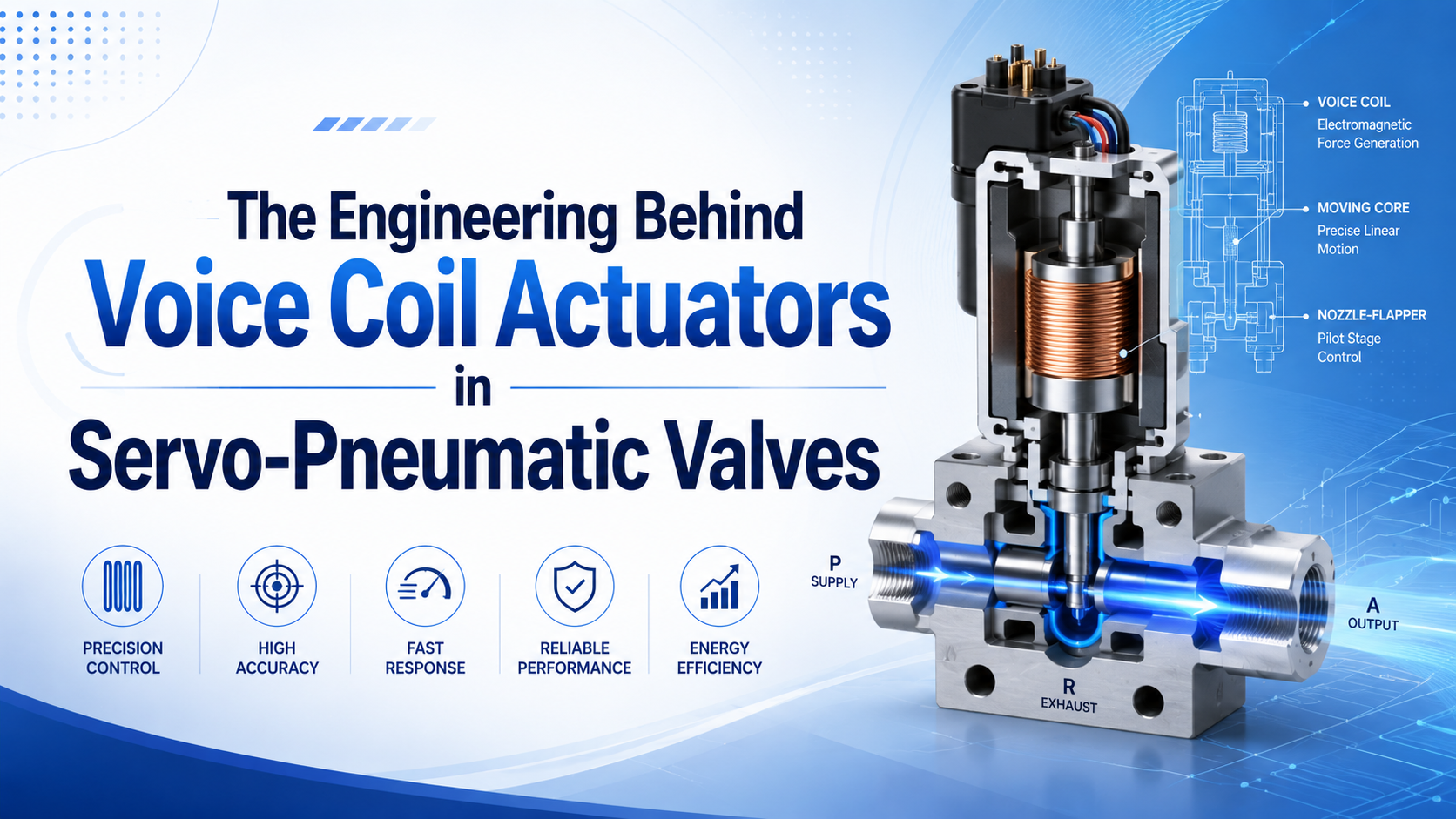
A voice coil actuator can move a pneumatic valve element directly and proportionally, but it does not position a cylinder by itself. The actuator converts coil current into linear force. The valve then converts spool or poppet displacement into a pressure or flow change, and the wider pneumatic system determines what the load actually does.
That distinction matters. A fast electrical current loop, a responsive valve spool, and an accurate machine axis are three different engineering results. Each needs its own measurement, tolerance, and test conditions.
Key Takeaways
- Festo specifies up to 30 Hz for one moving-coil pressure-regulator family, not a universal sub-millisecond value.
- Voice-coil force is proportional to current only within the actuator’s defined magnetic and thermal range.
- Gas-flow force, friction, spring force, spool mass, leakage, pressure ratio, tubing, feedback, and tuning all affect the observed response.
What Does a Voice Coil Actuator Do Inside a Servo-Pneumatic Valve?
Festo describes its VPPI as a directly actuated proportional pressure regulator with a moving-coil actuator, nested current, motion, and pressure control, and dynamics up to 30 Hz (Festo VPPI documentation, 2026). The voice coil supplies controllable force to the valve’s moving element; it is not the complete pneumatic control loop.
A voice coil actuator is a short-stroke electromagnetic force device. A permanent-magnet assembly establishes magnetic flux across an air gap. Current in the moving coil produces an axial force, and that force moves a spool, poppet, flexure, or another metering element. Reversing current can reverse force in a bidirectional design.
The useful engineering chain is:
electrical command -> current controller -> coil force -> valve-element position
-> metering-area change -> mass-flow or pressure change -> pneumatic load response
Each arrow can introduce saturation, delay, hysteresis, noise, or uncertainty. A coil can move quickly while a large downstream volume pressurizes much more slowly, so quoting only the electromechanical delay would hide the dominant pneumatic delay. What result does the process actually need: valve opening, regulated pressure, cylinder velocity, or final position?
A direct-drive arrangement connects the electromagnetic actuator closely to the metering element. It can avoid a pneumatic pilot stage and its bleed flow, but “direct drive” does not mean “no moving parts.” The valve still has a moving coil or armature, guidance, a spool or poppet, seals or precision clearances, springs, and pneumatic surfaces exposed to pressure and flow.
For the broader distinction between pressure, flow, and directional functions, use the proportional-valve selection guide. This article stays inside the electromechanical valve stage.
Voice-Coil Force and Spool Motion
A 2019 study developed a voice-coil direct-drive pneumatic servo valve for 10 MPa gas pressure and reported 5 μm steady spool-position accuracy under its experimental conditions (Gao et al., Precision Engineering, 2019). Those numbers describe a research valve’s internal spool loop, not the position accuracy of a connected pneumatic axis.
For a voice coil operating in its intended magnetic region, the practical force relationship is:
Here, is electromagnetic force in newtons, is the actuator force constant in newtons per ampere, and is coil current in amperes. The relationship is a useful design model, not permission to assume perfect linearity at every stroke, temperature, or current.
The familiar conductor expression explains the physical origin, where represents magnetic flux density, is current, and is active conductor length oriented to produce axial force. An assembled voice coil uses many conductor segments within a three-dimensional magnetic circuit, so its measured force constant is normally more useful than multiplying nominal magnet and winding values.
Current control matters because coil resistance changes with temperature. A fixed voltage does not guarantee fixed current. When the winding warms, resistance rises and current can fall unless the drive electronics compensate. A current-regulated amplifier therefore gives the force-producing stage a more repeatable command, within its voltage and thermal limits.
The valve may also close an internal position loop around the spool or poppet. A position sensor measures the moving element, the controller compares it with the commanded opening, and the current loop corrects the error. This architecture can reduce sensitivity to spring force, friction, and pressure disturbance, but only inside the controller’s stable bandwidth and available force margin.
The most useful voice-coil specification is not “high precision.” It is the usable map from command to current, current to force, force to valve position, and valve position to flow or pressure. A weak link in any one map limits the complete valve.
Which Forces Limit Voice-Coil Valve Spool Position?
In one experimental high-pressure pneumatic servo valve, an aerostatic bearing reduced measured static friction from 15 N to 4.4 N; the same study treated nonlinear gas-flow force as a control disturbance (Gao et al., 2019). The voice coil must overcome the net force on the moving assembly, not merely its mass.
A simplified axial force balance is:
In this relationship:
- is the effective moving mass of the coil, shaft, spool, and attached parts.
- is valve-element displacement; and are velocity and acceleration.
- represents effective damping.
- is the spring rate when a return or centering spring is present.
- is the signed gas-flow force for the valve position and port pressures.
- is the signed seal, guide, and spool-sleeve friction, normally opposing motion.
- collects signed preload, gravity, pressure imbalance, and other defined bias forces.
The positive direction must be defined before using the equation. Flow force can change with valve opening, pressure ratio, and flow direction; Coulomb friction changes sign when velocity reverses. The signed functions prevent those disturbances from being treated as fixed negative loads.
The equation shows why a small no-flow bench test cannot establish performance at rated pressure and flow. Once the valve meters compressible gas, jets and pressure distribution can push on the spool. A 2013 study of a high-pressure voice-coil pneumatic servo valve found that steady gas-flow force was a significant resisting disturbance and required geometry or control compensation (Energy Conversion and Management, 2013).
Pressure balance reduces the coil force required to hold a given opening. It does not remove every disturbance. Manufacturing tolerances, asymmetric metering edges, pressure transients, seal drag, contamination, and thermal expansion can still change the null position or command-to-flow curve.
Very small spool clearances present another tradeoff. They can reduce leakage, yet they increase sensitivity to contamination, surface condition, alignment, and thermal growth. The cited 2019 research valve used a clearance below 5 μm and explicitly linked that small gap to higher friction and wear risk. That is a valve-design result, not a recommended universal clearance.
Why Are Voice-Coil Valve Response-Time Claims Easy to Misread?
ISO 12238:2023 is a 17-page standard dedicated to measuring shifting time for electrically or pneumatically operated directional valves with two or three positions (ISO 12238:2023, 2023). Its existence illustrates the problem: “response time” needs a defined input, output threshold, pressure condition, valve state, and test method.
At least five times can appear in one servo-pneumatic application:
| Measurement | Start event | End event | What it proves |
|---|---|---|---|
| Electrical delay | Command change | Current reaches a stated band | Driver and coil electrical behavior |
| Valve-element delay | Command change | Spool or poppet begins or completes a stated movement | Electromechanical stage behavior |
| Pressure response | Setpoint change | Outlet or chamber pressure reaches a stated band | Valve, volume, leakage, and pneumatic path |
| Flow response | Command change | Measured mass flow reaches a stated band | Metering geometry and pressure-ratio behavior |
| Axis response | Motion command | Load reaches speed, position, or force tolerance | Complete valve, actuator, mechanics, sensor, and controller |
A frequency value is not a millisecond value in disguise. Bandwidth, natural frequency, switching frequency, PWM carrier frequency, and full-stroke shifting time describe different phenomena. Even two bandwidth measurements cannot be compared unless command amplitude, supply pressure, downstream condition, and acceptance threshold match.
One research on/off valve driven by a voice coil opened in 8.2 ms at 8 MPa supply and 240 V excitation (Applied Sciences, 2018). A different research valve reported 5 μm steady spool-position accuracy at 10 MPa, while Festo lists up to 30 Hz for a commercial moving-coil pressure regulator. None of those numbers replaces the others.
When a supplier says “sub-millisecond,” ask what crossed which threshold. Initial coil current, first detectable spool movement, a defined fraction of spool travel, regulated pressure settling, and loaded cylinder arrival are not interchangeable. A defensible comparison uses the same measured output and compatible test conditions.
For a separate treatment of ordinary directional-valve timing, see the pneumatic solenoid valve response-time guide.
How Do Nested Control Loops Change Valve Behavior?
Festo states that its VPPI regulates pressure through cascaded current, motion, and pressure control and provides an actual-value output; the documented family also offers 0-10 V or 4-20 mA setpoint variants (Festo VPPI documentation, 2026). Each loop controls a different physical quantity and runs within the limits of the loop inside it.
A typical nested architecture contains:
- Current loop: controls coil current and therefore approximate electromagnetic force.
- Valve-position loop: controls spool or poppet opening against friction, springs, and pneumatic disturbance.
- Pressure or flow loop: changes valve opening until the measured pneumatic output approaches its setpoint.
- Machine-motion loop: uses external position or velocity feedback to correct the actuator and load.
Not every valve contains all four. A bare moving-coil valve may expose only coil terminals. A valve with integrated electronics may close current and spool-position loops. A proportional pressure regulator adds internal pressure feedback. A servo-pneumatic axis normally adds an external position sensor and controller.
Closing another loop can improve disturbance rejection, but it also introduces sampling, filtering, phase lag, gain limits, and possible oscillation. The inner loop must usually be faster than the outer loop it supports. If a machine controller tries to correct position faster than the valve and chamber pressure can respond, the command can saturate or hunt.
The complete pneumatic axis still includes compressible chamber volume, tube volume, load-dependent force, seal friction, guidance, and structural compliance. A precise spool sensor cannot measure tooling flex. A fast pressure loop cannot correct a loose carriage guide. External position feedback must reference the process datum that determines whether the operation passed.
The feedback-sensor integration guide explains that datum boundary. The servo-pneumatic positioning guide covers the outer motion loop.
Coil Temperature and Continuous-Current Limits
Festo lists 24 V nominal operation and maximum electrical power consumption of 14.5 W for the documented VPPI family (Festo VPPI datasheet, 2026). Those are model-family values, but they expose a general constraint: a voice coil converts part of its electrical input into heat, and continuous force is thermally limited.
Copper loss follows:
Here, is winding heat generation in watts, is RMS coil current in amperes, and is winding resistance in ohms at the operating temperature. For PWM drive, use the current waveform’s RMS value for thermal screening, not only its peak.
Peak current may be available briefly for acceleration or disturbance rejection. Continuous current must keep the winding, insulation, magnet, sensor, electronics, and surrounding valve body within their rated temperatures. Mounting surface, airflow, enclosure, ambient temperature, duty cycle, and nearby heat sources all change the thermal result.
What happens when a valve must hold against a steady spring or flow force? The coil may require continuous current even though the spool is not visibly moving. The statement “power is used only during motion” is therefore not a safe general rule for a voice-coil valve.
Temperature also changes resistance, magnet strength, dimensions, friction, and electronic offset. A cold calibration can drift after the valve reaches thermal equilibrium. Test command-to-position and command-to-output behavior at stabilized operating temperature, especially when the tolerance depends on small openings near null.
How Should Engineers Specify and Test a Voice-Coil Servo-Pneumatic Valve?
The 2018 high-pressure voice-coil on/off valve reached an 8.2 ms opening time only under specified 8 MPa supply and 240 V excitation (Applied Sciences, 2018). A useful voice-coil valve specification therefore binds every dynamic number to command amplitude, pressure, downstream load, temperature, measurement point, and pass threshold.
Start with the controlled output. Do you need variable flow, regulated pressure, a bidirectional directional function, or an external motion axis? Then document the valve’s role in that system.
| Specification group | Required evidence |
|---|---|
| Pneumatic function | Port function, normal state, fail state, pressure range, medium, filtration, leakage, and flow curves |
| Electrical drive | Supply, command type, current range, peak and continuous current, PWM limits, grounding, and connector |
| Mechanical stage | Stroke, force constant, moving mass, centering method, position sensing, and allowable side load |
| Static control | Null shift, threshold, hysteresis, repeatability, linearity, pressure sensitivity, and temperature drift |
| Dynamic control | Step amplitude, rise and settling definitions, overshoot, bandwidth, phase, pressure, and downstream volume |
| Environment | Ambient and medium temperature, ingress protection, vibration, shock, contamination, and mounting orientation |
| Diagnostics | Actual current, valve position, pressure or flow feedback, saturation, temperature, and signal-loss indication |
Commission the valve in layers. First verify wiring, current polarity, command scaling, and the defined power-off position at a safely limited pressure. Next record valve position against increasing and decreasing commands. Then introduce normal pressure and flow, followed by the real downstream volume and load.
In our experience, the most revealing commissioning record contains four synchronized traces: command, coil current, valve-element position, and controlled pressure or flow. If the machine also moves, add external position and point-of-use pressure. Those traces separate a current limit from spool friction, pneumatic delay, supply pressure loss, or outer-loop tuning.
Use controlled boundary tests rather than improvised faults:
- minimum and maximum approved supply pressure;
- minimum, nominal, and maximum downstream volume or load;
- cold start and stabilized operating temperature;
- increasing and decreasing commands through the low-opening region;
- command loss, power loss, sensor fault, and pressure restoration;
- rated exhaust hardware and the maintenance limit for contamination.
Define abort limits before testing. A valve’s normal control function is not automatically a safety function. Loads that can fall, drift, eject a part, or trap hazardous pressure need protection defined by the machine risk assessment.
If dynamic pressure falls during testing, use the pressure-drop troubleshooting guide before retuning the controller.
When Is a Voice-Coil Valve the Right Engineering Choice?
The documented VPPI family spans pressure ranges from -0.1 to 1.2 MPa and lists dynamics up to 30 Hz, showing that a moving-coil design can serve real proportional pneumatic control without implying one universal performance class (Festo VPPI documentation, 2026). Application fit depends on the required output and verified operating envelope.
A voice-coil valve is a strong candidate when the application needs bidirectional or continuously variable force on a short-stroke valve element, low moving mass, direct electronic control, and useful internal feedback. It can suit dynamic pressure regulation, proportional flow, force control, and servo-pneumatic motion when the complete loop is engineered for those tasks.
It is not automatically the best choice when:
- the process needs only two end states and a standard directional valve meets the timing requirement;
- holding force would demand excessive continuous coil current or heat;
- contamination, washdown, vibration, or temperature exceeds the assembly rating;
- the valve’s low-opening leakage or null behavior cannot meet the process requirement;
- the machine needs stiffness, multi-axis path control, or tolerance better served by an electric servo axis;
- no supplier data defines the claimed response under comparable conditions.
Compare alternatives by function, not by buzzword. A proportional solenoid may offer a simpler force-stroke characteristic for a modest dynamic target. A piezoelectric pilot can use very little steady electrical power but has different stroke, voltage, contamination, and amplification constraints. A two-stage valve can control higher flow with a small pilot actuator, while adding pilot dynamics and bleed or leakage considerations.
The correct decision comes from the error and response budget. If the process tolerance applies to a rodless-cylinder carriage or tool, include guidance, load, position feedback, chamber volume, pressure stability, and controller behavior. The pneumatic-versus-electric precision guide can help when the real choice is between complete motion architectures.
Voice Coil Servo-Pneumatic Valve FAQs
Festo publishes a 30 Hz maximum dynamic value for one moving-coil pressure-regulator family, while a separate 10 MPa research valve reports 5 μm steady spool-position accuracy (Festo, 2026; Gao et al., 2019). These FAQs keep component, valve, and machine results separate.
Does a voice coil actuator give a pneumatic valve infinite resolution?
No. Coil current may be continuously adjustable, but usable valve resolution is limited by the driver, current sensing, magnetic force variation, friction, spool-position sensing, noise, controller quantization, leakage, and metering geometry. Specify the smallest repeatable change in the controlled pressure or flow under stated conditions, not an abstract “infinite” electrical resolution.
Does a valve bandwidth rating prove sub-millisecond response?
No. A bandwidth or natural-frequency rating does not directly equal full-stroke shifting time, pressure settling time, or loaded-axis arrival time. Check command amplitude, pressure, downstream volume, measured output, threshold, and settling band. ISO 12238:2023 standardizes shifting-time measurement for applicable pneumatic directional valves, but other outputs need their own definitions.
Does direct voice-coil drive eliminate valve wear?
No. Direct drive can remove a pneumatic pilot stage and its related parts, but the assembly still contains moving guidance, a spool or poppet, springs, precision clearances, and sometimes seals. Friction, contamination, impact, side load, and thermal growth remain relevant. Use the exact manufacturer’s air-quality, service, and life-test conditions.
Can the voice-coil valve’s spool accuracy be used as cylinder positioning accuracy?
No. Spool accuracy describes the valve element, while cylinder or carriage accuracy also includes pressure and flow dynamics, air compressibility, tubing volume, seal friction, load changes, mechanical guidance, sensor datum, controller tuning, and structural compliance. Validate final position at the process datum with the production load and motion profile.
What data should an RFQ include for a voice-coil pneumatic valve?
Provide the pneumatic function, supply and downstream pressure range, required flow or pressure profile, downstream volume, response definition, command interface, feedback needs, fail state, leakage limit, medium and ambient temperature, filtration, duty cycle, vibration, ingress protection, and acceptance test. State which output must meet the tolerance and where it is measured.
Sources and technical references
- Festo VPPI proportional pressure regulator documentation, 2026.
- ISO 12238:2023, Pneumatic fluid power — Directional control valves — Measurement of shifting time, 2023.
- Gao et al., Research on a high-accuracy and high-pressure pneumatic servo valve with aerostatic bearing, 2019.
- Li et al., Evaluation and compensation of steady gas flow force on a high-pressure electro-pneumatic servo valve, 2013.
- Nie et al., Development of a high-pressure pneumatic on/off valve direct-driven by a voice coil motor, 2018.