

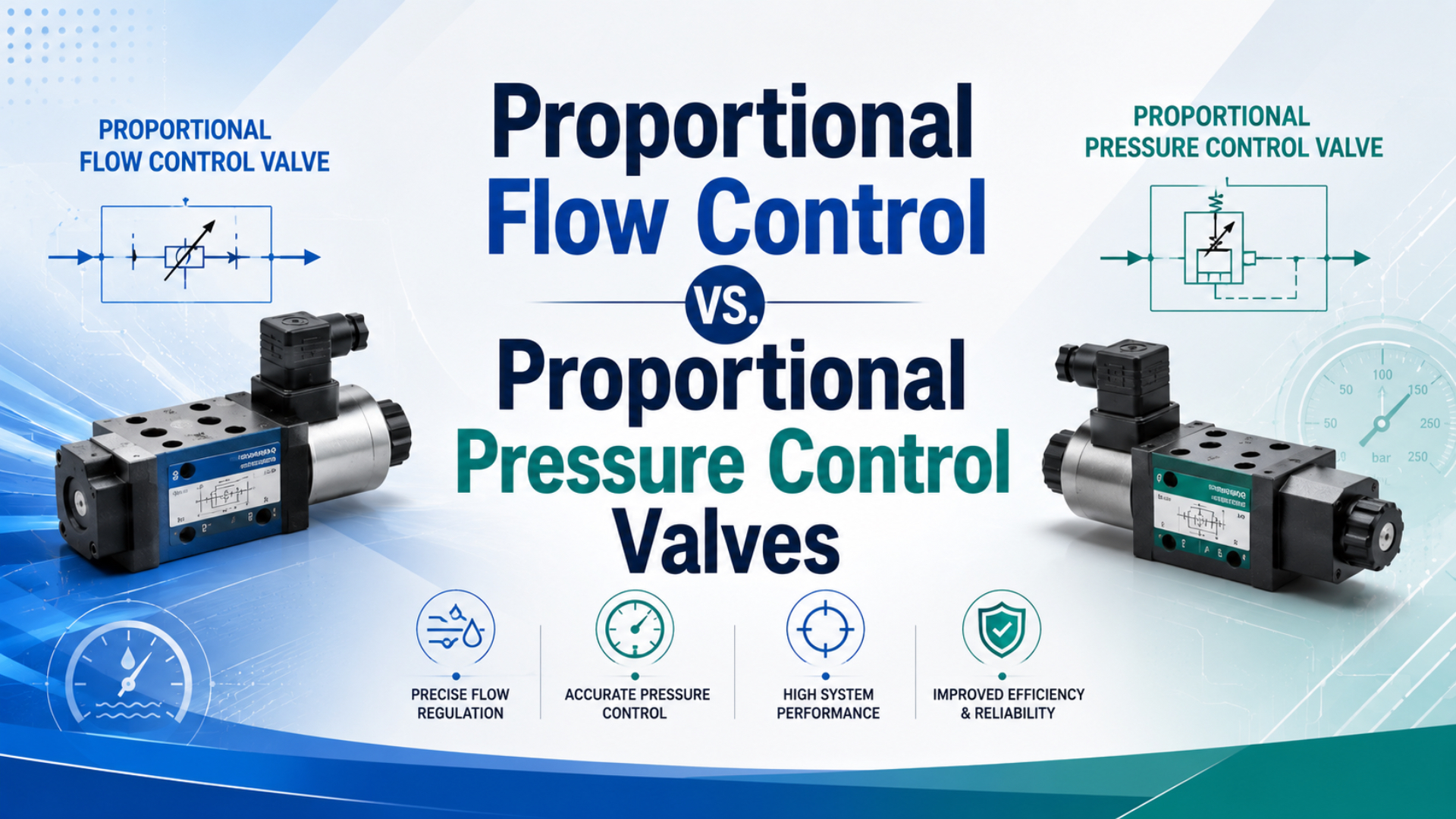
Choose a proportional flow valve when the commanded variable is airflow, and choose a proportional pressure regulator when the commanded variable is downstream pressure. Neither device, by itself, guarantees cylinder speed, position, or contact force. Those process results also depend on pressure differential, actuator area, load, exhaust backpressure, air volume, and feedback location.
The most useful selection question is not “Which proportional valve is more accurate?” Ask what must remain stable when the load or supply changes, where that variable is measured, and what the controller will correct. A current-controlled orifice, a closed-loop mass-flow controller, and a pressure regulator can all accept an analog command while performing three different jobs.
Key Takeaways
- SMC shows the same 150 mA command producing about 65 or 40 L/min when valve pressure differential changes.
- Flow command, measured flow, cylinder speed, downstream pressure, and contact force are different variables.
- Specify the feedback sensor, disturbance tests, fail state, and acceptance limits, not just the signal type.
What Is the Fundamental Difference?
Festo separates proportional devices by controlled variable: flow-control valves regulate flow rate, while pressure regulators regulate pressure. Its VEMD flow valve adds a thermal sensor and closed loop, whereas its MPYE converts an analog input into spool position (Festo proportional valves, retrieved 2026). That architecture distinction comes before catalog accuracy.
Proportional flow valve is a continuously adjustable pneumatic final control element that changes an opening or directly regulates measured airflow. Proportional pressure regulator is a valve-and-sensor assembly that adjusts supply or exhaust flow to hold a downstream pressure setpoint. Closed-loop flow controller is the flow-sensing version that corrects its opening from measured flow error.
| Device architecture | Command ultimately sets | Internal feedback | What it directly controls | What still needs external feedback |
|---|---|---|---|---|
| Current-controlled proportional flow valve | Coil current and valve opening | Coil current, or none | Opening area; flow only under stated pressure conditions | Actual flow, cylinder speed, or position |
| Closed-loop flow controller | Flow setpoint | Mass- or volume-flow sensor | Measured flow within its specified range | Cylinder speed or position if load and chamber conditions matter |
| Proportional pressure regulator | Pressure setpoint | Downstream pressure sensor | Pressure at the sensor location | Contact force, position, or speed |
The word “proportional” describes how the valve responds across a command range; it does not identify the controlled variable. Before comparing two part numbers, draw the command, sensor, valve, pneumatic load, and process output as a loop. If the sensor is missing from that drawing, the claimed regulation is open loop at that point.
For the component-level mechanisms, see the focused guides to proportional flow control in rodless-cylinder systems and electro-pneumatic pressure regulators.
Why Doesn’t a Proportional Flow Command Guarantee Speed?
SMC’s PVQ catalog shows why command is not flow: at 150 mA, an example changes from about 65 to 40 L/min as pressure differential changes. The same catalog states that flow decreases when outlet pressure rises, even if inlet pressure and current remain unchanged (SMC PVQ).
An open-loop proportional flow valve normally maps the electrical command to current and valve opening. Actual flow then depends on the upstream pressure, downstream pressure, gas temperature, valve geometry, and whether the flow is choked. A convenient incompressible-liquid square-root equation is not a valid general compressed-air sizing law.
For a cylinder chamber, the first-order kinematic relationship is:
Here, is piston velocity, is the actual volumetric flow entering or leaving the cylinder chamber at chamber conditions, and is that chamber’s effective piston area. Catalog flow quoted in standard litres per minute is referenced to standard conditions, so it cannot be inserted into this equation without the appropriate pressure and temperature conversion.
The equation also omits air compression and chamber filling. During acceleration, part of the incoming mass flow raises pressure before it produces motion. The load determines the pressure needed to overcome opposing force; exhaust restriction determines backpressure. For example, the same opening can drive different cylinder speeds before and after a payload change because chamber pressure and valve pressure differential have changed.
Use three different specifications:
- Valve command repeatability describes the input-to-opening behavior.
- Flow accuracy requires a flow sensor and a defined flow reference condition.
- Speed accuracy requires a velocity or position measurement over a stated load and stroke region.
If the speed tolerance is contractual, close the loop with position or velocity feedback. Festo makes the boundary explicit: its MPYE is a position-controlled spool valve, but precise actuator positioning requires an external position controller and displacement encoder (Festo proportional valves, retrieved 2026).
Use the Cv Flow Calculator to compare catalog flow coefficients and defined pressure-drop cases. Then validate compressed-air flow with the manufacturer’s gas-flow data and the real inlet/outlet pressure range; the pneumatic flow-control sizing guide explains that second step.
Why Doesn’t a Pressure Setpoint Guarantee Force?
SMC specifies ITV electro-pneumatic regulators with linearity of ±1% full scale or less and hysteresis of 0.5% full scale or less, depending on model and test conditions (SMC ITV). Those figures describe regulated pressure behavior, not the final force at a workpiece.
A proportional pressure regulator compares its pressure setpoint with an internal pressure sensor, then supplies or exhausts air to reduce the error. It regulates pressure at that sensor location. Tubing loss, local volume, chamber pressure, exhaust backpressure, seal friction, mechanism geometry, and contact conditions remain outside the regulator’s pressure loop.
For a double-acting single-rod cylinder, a more useful static force balance is:
Here, is cap-end chamber pressure, is full piston area, is rod-end chamber pressure, is rod-side annular area, and combines friction and external opposing forces. Use consistent pressure and area units. The equation describes a static force balance; dynamic acceleration adds inertial terms.
Regulating the supply to the cap end does not eliminate rod-end backpressure. A meter-out valve, undersized exhaust, silencer, or directional valve can raise and reduce net extension force. The backpressure guide covers this often-missed term.
Pressure regulation is an indirect force strategy. It works when cylinder area, opposing pressure, friction, linkage ratio, and contact geometry are sufficiently stable. If the process acceptance criterion is actual contact force, place a load cell or force sensor in the relevant load path and close the loop around that measurement.
Use the Cylinder Force Calculator to estimate push and pull force from bore, rod diameter, pressure, and allowances. Treat its result as a sizing estimate, then instrument the process if force accuracy is a production requirement. The pressure-differential force guide provides the underlying area and pressure relationships.
Disturbances That Separate the Three Control Architectures
Bürkert’s Type 8605 accepts 40 to 2,000 mA output and uses internal current control to compensate for coil heating, but it describes the fluid result as a valve-opening effect unless a process sensor closes another loop (Bürkert Type 8605, retrieved 2026). Current stability, flow stability, and process stability are therefore separate claims.
| Disturbance | Current-controlled orifice | Closed-loop flow controller | Pressure regulator |
|---|---|---|---|
| Coil temperature changes | Current control can reduce coil-current drift | Flow loop corrects remaining flow error within limits | Pressure loop corrects resulting pressure error within limits |
| Supply pressure changes | Flow normally changes | Flow loop adjusts opening if authority remains | Outlet pressure is corrected if supply margin and capacity remain |
| Downstream pressure changes | Flow normally changes | Flow loop adjusts opening within its differential-pressure envelope | Regulator responds to pressure error, not to a flow target |
| Cylinder load changes | Chamber pressure and speed can change | Measured flow may remain stable while speed transient still changes | Measured pressure may remain stable while motion or contact force changes |
| Exhaust backpressure changes | Speed and net force can change | Inlet flow control may not correct the exhaust-side disturbance | Supply-pressure control does not directly remove opposing chamber pressure |
| Leakage or changing demand | Commanded opening does not restore a process variable | Controller adds opening to recover measured flow within capacity | Regulator adds supply flow to recover measured pressure within capacity |
No loop can correct a disturbance after the actuator saturates. A fully open valve cannot provide more flow, and a regulator cannot hold outlet pressure when supply pressure, inlet capacity, or exhaust capacity is insufficient. Review control authority across the worst operating corner, not only at the nominal point.
Response time also belongs to the complete pneumatic volume. Catalog valve response may be fast while a long tube and large chamber fill slowly. Conversely, a small local volume can respond quickly but oscillate if controller tuning, sensor placement, and pneumatic compliance interact poorly.
When Do You Need Flow, Pressure, or Both?
Festo lists 0–10 V and 4–20 mA interfaces for proportional pressure products, while its VEMD uses an integrated thermal flow sensor for closed-loop mass-flow regulation (Festo proportional valves, retrieved 2026). Shared signal formats do not make the devices interchangeable; the required machine result decides the architecture.
Choose the simplest loop that measures the variable you must hold:
| Primary requirement | Starting architecture | Add external feedback when |
|---|---|---|
| Adjustable blow-off, dosing, or purge flow | Closed-loop flow controller | The downstream process quality, not flow itself, is the acceptance variable |
| Repeatable cylinder speed over a narrow, stable load range | Proportional orifice or closed-loop flow controller | Load, supply, stroke region, or backpressure changes exceed the speed tolerance |
| Pressure recipe or compliant clamping level | Proportional pressure regulator | Actual contact force or part deformation must be guaranteed |
| Position profile | Proportional directional/flow valve | Always use position feedback when position is contractual |
| Force profile at contact | Pressure regulator as the pneumatic final element | Use a force sensor when actual force is contractual |
| Fast approach plus limited contact force | Flow/position control for approach, pressure/force control for contact | Coordinate modes and define a safe, stable transfer condition |
The “both” case is not solved by placing two valves in series without a control plan. For example, a handling axis can use position feedback for fast approach, then transfer authority to a force loop after verified contact. Define the transition trigger, setpoint ramps, and response to implausible pressure, position, or force feedback.
Data-Sheet Comparison Before Selection
SMC lists the PVQ30 with a 0–100 L/min flow range, repeatability of 3% or less, and hysteresis of 10% or less, while selected ITV regulators specify ±1% full-scale linearity and 0.5% full-scale hysteresis (SMC PVQ; SMC ITV). These numbers describe different variables and test methods, so they are not a head-to-head accuracy ranking.
Compare flow-device data at the stated gas and pressure conditions:
- Controlled quantity: current, opening, volumetric flow, or mass flow
- Flow reference: standard, normal, or actual conditions, including reference temperature and pressure
- Inlet and outlet pressure range, minimum differential pressure, and choked-flow boundary
- Rated flow range, controllable minimum, leakage, hysteresis, repeatability, and response definition
- Signal type, command impedance, monitor output, and loss-of-signal behavior
- Duty cycle, coil heating, ambient temperature, contamination tolerance, and mounting orientation
Compare pressure-regulator data against the actual pneumatic volume and demand:
- Outlet-pressure range, supply-pressure margin, and proof pressure
- Linearity, hysteresis, repeatability, sensitivity, and the denominator used for each percentage
- Supply and exhaust flow capacity, relieving or non-relieving behavior, and pressure droop under flow
- Internal sensor location, external-sensor option, monitor output, and response test volume
- Residual pressure after command loss and behavior after supply interruption
- Filter requirement, permitted lubricants, electrical interface, and environmental rating
ISO 6358-1 defines steady-state methods for pneumatic components using compressible gases and covers both fixed and variable flow paths (ISO 6358-1:2013, confirmed 2022). Ask suppliers for the test conditions and characteristic curves that match your operating region instead of comparing one maximum-flow number across unlike catalogs.
RFQ and Acceptance-Test Checklist
ISO 4414 covers design, installation, operation, and maintenance requirements for pneumatic systems, not only component nameplate data (ISO 4414:2010, confirmed 2021). A proportional-valve RFQ should therefore specify the complete operating envelope and at least 3 disturbance tests: minimum supply, maximum load or demand, and loss of command or power.
Include these RFQ inputs:
- State the contractual variable and tolerance: flow, pressure, speed, position, or force.
- Define minimum, nominal, and maximum inlet and outlet pressure.
- Define normal, peak, and minimum controllable flow with reference conditions.
- Provide actuator bore, rod diameter, stroke, orientation, moving mass, load range, tubing dimensions, and exhaust restrictions.
- Identify every feedback sensor, its location, range, accuracy, update rate, and controller ownership.
- Specify command and monitor signals, electrical supply, communications, fail state, and reset sequence.
- State ambient temperature, air quality, duty cycle, ingress protection, and permitted mounting orientation.
- Require the supplier’s ordering code, circuit symbol, flow/pressure curves, response definition, and test conditions.
An acceptance test must measure the result at the correct point. For flow control, log command, actual flow, inlet pressure, outlet pressure, and process response. For pressure control, log setpoint, pressure at the regulator, chamber or process pressure, flow demand, and force if force matters.
Test the cross-variable disturbance deliberately. Change outlet pressure while holding a flow command, then change flow demand while holding a pressure command. Those two tests expose whether a proposed device regulates the claimed variable, merely positions an orifice, or runs out of control authority at the edge of the operating envelope.
Record settling time, overshoot, steady-state error, hysteresis direction, and the state after command loss. Repeat at hot and cold operating conditions when coil temperature or gas temperature can shift performance. Pass/fail criteria should use measured process variables, not a claim that the analog output “looked stable.”
Proportional Valve Selection FAQs
SMC publishes proportional flow examples from 0–6 L/min for PVQ10 and 0–100 L/min for PVQ30, while its ITV family covers several pressure ranges up to 0.9 MPa depending on model (SMC PVQ; SMC ITV). Selection must start with the controlled variable and operating envelope, not the shared “proportional” label.
Can one proportional valve control both speed and force?
A proportional valve can serve as the final element in different external control loops, but one internal loop cannot regulate two independent variables simultaneously. A machine can use motion control during approach and force control after contact. The controller must define the transfer condition, loop authority, limits, and failure response.
Is a proportional flow valve the same as a mass-flow controller?
No. A proportional flow valve may only map current to opening, leaving actual flow dependent on pressure and temperature. A mass-flow controller includes a flow sensor and closes the loop around measured mass flow. Confirm the sensor, reference conditions, control range, response, and pressure envelope in the data sheet.
Will a proportional pressure regulator maintain constant cylinder force?
It maintains pressure at its sensor within specified limits, not force at the workpiece. Cylinder force also depends on effective piston area, opposing chamber pressure, friction, linkage geometry, and acceleration. Use pressure regulation for an indirect force estimate; add a load cell and force loop when actual force is contractual.
Which valve should control cylinder speed under changing loads?
Start with proportional flow control, but measure cylinder motion if speed tolerance must hold across a wide load range. A load change alters chamber pressure and pressure differential, which can change both open-loop flow and acceleration. Position or velocity feedback lets the controller correct the actual motion instead of assuming flow equals speed.
What is the most important proportional-valve acceptance test?
Apply the disturbance the selected architecture is expected to reject. For a flow device, vary inlet or outlet pressure while recording measured flow. For a pressure regulator, vary downstream demand while recording outlet pressure. Include command loss, saturation, settling time, hysteresis direction, and the real process result in the pass/fail record.
Sources and technical references
SMC: PVQ Series Compact Proportional Solenoid Valve, current-to-flow behavior, pressure-differential examples, flow ranges, repeatability, and hysteresis. Retrieved 2026-07-22.
SMC: ITV Series Electro-Pneumatic Regulator, pressure ranges, linearity, hysteresis, sensitivity, flow, and response conditions. Retrieved 2026-07-22.
Festo: Proportional Valves Overview, flow-valve and pressure-regulator functions, VEMD integrated flow loop, MPYE spool-position control, and VPPE interfaces. Retrieved 2026-07-22.
Bürkert: Type 8605 Digital Control Electronics, PWM output, internal coil-current control, 40–2,000 mA range, and valve-opening behavior. Retrieved 2026-07-22.
ISO: ISO 6358-1:2013, steady-state test methods for pneumatic components using compressible gases. Retrieved 2026-07-22.
ISO: ISO 4414:2010, general rules and safety requirements for pneumatic systems and components. Retrieved 2026-07-22.