

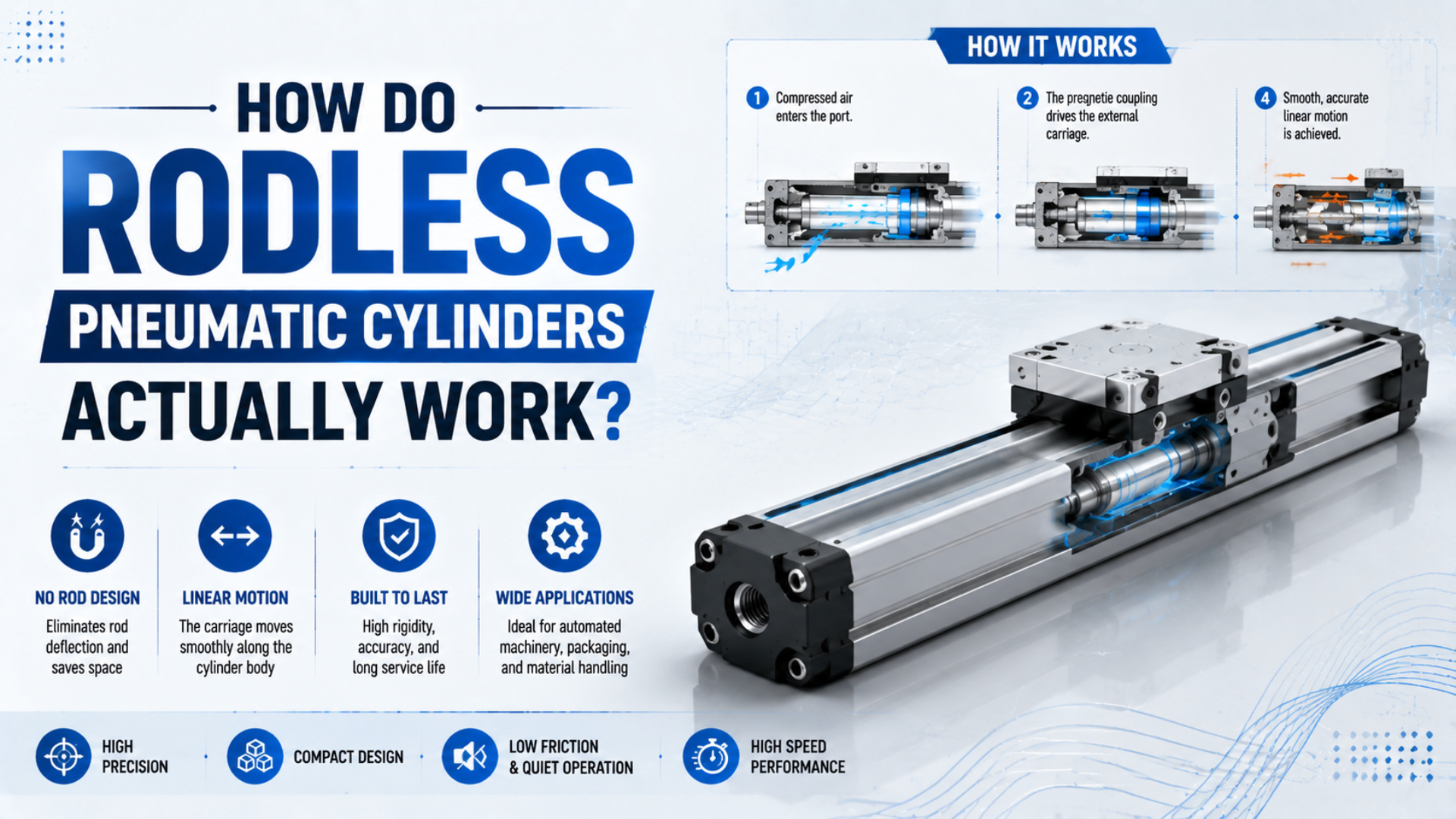
A rodless pneumatic cylinder is an actuator that turns pressure into linear motion inside a sealed tube, then transfers that motion to an external carriage. Magnets can carry the motion across an unbroken tube wall, while a mechanical yoke passes through a sealed longitudinal slot. Either way, the load moves beside the tube instead of on an extending piston rod.
This article follows one complete operating cycle. It starts with the directional valve, traces chamber pressure and piston thrust, separates the coupling path from the guide path, and ends with exhaust control, cushioning, and sensing. For definitions, product types, and general selection, use the broader rodless cylinder guide.
Key Takeaways
- One stroke contains six linked events: switching, filling, thrust, coupling, guidance, and stopping.
- Magnetic coupling crosses a closed tube wall; a mechanical yoke passes through a band-sealed slot.
- Cylinder force moves the piston, while the carriage guide carries external side loads and moments.
- Flow controls speed, and cushioning manages only the final part of the stroke.
What Happens When the Directional Valve Switches?
Parker identifies the OSP-P as a double-acting rodless cylinder with an air connection at each end cap. Switching the directional valve supplies one chamber while opening the opposite chamber to exhaust. That pressure difference starts the piston moving; reversing the two flow paths reverses the stroke (Parker OSP-P Operating Instructions).
Before the command, both sides may still contain pressure. Valve action doesn’t pull the carriage directly. It changes the pressure boundary conditions at the two cylinder ports. Supply air must travel through the valve, manifold, fittings, and tube before the advancing chamber can build pressure. At the same time, displaced air must leave the retreating chamber.
That makes the first part of a stroke a filling and venting event. A valve spool can switch quickly while the piston responds slowly because pressure at the actuator ports takes time to change. Long tubes, small fittings, restricted silencers, and shared supply lines all alter that response.
Which pressure should be used to explain the motion? Use the pressure measured at the cylinder ports during travel. A regulator setting upstream is not proof of the differential acting across the piston when flow is high.
Pneumatic response separates the control signal from mechanical motion. For troubleshooting, record them as different events: sensor or PLC command, valve switching, chamber-pressure change, piston movement, and carriage movement. That sequence exposes faults that the phrase “cylinder is slow” hides.
How Does Chamber Pressure Create Piston Thrust?
Parker lists OSP-P extension forces from 47 to 3,010 N at 6 bar across its current bore range. Those are series-specific ratings, but the governing relationship is universal: net piston thrust comes from the pressure difference across the effective piston area, minus seal, bearing, and load-path resistance (Parker OSP-P Series).
For an ideal piston, the pressure-area relationship is:
Here, is ideal piston thrust in newtons, is the pressure difference across the piston in pascals, and is effective piston area in square meters. If pressure is expressed in megapascals and area in square millimeters, the result is also in newtons.
Piston thrust is the axial force available at the piston before coupling, guide, and external-load effects are applied. It should not be confused with permitted payload, allowable carriage moment, or usable process force.
Real output at the carriage is lower or differently limited. Seal friction and guide resistance subtract from the pressure-area result. Exhaust back pressure reduces . A magnetically coupled design also cannot transmit more than its catalog coupling limit, even if the piston could generate more pneumatic thrust.
For a mechanically coupled cylinder, the yoke provides a positive force path, but that doesn’t make the actuator lossless. Band flexing, wipers, piston seals, carriage bearings, and external misalignment still consume force. Use the exact catalog force and load tables after the first calculation.
The Cylinder Force Calculator can check pressure and piston area. Treat its result as the start of a model review, not as an allowable carriage load.
Two Coupling Paths: Magnetic and Mechanical
SMC’s CY3B magnetic series publishes holding forces from 19.6 N for a 6 mm bore to 2,256 N for a 63 mm bore. That range shows why magnetic transfer is a rated interface, not an unlimited connection. A mechanically jointed MY1B instead links the piston and slide table through the tube slot (SMC CY3B Catalog).
In a magnetic design, the internal piston carries one magnet set and the external carriage carries another. Their field crosses the nonmagnetic tube wall. When pressure moves the inner piston, magnetic attraction makes the outer carriage follow without opening the pressure tube.
Transmitted force must remain within the selected model’s holding-force limit. If inertia, obstruction, guide friction, or process load demands more, the piston can move relative to the carriage. Magnetic decoupling is this relative movement after the required transfer force exceeds the rated holding force. It is not a universal multiple of normal operating force.
For magnet arrangement, tube-wall effects, and recoupling limits, continue with the magnetic rodless cylinder technical guide.
In a mechanically jointed design, a yoke physically connects the piston to the external carriage through a longitudinal slot. Local band-routing geometry opens only the short region needed for the yoke and reseals the slot behind it. This force path is direct, but its pressure boundary is more mechanically involved.
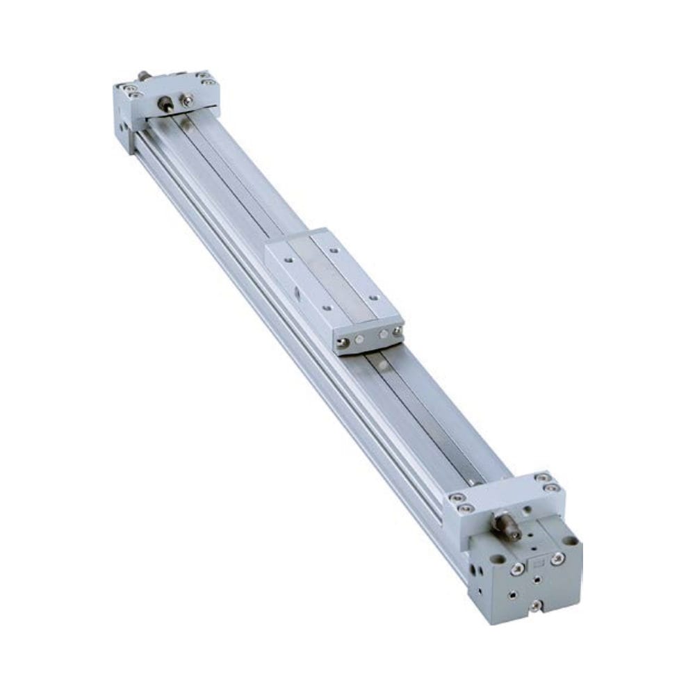
Which architecture is “stronger”? That question is incomplete. Compare catalog thrust, coupling or yoke limits, guide capacity, contamination protection, speed, stroke, orientation, and failure behavior. The magnetic versus mechanical coupling comparison handles that selection problem in detail.
Both architectures separate the pressure generator from the payload interface. Inside either design, the piston converts pressure into force. Coupling transfers axial motion. Carriage guides control how the external load is allowed to react. Treating those as three separate functions makes catalog limits easier to interpret.
How Does a Slotted Cylinder Open and Reseal Its Bands?
Parker’s OSP-P drawing identifies two stainless-steel components: outer band 11 and inner band 17. The inner band closes the pressurized longitudinal slot; the outer band protects it from the environment. Around the moving piston yoke, guides deflect and return both bands through controlled local paths (Parker OSP-P Operating Instructions).
Most designs never leave the full slot open. Almost all of the inner band remains seated along the tube. Only the short transfer zone inside the piston and carriage assembly is displaced so the yoke can pass. Behind that zone, guide geometry returns the band to its sealing path.
Direction matters. During rightward travel, the right side of the transfer zone opens and the left side reseats. During leftward travel, the roles reverse. The same continuous band performs both actions.
An outer band has a different job. It covers the exposed slot, passes through the carriage or wiper assembly, and reduces contamination entry. Damage to this visible strip does not automatically prove that the inner pressure band leaks.
Want the band geometry rather than the full operating cycle? The slit-type sealing mechanics guide explains the opening, reversing, and reseating path without duplicating it here.
Carriage Guides Carry Side Loads and Moments
SMC’s MY1 family uses five guide arrangements and evaluates combined moments with a utilization sum no greater than 1. This matters because piston thrust acts along the stroke axis, while an offset payload creates pitch, yaw, or roll moment at the carriage. The selected guide, not compressed air, must carry those reactions (SMC MY1 Catalog).
A basic rodless cylinder may require a separate linear guide. A guided version can integrate slide bearings, cam followers, or linear guides, but each configuration has its own load, speed, and moment envelope. The word “guided” doesn’t remove the need for a calculation.
For each load component, compare applied load or moment with the catalog allowance. When several components act together, follow the manufacturer’s combined-load equation. Do not approve the design because each value looks acceptable in isolation.
Payload offset is often the hidden variable. Moving the same mass farther from the guide increases the moment because its center of gravity has a longer lever arm. Acceleration and deceleration add dynamic forces, so a carriage that feels smooth during manual movement can overload its bearings during production.
Axial energy comes from the air path, but the guide path closes the external force loop into the machine frame. If the guide binds, pneumatic pressure rises and available thrust is spent overcoming friction. A force problem can therefore originate in mounting geometry rather than cylinder bore.
For detailed wear mechanisms, see how side loading affects cylinder bearings and seals.
Flow Control, Cushioning, and Sensors Complete the Stroke
SMC lists 15, 19, and 24 mm air-cushion strokes for selected MY1B 25, 32, and 40 mm bores. Those short zones show why cushioning isn’t the primary speed control for the full stroke. Meter-out flow control sets travel speed; the end cushion manages residual energy near the stop (SMC MY1B Catalog).
During most of the stroke, exhaust restriction governs how quickly the retreating chamber can empty. A meter-out valve creates controlled back pressure and tends to stabilize pneumatic motion under changing loads. An oversized opening can allow rapid acceleration; an undersized opening can waste pressure and slow the carriage.
An air cushion is an end-of-stroke exhaust restriction built into the actuator. As the piston enters that zone, a cushion seal restricts the remaining exhaust path. Trapped-air pressure rises and opposes motion, while an adjustable needle meters the final exhaust. The goal is a controlled arrival without rebound or hard impact.
For adjustment and impact energy, use the pneumatic air-cushioning guide. A separate meter-in versus meter-out control guide explains the circuit-level distinction.
A magnetic sensor mounted in the profile detects a magnet carried by the piston or carriage assembly. Its output reports that a switching position has been reached. It does not physically stop the payload, prove that the coupling stayed engaged, or measure the force available at the carriage.
What actually ends the cycle? The carriage decelerates within the permitted energy limit, the sensor changes state at its installed position, and the controller decides whether to hold, reverse, or start the next machine step. Those are related events, not one event.
How Can You Diagnose a Broken Motion Chain?
ISO 4414 covers pneumatic-system design, installation, adjustment, operation, and maintenance hazards. Before diagnosis, isolate stored energy and secure any load that could move. Once the machine is safe, inspect the six links in order instead of replacing seals or increasing pressure on guesswork (ISO 4414:2010).
| Observed symptom | Motion-chain check | Evidence to collect |
|---|---|---|
| No movement after command | valve switching and port pressure | electrical command, valve indication, pressure at both cylinder ports |
| Piston or carriage starts slowly | supply fill and exhaust restriction | dynamic port pressure, tube ID, fitting and silencer condition |
| Piston moves but carriage does not follow | magnetic coupling or mechanical yoke | model, coupling rating, obstruction, relative piston and carriage position |
| Motion is rough at repeatable positions | guide, slot, band, or tube condition | carriage position, travel direction, load offset, contamination |
| Hard impact at one end | speed and cushion adjustment | moving mass, measured speed, cushion setting, catalog energy limit |
| Sensor changes but mechanism is misplaced | sensor target and coupling state | sensor location, piston position, carriage position, controller timing |
Start with pressure on both sides of the piston. If the pressure differential is missing, the fault is upstream or in the exhaust path. If differential pressure exists but nothing moves, compare theoretical thrust with the load and check for mechanical binding.
For a magnetic cylinder, determine whether the piston and carriage are still aligned. Never drag the outer carriage into position against an unknown internal piston location while the circuit can pressurize. Follow the model’s recoupling procedure and holding-force limits.
For a slotted cylinder, note whether leakage or drag follows one physical coordinate, one travel direction, or the entire stroke. A position-specific symptom points toward local band, groove, tube, or guide damage. A direction-specific symptom suggests asymmetric routing, wiping, cushioning, or load reaction.
In our experience reviewing applications, a short event log is more useful than “intermittent cylinder fault.” Record the command time, both port pressures, first visible motion, carriage position, sensor transition, direction, load, and stop behavior. That evidence separates a control delay from a force-transfer or guide problem.
Rodless Pneumatic Cylinder FAQs: What Should Engineers Know?
Parker offers OSP-P strokes up to 6,000 mm, while SMC’s cited magnetic series spans 6 to 63 mm bores (Parker OSP-P Series; SMC CY3B Catalog). That range is why a working-principle explanation cannot supply universal force, speed, guide, or cushion limits. These five answers separate reusable principles from model-specific limits.
Does a rodless cylinder have an internal piston?
Yes. Pneumatic pressure still acts on an internal piston. What disappears is the external piston rod. A magnetic design transfers piston motion through the closed tube wall, while a mechanically jointed design connects the piston to the carriage through a sealed slot. The carriage is the external output member in both cases.
Can a rodless cylinder produce the same force in both directions?
Many double-acting rodless cylinders use the same effective piston area in both directions because no external rod subtracts annular area. Equal geometry doesn’t guarantee equal measured output, however. Port routing, exhaust back pressure, cushioning, seal resistance, guide friction, load direction, and model-specific coupling limits can make the two strokes behave differently.
What causes a magnetically coupled rodless cylinder to decouple?
Decoupling occurs when required transfer force exceeds the catalog magnetic holding force. Common contributors include excessive payload, acceleration, impact, guide binding, obstruction, or an unsuitable operating condition. The piston can continue moving internally while the carriage remains behind, so compare piston indication and carriage position before attempting the manufacturer’s recoupling procedure.
Does the sealing band carry the external load?
No. The inner band closes the pressure slot, and the outer band protects the opening. Axial motion passes through the piston yoke, while carriage bearings or an external guide carry permitted side loads and moments. Loading the band path through misalignment can still damage sealing, but the band is not the payload guide.
Are internal cushions enough for every high-speed application?
No. An internal air cushion has a model-specific stroke and energy envelope. It manages residual end-of-stroke energy after the main speed-control circuit has set travel velocity. If moving mass and speed exceed the catalog limit, reduce speed or add a correctly located external shock absorber rather than closing the cushion needle excessively.
Sources and technical references
- Parker OSP-P Operating Instructions, double-acting construction, air connections, piston yoke, bands, cushioning, and operating safety. Retrieved 2026-07-27.
- Parker OSP-P Series, bore range, stroke, force, pressure, temperature, sensing, and guide options. Retrieved 2026-07-27.
- SMC CY3B Catalog, magnetic holding-force ratings, bore range, speed range, and selection limits. Retrieved 2026-07-27.
- SMC MY1 Catalog, mechanical joint architecture, guide types, allowable load and moment selection, cushioning, and installation precautions. Retrieved 2026-07-27.
- SMC MY1B Cushion Data, cushion stroke and load-speed selection data. Retrieved 2026-07-27.
- ISO 4414:2010, pneumatic-system safety requirements for design, installation, adjustment, operation, and maintenance. Retrieved 2026-07-27.