

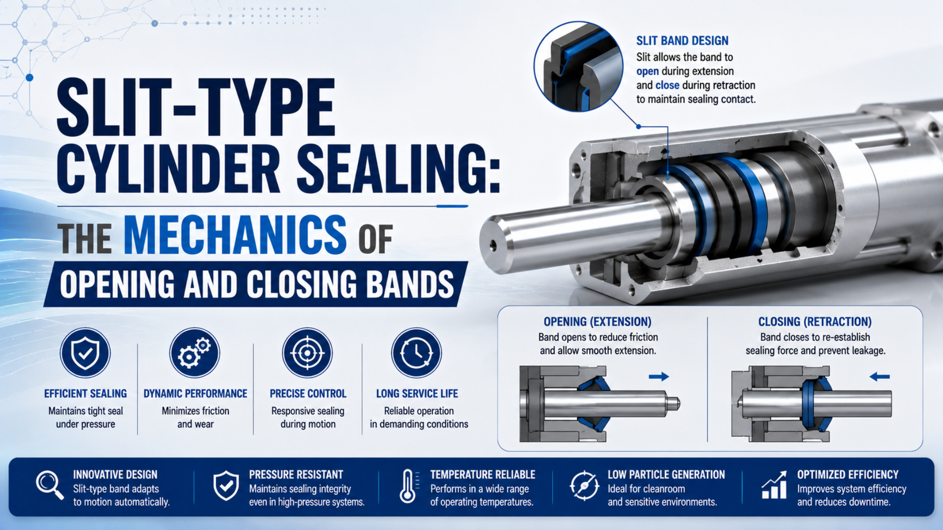
Slit-type cylinder sealing is the moving slot-closure system used in a mechanically coupled rodless cylinder. An inner sealing band closes the pressurized slot, while an outer cover or dust band protects the opening. The carriage lifts each band only through a short transfer zone and guides it back into position as the piston moves.
“Opening band” and “closing band” are useful descriptions of what happens around the moving carriage, but they are rarely the names of two fixed replacement parts. Ahead of the carriage, a band leaves its normal seat. Behind it, the same continuous band returns. Reverse the stroke and those two regions exchange roles.
Key Takeaways
- Parker identifies separate outer and inner bands as parts 11 and 17.
- Opening and closing describe local motion states that reverse with travel direction.
- Band path, groove condition, carriage guidance, contamination, and model-specific retention determine whether the slot reseals.
This distinction matters during diagnosis. A dented outer strip can expose the slot without causing pressure loss. A clean outer strip can hide a damaged inner pressure band. Before ordering either one, identify the actuator architecture, the failed function, and the exact manufacturer terminology.
Opening and Closing Are Motion States, Not Two Fixed Parts
Parker’s OSP-P instructions identify the outer sealing band as part 11 and the inner sealing band as part 17. Those numbers describe different layers, not permanently assigned “opening” and “closing” strips. Opening occurs ahead of the piston yoke; reseating occurs behind it, relative to the current travel direction (Parker OSP-P Operating Instructions).
Imagine the carriage moving from left to right. The local guide geometry raises the outer cover band and displaces the inner sealing band only where the mechanical connection passes through the slot. The band remains seated over the rest of the stroke. After the yoke passes, the guide path returns each band to its normal groove or contact surface.
Now reverse the cylinder. The region that was reseating becomes the opening side, and the former opening side becomes the reseating side. Nothing has been swapped during maintenance. The spatial roles changed because the motion direction changed.
That reversible relationship is the cleanest way to interpret the title. It also prevents a common spare-parts error: asking for an “opening band” when the drawing actually lists an inner sealing band, seal belt, outer sealing band, dust seal band, or cover strip.
Manufacturer vocabulary varies:
| Manufacturer example | Pressure-side component | External component | Local routing component |
|---|---|---|---|
| Parker OSP-P | Inner sealing band or I-band | Outer sealing band or O-band | Piston yoke and wiper cover |
| Festo DGC | Sealing band | Cover strip | Band reverser |
| SMC MY1 | Seal belt | Dust seal band | Slide table and model-specific guide structure |
The table is a translation aid, not proof of interchangeability. Width, edge form, material, end attachment, stroke allowance, groove geometry, and service procedure remain series-specific. For the broader replacement and leakage context, see the technical guide to rodless cylinder sealing bands.
The Two-Band Architecture
Festo’s DGC documentation separates the sealing band from the cover strip, while Parker separates parts 17 and 11. In both examples, one component manages the pressurized slot and another protects the exposed opening. The layers share a moving transfer zone, but they don’t have the same function (Festo DGC Documentation).
The inner component belongs to the pressure boundary. It must close the longitudinal slot everywhere except the short region captured inside the piston-yoke assembly. Its working surface, edges, and seating path therefore matter to leakage. Depending on the design, pressure can help hold the band against its seat, but the effective area and contact path come from the actual profile. A generic closing-force number would be misleading.
The outer component covers the slot from the environment. It encounters wipers, dust, fibers, chips, coolant residue, and handling damage. Parker calls this an outer sealing band; Festo calls it a cover strip; SMC uses the term dust seal band. “Sealing” in a parts list does not automatically mean that the visible strip is the compressed-air seal.
Why use two layers? The outer band can be optimized for exposure, wiping, and slot coverage, while the inner band can be optimized for pressure retention and repeated flexing. Combining every duty into one visible strip would make contamination damage and pressure sealing harder to manage.
The rodless cylinder dust-band guide covers the outer layer in more detail. This article stays with the mechanics that let both layers pass through a moving carriage without leaving the full slot open.
How Does the Piston Yoke Create a Local Opening?
Parker states that the piston yoke holds its two sealing bands in grooves. Festo’s DGC-HD procedure routes the sealing band and cover strip through separate lower and upper notches in a band reverser. These documented paths support controlled local deflection, not a universal 15-degree wedge or two-strip overlap model (Festo DGC-HD Repair Instructions).
The piston and external carriage need a mechanical connection through the longitudinal slot. That connection occupies the transfer zone. Inside it, shaped guides redirect the bands away from their normal seated paths, keep them clear of the yoke, then lead them back toward the slot.
Four features make the motion possible:
- A continuous band path. The strip bends through a designed radius instead of folding at a sharp hinge.
- Separate guide levels. The inner band and outer strip follow different notches, grooves, or surfaces so they don’t collide.
- A captured opening. The pressure-side opening remains inside the piston assembly rather than exposing an unrestricted slot to atmosphere.
- A controlled return. Exit geometry brings the band back toward its seat without requiring an external closing actuator.
Does every cylinder use visible rollers? No. Some drawings show wipers, guide surfaces, magnets, or reversers rather than a dedicated roller set. Treat “roller alignment force” as a model-specific feature only when the parts drawing shows it.
The band bends in two directions during each complete reciprocating cycle. It leaves its seated path as the carriage approaches, passes through the transfer zone, and returns behind it. That repeated flexing makes edge damage, creases, burrs, trapped particles, and incorrect routing more important than a generic material-hardness comparison.
Direction Reversal Changes the Roles
SMC’s MY1 catalog shows five standardized guide types across a family spanning 10 to 100 mm bores. Despite those variations, each double-acting mechanically jointed model supports travel in both directions. Therefore, the opening and reseating sides exchange roles whenever the slide reverses (SMC MY1 Catalog).
This explains why damage can appear directional. A burr or crease may enter the guide smoothly in one direction but catch when the path reverses. A wiper can also push debris toward one side of the transfer zone. If a hiss or drag appears only during one travel direction, record direction and carriage position instead of concluding that one fixed “closing band” has failed.
A useful diagnostic record has two coordinates: the carriage’s physical position along the stroke and its direction of travel. Position identifies a local slot or band defect. Direction helps identify asymmetric entry, exit, wiper, or guide behavior. Cycle count alone loses both clues.
Why Does the Band Reseat Behind the Moving Carriage?
Parker gives two explicit conditions for its OSP-P inner band: install it without pretension and without hanging loose. Consequently, reliable reseating depends on the designed groove and routing geometry. It doesn’t come from arbitrarily stretching the band until it feels tight (Parker OSP-P Maintenance Instructions).
As the band leaves the transfer zone, several model-specific effects can guide it home:
- Elastic recovery: The strip tends to recover from the local bend imposed by the yoke or reverser.
- Guide geometry: Exit surfaces aim the band toward its groove or sealing land.
- Pressure loading: On some inner-band profiles, chamber pressure supports contact against the pressure-side seat.
- Magnetic retention: SMC documents a seal magnet that attracts the dust seal band on applicable MY1 models.
- Wiper and cover control: External components keep the cover strip aligned and limit debris carry-in.
- End retention: Clamps or holding screws establish the intended longitudinal position without creating an unapproved tension.
No single item should be turned into a universal “three-force system.” Parker uses stainless steel bands; SMC documents a flexible seal belt and a magnetically held dust band; Festo routes a sealing band and cover strip through different reverser notches. The active contact forces differ.
What can prevent reseating? A crease may resist flattening. Debris can occupy the groove. Excess slack can let the strip wander, while excessive pretension can disturb its path. A twisted cylinder profile or overloaded carriage can shift the transfer geometry relative to the slot.
This last point is easy to miss. The band doesn’t carry an external payload by itself, but the guide system determines how the piston yoke approaches the slot. Review how cylinder side-loading accelerates bearing and seal wear when band damage repeats on one edge or follows carriage yaw.
Which Variables Control Reliable Opening and Closing?
SMC warns that a twisted MY1 cylinder tube can detach the seal belt, damage the dust seal band, and cause air leakage. The catalog also calls for a discrepancy-absorption mechanism when aligning an external guide. Together, these two instructions connect band behavior directly to mounting and load-path control (SMC MY1 Catalog).
The following variables deserve a place in the engineering record:
| Variable | Why it changes band behavior | What to verify |
|---|---|---|
| Cylinder architecture | Magnetic and mechanically jointed rodless cylinders have different pressure boundaries | Model label and manufacturer drawing |
| Band identity | Inner pressure band and outer cover band have different duties | Part number, material, profile, and end treatment |
| Stroke and band length | Replacement bands may be cut or ordered for the stroke | Nameplate stroke and manual ordering rule |
| Groove condition | Burrs, dents, adhesive residue, or packed dust can block seating | Full-stroke visual inspection after safe isolation |
| Carriage guidance | Pitch, yaw, roll, or external-guide mismatch shifts the transfer path | Guide play, mounting flatness, and moment limits |
| Speed and reversal | Dynamic flexing and abrupt direction changes alter entry into the guide path | Actual motion profile, not nominal cycle rate alone |
| Pressure | Pressure affects the inner seal interface and leakage consequence | Both chamber pressures during the symptom |
| Lubrication | Wrong grease, missing grease, or washed-out grease changes sliding behavior | Exact manual, grease product, and service history |
| Contamination | Fibers, chips, coolant, and washdown residue can enter beneath the outer band | Orientation, wipers, protective cover, and cleaning method |
| Temperature and chemistry | Material response and lubricant consistency are application-specific | Series limits and fluid compatibility |
Avoid inventing one preventive-maintenance calendar for all ten variables. Parker describes permanent grease lubrication for its OSP-P and specifies a separate slow-speed grease below 0.2 m/s. SMC provides its own cleaning and grease instructions. A universal recommendation to apply PTFE lubricant every 500,000 cycles could conflict with both.
The same caution applies to surface claims. A lower roughness number is not automatically better unless the manufacturer defines the mating interface and lubrication regime. The article on cylinder barrel honing and seal life explains why surface texture needs more than one Ra value.
How Should Engineers Diagnose Poor Reseating?
SMC notes that mechanically jointed rodless cylinders can produce a small amount of hissing from their special seal construction without affecting thrust. Therefore, sound alone isn’t a failure limit. Diagnosis must connect the symptom to carriage position, direction, pressure behavior, and the exact band layer (SMC MY1 Catalog).
Start with safe isolation and the manufacturer’s procedure. Band edges can be sharp, and an actuator can move when trapped pressure changes. Do not lift a band, remove a clamp, or place a tool in the slot while the axis can energize.
Use this symptom map after the machine is made safe:
| Observation | Plausible source | Discriminating check |
|---|---|---|
| Hiss follows the carriage | Inner band, transfer-zone seal, or normal model leakage | Compare against the manual and isolate the cylinder |
| Hiss remains at one end | Port, end cap, cushion seal, or fitting | Check fixed joints before disturbing the band |
| Drag repeats at one stroke coordinate | Dent, burr, contamination, or local profile damage | Inspect the same physical coordinate |
| Drag appears mainly in one direction | Asymmetric guide entry, wiper contact, crease, or debris movement | Record direction and slow-motion behavior |
| Outer band is scratched but pressure holds | Contamination barrier damage without proven inner leakage | Inspect under the cover only by the approved procedure |
| New band fails rapidly on one edge | Twist, side load, external-guide mismatch, or installation damage | Check mounting flatness and carriage moments |
Pressure-decay testing can quantify a change in an isolated volume, but it doesn’t identify the leaking interface by itself. The Pressure Decay Leak Rate Calculator can support a controlled test after the boundary, volume, start pressure, end pressure, and time are defined.
For a wider fault-isolation workflow, use the rodless cylinder sealing-band troubleshooting guide. Keep this mechanics article focused on what the band is doing when a position-dependent symptom appears.
What Should a Replacement or Service Record Contain?
Parker’s parts list identifies the outer band as “cut to stroke.” Meanwhile, SMC lists separate seal-belt and dust-band replacement items whose numbers vary by bore, stroke, and finish. These catalog structures show why band width or a photograph alone cannot define an interchangeable replacement (Parker OSP-P Operating Instructions).
Record these fields before disassembly:
- manufacturer and complete series code;
- bore, stroke, carriage or guide variant, and mounting orientation;
- inner seal-belt or band part number;
- outer cover or dust-band part number;
- symptom position and direction of travel;
- operating pressure, speed, load, and cycle history;
- external-guide arrangement and measured play;
- photographs of the nameplate, full stroke path, both band ends, and carriage;
- contamination, cleaning chemistry, and lubricant history;
- clamp, screw, groove, wiper, and edge condition.
In our experience reviewing rodless-cylinder replacement requests, one close-up of a scratched band rarely settles the diagnosis. The most useful photo set shows the nameplate, full stroke path, carriage from both sides, and both band ends. It lets engineering compare the visible damage with the exact architecture before choosing a part.
Should the inner and outer bands always be replaced together? Not automatically. Some manufacturers sell them separately, and a damaged outer band does not prove inner leakage. A service kit may bundle other seals by bore. Follow the series manual and replace the components required by condition, approved procedure, and kit definition.
The most useful service record treats the band system as a reversible motion path. It identifies where the strip leaves its seat, how it passes through the carriage, where it returns, and whether the failure follows position or direction. That record travels better between maintenance, engineering, and a replacement supplier than the phrase “closing band failed.”
Slit-Type Cylinder Sealing FAQs: What Should Engineers Ask?
SMC’s MY1 range contains five guide types and bore sizes from 10 to 100 mm. Meanwhile, Parker and Festo use their own band names and routing details. These five answers separate reusable mechanical principles from dimensions, materials, forces, and service limits that must come from the exact model documentation.
Are the opening band and closing band two separate replacement parts?
Usually not. The terms describe local regions around the moving carriage. A continuous band leaves its normal seat ahead of the carriage and returns behind it. When travel reverses, the regions exchange roles. Parts drawings more often list an inner sealing band or seal belt plus an outer cover or dust band.
Which band actually holds compressed air?
The inner sealing band or seal belt normally belongs to the pressure boundary in a mechanically jointed rodless cylinder. The visible outer band mainly covers the slot and rejects contamination. Manufacturer terminology varies, so identify the pressure-side component from the series drawing before linking visible damage to leakage.
Does pneumatic pressure close the sealing band?
Pressure can support contact in some inner-band profiles, but it is not a universal closing-force calculation. Reseating also depends on guide geometry, elastic recovery, groove condition, retention, and alignment. Use the manufacturer’s section drawing or repair manual instead of applying a generic pressure-area value to an undefined contact region.
Why can the cylinder seal in one direction but leak or drag in the other?
Reversal changes which side of the carriage opens the band and which side guides it home. A crease, burr, asymmetric wiper, guide error, or moving particle can behave differently on opposite approaches. Record both the stroke coordinate and travel direction before dismantling the actuator.
Should a sealing band be tensioned tightly during installation?
Only according to the exact manual. Parker instructs technicians to fit its OSP-P inner band without pretension and without allowing it to hang loose. Other designs use different belts, clamps, screws, magnets, or reversers. An arbitrary “tight enough” setting can disturb routing, damage an edge, or prevent correct reseating.
Sources and technical references
- Parker OSP-P Operating Instructions, inner and outer band identification, piston-yoke function, assembly and troubleshooting. Retrieved 2026-07-26.
- Parker OSP-P Maintenance Instructions, inner-band fitting, cleaning, clamping and safety details. Retrieved 2026-07-26.
- Festo DGC Technical Documentation, sealing-band and cover-strip architecture. Retrieved 2026-07-26.
- Festo DGC-HD Repair Instructions, separate routing through upper and lower band-reverser notches. Retrieved 2026-07-26.
- SMC MY1 Catalog, seal belt, magnetically retained dust seal band, guide variants, mounting cautions and service data. Retrieved 2026-07-26.