

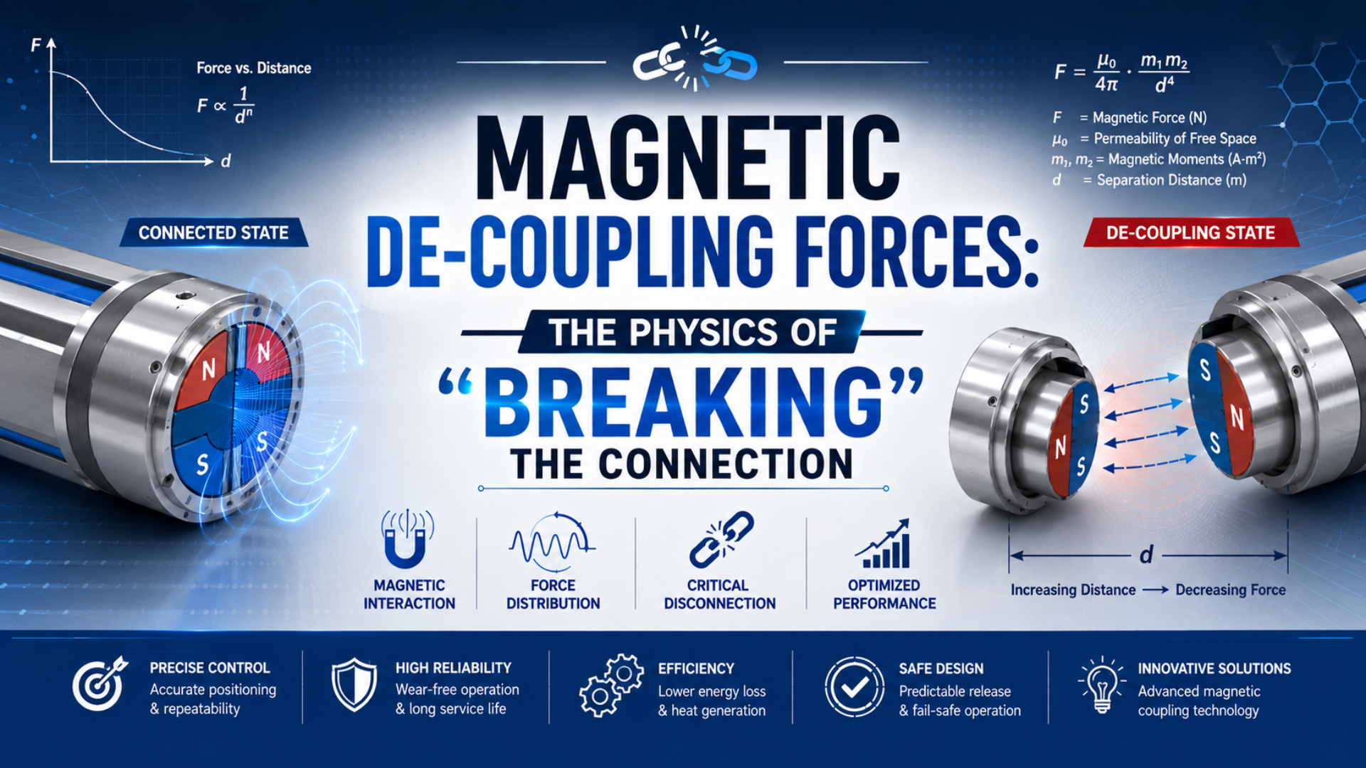
Magnetic de-coupling is the loss of synchronized movement between the internal piston and external carriage of a magnetically coupled rodless cylinder. The magnets haven’t necessarily failed. More often, a short force spike, rising guide resistance, a hard stop, or an obstructed carriage has exceeded the model’s axial coupling limit.
That distinction changes the investigation. Replacing the cylinder without finding the transient load can leave the same fault in the machine. This guide focuses on reconstructing the event, separating magnetic force from pneumatic thrust, and restoring the axis safely. For initial product sizing, use the separate magnetic coupling break-away force guide.
In our experience reviewing rodless-cylinder applications, repeated separation is rarely diagnosed by the catalog holding-force value alone. Preserving the stopped positions of the piston and carriage usually shortens the investigation because it distinguishes a coupling event from a general loss of motion.
Key Takeaways
- SMC publishes model-specific holding forces from 19.6 to 2,256 N; there is no universal de-coupling value.
- Reconstruct axial demand from process force, guide resistance, inertia, and gravity.
- Check side load as a guide-force or moment problem.
- Isolate energy and follow the manufacturer’s recoupling procedure.
What Actually Breaks During Magnetic De-coupling?
SMC lists nine CY3B magnet holding-force values from 19.6 to 2,256 N, while Parker lists five P1Z magnetic pull-off forces from 157 to 942 N. Those ranges show that de-coupling is a model-specific loss of synchronized force transmission, not a universal magnetic threshold (SMC CY3B; Parker P1Z).
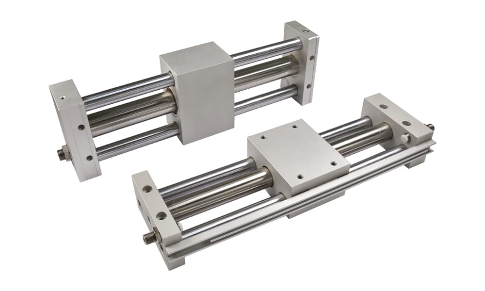
A magnetically coupled rodless cylinder has a pressure-tight tube, an internal piston, and an external carriage. Permanent-magnet assemblies transmit axial force through the tube wall. When the coupling is intact, piston and carriage position remain synchronized.
The connection is force-limited. If the piston advances but the carriage is blocked, the relative magnetic displacement increases until the assemblies slip into another position. The carriage may stop, jump, or lag behind. Depending on the circuit and available stroke, the internal piston may continue toward the end cap.
Pneumatic thrust is separate from magnetic holding force. Pressure acting on piston area generates piston force; the coupling transmits only the available axial force to the carriage. Higher pressure doesn’t strengthen the magnets. During a jam, it can increase the force pushing the internal piston against a stationary carriage.
Festo makes the same separation visible in its DGO data. The catalog lists both theoretical force at 90 psi and magnetic breakaway force for each bore, then provides separate permissible axial-force, lateral-force, moving-mass, and speed information (Festo DGO).
Which Forces Should Be Reconstructed After an Event?
Parker publishes a 703 N magnetic pull-off force for its 32 mm P1Z, but the same catalog family also separates pneumatic force, permissible loads, moments, speed, and cushioning. A useful event reconstruction therefore calculates axial demand first and checks guide loads, moments, and stopping energy independently (Parker pneumatic catalog).
For a first axial-force estimate, use:
Here, is axial demand in newtons, is the external process force along the travel axis, is measured or estimated guide resistance, is total moving mass, is axial acceleration, is gravitational acceleration, and is the travel angle measured from horizontal.
Use signs that match the direction being checked. Gravity can assist one stroke and oppose the other. The process force can change at clamp engagement, product contact, cutting, sealing, or connector insertion. Guide resistance may also differ by position.
What’s missing from the equation? Side load isn’t converted with a universal multiplier. A transverse force can overload a guide, tilt the carriage, increase friction, or create a moment. SMC instead uses the axial resisting force and the distance between the cylinder centerline and force-application point to select from model-specific allowable-driving-force curves (SMC CY3B/CY3R selection data).
| Demand or constraint | How to quantify it | Evidence to collect |
|---|---|---|
| Process force | Force along the travel axis | Process specification or load-cell trace |
| Guide resistance | Pull force at several carriage positions | Controlled force-gauge test with air isolated |
| Inertia | Total moving mass multiplied by acceleration | Motion-command and measured velocity data |
| Gravity | Axial component of moving weight | Mounting angle and verified moving mass |
| Side load and moments | Manufacturer guide-force and moment method | Load center, offsets, guide geometry, alignment |
| Stopping energy | Moving mass and velocity at the stop | Velocity trace immediately before deceleration |
The distinction between force and constraint is practical. Axial terms build the coupling demand. Side loads and moments define whether the selected carriage or external guide can move without binding. Combining all six quantities into one invented force total hides the component that maintenance needs to correct.
In application reviews, we treat the catalog holding-force value as a product limit to investigate, not as approval for the complete machine. The installed guide, load offset, motion profile, stop, and control response still need their own evidence.
In our experience, guide resistance that changes with stroke position deserves attention before the cylinder is upsized. A larger coupling can temporarily overpower the resistance while leaving rail alignment, carriage loading, or cable drag unresolved.
How Can the Motion Profile Reveal the Force Spike?
Festo’s DGO catalog plots permissible piston speed against moving mass and instructs users to add suitable external cushioning when operating conditions fall outside the permitted range. That warning links de-coupling to the actual velocity profile and stopping method, not merely to average stroke speed (Festo DGO).
A PLC command may specify stroke time but not show the resulting acceleration. Record position at a high enough sample rate to calculate velocity, then calculate acceleration from the slope of that velocity trace. Check normal travel, product engagement, intermediate stops, and both end positions.
For a symmetrical trapezoidal profile with equal acceleration and deceleration times:
In this relationship, is total stroke in metres, is acceleration time in seconds, is constant-speed time, and is acceleration in metres per second squared. The relationship assumes zero initial and final velocity and equal acceleration and deceleration magnitudes.
Consider a hypothetical 1.5 m move with 0.5 s acceleration, 1.0 s at constant speed, and 0.5 s deceleration. The calculated acceleration is 2.0 m/s². For 24 kg of total moving mass, the inertial term is 48 N. That is only one term in the axial budget.
The average speed of this move doesn’t expose a short impact. If a stopper arrests the carriage while the piston remains pressurized, force may rise after carriage velocity reaches zero. If the stopper is contacted at speed, the relevant kinetic energy is:
Here, is kinetic energy in joules, is moving mass in kilograms, and is velocity immediately before the stop in metres per second. Compare the result with the exact cylinder cushion, shock absorber, or stopper rating. The cushion energy calculator can check this term, but it doesn’t approve the magnetic coupling or guide.
SMC lists model-specific intermediate-stop energy limits from 0.007 to 5.07 J for the CY3B family and pairs them with operating-pressure limits. A static holding-force comparison alone can’t validate a fast intermediate stop (SMC CY3B).
Evidence That Confirms a De-coupling Event
Parker’s P1Z troubleshooting table identifies an interrupted magnetic coupling when the carriage doesn’t reach the end position, and its instructions provide a separate piston-to-carriage reconnection procedure. Confirmation therefore depends on position relationship and controlled inspection, not on motor current, valve sound, or one end sensor alone (Parker P1Z instructions).
Start with the commanded direction and final carriage position. Then determine where the internal piston stopped. A cylinder-mounted position switch may detect the piston magnet rather than the external carriage, so a sensor can indicate stroke completion while the load remains behind. The exact behavior depends on the sensor arrangement.
Add an independent carriage-position reference when separation must be detected automatically. It might be a second proximity switch, encoder, linear sensor, or machine-side confirmation switch. The cylinder position-sensing guide explains the main technologies, but the key requirement here is comparing piston and carriage position.
Use the evidence pattern, not a single symptom:
| Observation | Likely interpretation | Next check |
|---|---|---|
| Piston sensor changes, carriage sensor doesn’t | Position synchronization may be lost | Isolate energy and locate both components |
| Both positions stop together and pressure stays low | Supply, valve, or flow restriction is more likely | Measure both port pressures during the event |
| Carriage slows at the same physical location | Guide misalignment, contamination, or obstruction | Measure pull resistance across the full stroke |
| Event appears only at a hard or intermediate stop | Stop force or trapped pressure may be too high | Record velocity and both port pressures |
| Event appears after payload or tooling change | Axial demand or guide moment has changed | Rebuild the mass, force, and offset inputs |
| Carriage moves but the piston doesn’t | Mechanical obstruction or an incorrect position assumption | Verify piston location and circuit state |
Pressure deserves its own trace. A plant gauge several metres upstream can’t show cylinder-port pressure during a 100 ms event. Long tubing, small fittings, restricted exhaust, and silencers can all change the local pressure history. Compare the data with the pressure-fluctuation diagnostic guide.
A Controlled Field Diagnostic Sequence
Parker lists five P1Z pull-off values between 157 and 942 N and warns that the cylinder contains strong magnets, crushing hazards, and possible residual pressure after venting. A field test must therefore preserve position evidence while controlling stored energy and avoiding an uncontrolled reconnection (Parker P1Z instructions).
First, save the PLC alarm history, command state, sensor transitions, and any available pressure or position trends. Don’t manually move the carriage yet. Its stopped position relative to the commanded endpoint can identify where synchronization was lost.
Second, apply the machine’s energy-isolation procedure and secure any load that gravity could move. Confirm pressure at the relevant points rather than assuming that an exhausted valve has removed every trapped volume. ISO 14118 covers prevention of unexpected start-up from electrical, pneumatic, stored, and external energy sources (ISO 14118:2017).
Third, inspect the full mechanical path:
- Look for product contact, stopper contact, cable drag, hose pull, or tooling interference.
- Check the carriage and external guide for contamination, damage, looseness, and abnormal resistance.
- Verify guide-rail parallelism and load-center offsets against the installed drawing.
- Inspect the cylinder tube for dents, magnetic debris, or surface damage.
- Compare payload, tooling, speed, pressure, and stop settings with the approved machine state.
Fourth, measure breakaway and running resistance only with a defined fixture and safe machine state. Pulling an assembled carriage can also move the internal piston, seals, and bearings. A handheld force-gauge value is meaningless unless the restrained component, pressure state, direction, speed, temperature, and test points are repeatable.
A rising resistance trace before the event often points to alignment, contamination, or cable-management problems. A short spike with otherwise stable resistance points more strongly to acceleration, process contact, or stopping. This pattern is more useful than labelling every separation as “weak magnets.”
How Should the Piston and Carriage Be Re-coupled?
Parker dedicates a separate procedure to connecting a separated P1Z piston and carriage, including warnings about crushing, strong magnetic fields, and residual pressure. Recoupling should therefore follow the exact manufacturer instructions after the initiating obstruction or overload has been corrected, not serve as the first troubleshooting action (Parker P1Z instructions).
Before attempting recovery:
- isolate the machine according to its approved safety procedure;
- support vertical or suspended loads independently;
- confirm the positions of both the internal piston and external carriage;
- inspect the tube and carriage for damage or magnetic debris;
- remove the obstruction and correct guide alignment;
- identify the approved end position, pressure limit, and reconnection sequence for the exact model.
From our work reviewing pneumatic axes, a recoupling that isn’t followed by a controlled low-risk test leaves the initiating fault unverified. The axis should prove synchronized movement before normal payload, pressure, and speed are restored.
Don’t assume every magnetic cylinder is reconnected by pushing the carriage by hand. Parker’s P1Z instructions specify a sequence that uses an end position and controlled compressed air, while warning against manually pushing the carriage onto the piston. Another manufacturer or series may prescribe a different method.
ISO 4414:2010 covers general rules and safety requirements for pneumatic systems, including installation, adjustment, maintenance, reliable operation, and significant pneumatic hazards. The ISO page states that the 2010 edition was confirmed in 2021 and remains current (ISO 4414:2010).
After recoupling, test at reduced risk under the manufacturer’s commissioning instructions. Confirm piston and carriage synchronization in both directions, then restore normal payload, speed, pressure, and stop conditions one variable at a time. Record the corrected baseline so a future change is visible.
Which Design Changes Prevent a Repeat Event?
SMC’s CY3B/CY3R selection method uses load mass, guide friction, pressure, speed, stroke, mounting direction, and load-application distance, while Festo provides speed-versus-moving-mass envelopes. Prevention is therefore a system design task, not a fixed percentage deducted from catalog holding force (SMC selection data; Festo DGO).
Use the correction that matches the evidence:
- High axial demand: reduce process force or acceleration, increase the approved actuator capacity, or revise the motion sequence.
- Guide resistance: clean, repair, realign, or replace the guide; correct cable and hose drag.
- Excess moment: move the load center closer, widen or upgrade the external guide, and verify mounting geometry.
- Hard stop: reduce entry speed or install a correctly sized cushion, shock absorber, or external stop. The external shock absorber sizing guide covers the separate energy check.
- Pressure-driven separation at a stop: review valve center condition, trapped volumes, regulators, and the permitted intermediate-stop circuit.
- Contamination: shield the travel path and remove ferrous debris without damaging the tube surface.
- Undetected separation: compare piston and carriage position in the control logic and define a safe fault response.
The rodless cylinder mounting guide and guide-rail parallelism analysis help when resistance varies with position. For technology selection, compare the different failure modes in the magnetic-versus-mechanical coupling guide.
Treat magnetic separation as a detectable overload mechanism, not as normal cycle control. If the machine depends on separation to limit force, the actual separation point varies with the selected product, installed resistance, temperature, alignment, and dynamic state. A purpose-designed force-limiting or safety function needs its own validated architecture.
Finish by updating the machine baseline: total moving mass, load offsets, measured guide resistance, pressure at both ports, velocity profile, cushion or stopper settings, and piston-to-carriage position relationship. Add those checks to the machine’s maintenance plan at intervals supported by the exact manufacturer and operating environment.
Magnetic De-coupling FAQs
SMC’s 19.6-2,256 N holding-force range, Parker’s 157-942 N pull-off range, and Festo’s model-specific breakaway values lead to the same answer: magnetic de-coupling cannot be diagnosed from bore size or payload alone. Force, resistance, offset, speed, stopping, pressure, and position evidence must be reviewed together (SMC; Parker; Festo).
Is magnetic holding force the same as pneumatic thrust?
No. Pneumatic thrust comes from pressure acting on piston area. Magnetic holding or pull-off force limits the axial force transferred from the internal piston to the external carriage. Parker publishes these as separate values for P1Z cylinders. Guide-force, moment, speed, and cushioning limits require additional checks.
Does higher pressure increase magnetic coupling force?
No. Raising pressure increases available piston thrust but doesn’t strengthen a permanent-magnet coupling. If the carriage is obstructed or held at an intermediate stop, additional piston thrust can increase the tendency to separate. Check the model-specific pressure and stop limits rather than relying on the cylinder’s general pressure range.
Can side load cause a magnetic rodless cylinder to de-couple?
Yes, but not through a universal side-load percentage. Side load can increase guide friction, tilt the carriage, alter clearance, or overload a bearing. Any resulting axial resistance can contribute to separation. Check guide forces and moments using the selected manufacturer’s method and measure resistance across the installed stroke.
Can a handheld force gauge verify the magnetic coupling?
Only in a controlled and repeatable fixture. Pulling the carriage may also move the piston, seals, and bearings, so the reading can include more than magnetic force. Define pressure state, restrained component, direction, pull speed, temperature, alignment, and test positions before comparing a result with manufacturer data.
What should be checked before re-coupling the piston and carriage?
Isolate machine energy, support gravity loads, verify residual pressure, locate both components, and remove the initiating obstruction. Inspect the tube, guide, carriage, and mounting before following the exact model’s reconnection procedure. Confirm synchronized motion at reduced risk before returning the axis to normal production conditions.
Sources and technical references
- SMC CY3B magnetically coupled rodless cylinder catalog, holding force, operating range, intermediate-stop energy, and pressure limits. Retrieved 2026-07-26.
- SMC CY3B/CY3R model-selection catalog, driving resistance, load offset, allowable-driving-force curves, and mounting guidance. Retrieved 2026-07-26.
- Parker P1Z operating instructions, pull-off force, hazards, troubleshooting, maintenance, and piston-to-carriage reconnection. Retrieved 2026-07-26.
- Parker pneumatic catalog, P1Z force, load, moment, speed, and cushioning data. Retrieved 2026-07-26.
- Festo DGO technical data, breakaway force, permissible load, moving-mass, speed, and external-cushioning guidance. Retrieved 2026-07-26.
- ISO 4414:2010, general rules and safety requirements for pneumatic systems and components. Confirmed 2021.
- ISO 14118:2017, prevention of unexpected machine start-up from pneumatic and other energy sources. Retrieved 2026-07-26.