

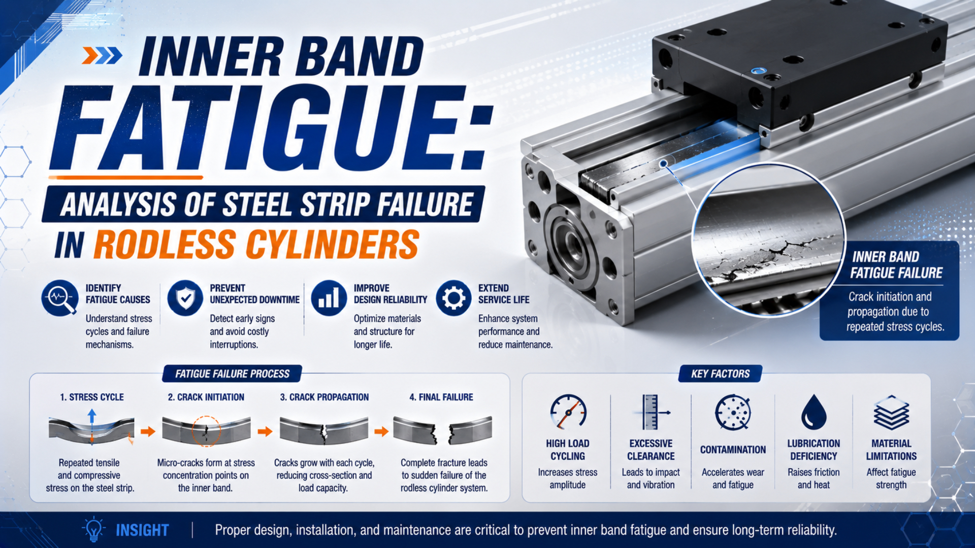
Inner band fatigue is a possible failure mechanism in a mechanically jointed rodless cylinder, but it is not a diagnosis that can be made from a hiss, jerky motion, or a scratched outer band alone. A defensible diagnosis needs the failed component, damage pattern, location, loading history, and cylinder condition to agree.
The practical question is therefore not simply, “Did the band fail?” It is, “What evidence shows that repeated flexing initiated and propagated the damage?” That distinction separates fatigue from a kink introduced during service, debris scoring, corrosion, guide misalignment, or leakage elsewhere in the pneumatic circuit.
Key Takeaways
- A hiss near the carriage does not prove inner band fatigue.
- Parker rejects an inner band with a nick, kink, or damaged edge.
- Bending strain is useful for screening, not for predicting universal service life.
- Repair decisions must include the cylinder bore, guide, clamps, and failure history.
Rodless cylinder inner band fatigue is progressive damage caused by repeated flexing of the pressure-sealing strip around the moving piston-yoke region. It applies only where the actuator actually uses that band architecture. SMC, for example, describes its MY1 component as a flexible seal belt, while Parker identifies stainless steel inner and outer bands on the OSP-P family.
Does a Hiss Prove Inner Band Fatigue?
No. Parker’s RC maintenance instructions cover 5 bore sizes from 25 to 63 mm, yet their inspection sequence checks the inner band, cylinder-body inside diameter, carriage supports, seals, and assembly condition rather than assigning every leak to the band (Parker RC Maintenance Instructions, retrieved 2026-07-26).
A hiss that follows the carriage makes the slot-sealing system a reasonable suspect. It still does not distinguish an edge defect from poor seating, a damaged piston seal, contamination under the band, or an assembly error. A hiss fixed at an end cap or fitting points elsewhere. Jerky motion is equally nonspecific because guide friction, flow restriction, and stick-slip behavior can produce similar motion.
Start by identifying the actuator architecture. A mechanically jointed rodless cylinder has a longitudinal slot through which the piston yoke connects to the external carriage. A magnetically coupled cylinder transfers force through a closed tube wall and does not use the same long pressure-sealing strip. SMC’s MY1 web catalog also shows 5 guide types and bore availability from 10 to 100 mm, evidence that even one mechanically jointed family contains several hardware arrangements (SMC MY1 Web Catalog, retrieved 2026-07-26).
Use a controlled location test before disassembly:
- Isolate the machine according to the site’s energy-control procedure.
- Check fittings, ports, end caps, cushion adjusters, tubing, and the valve first.
- Move the carriage slowly and mark where the sound begins, peaks, and stops.
- Repeat the test from both directions.
- Compare the leak location with visible band, slot, wiper, and guide damage.
- If the circuit can be isolated safely, quantify decay instead of relying on sound alone.
The pressure-decay leak rate calculator can help quantify an isolated volume, but it cannot identify which internal part is leaking. For the broader component distinction, see the guide to rodless cylinder sealing band technology.
From our analysis of repeat-failure reports, a leak at one physical stroke coordinate is more useful than a general hiss. The fixed coordinate directs attention to local band, slot, barrel, or frame damage. A symptom that travels with the carriage directs attention toward the moving yoke, wipers, guide alignment, piston seals, or debris carried by the carriage.
How Does Repeated Bending Load a Steel Inner Band?
Repeated flexure can create alternating surface strain, but one bend radius does not establish service life. MIT’s beam relation gives longitudinal strain as ; applying it at the outer surface of a strip gives a first screening estimate for the bend (MIT OpenCourseWare, 2003, retrieved 2026-07-26).
For a thin strip with its neutral axis near the mid-thickness, the outer-fiber bending strain is approximately:
Here, is nominal outer-fiber bending strain, is strip thickness, and is the neutral-axis bend radius imposed by the carriage geometry. Both and must use the same length unit. This equation is an elastic, geometry-only screen. It does not include notches, residual stress, surface finish, corrosion, contact pressure, plastic strain, or material fatigue data.
What does the relationship tell you? A thicker strip or tighter radius increases nominal strain. It does not tell you how many cycles a proprietary band will survive. That prediction needs the actual material condition, edge quality, local geometry, stress ratio, environment, manufacturing history, and statistically valid test data.
For a point inside the active stroke, one complete out-and-back cycle normally brings the moving yoke past that point twice. A useful exposure counter is therefore , provided the commanded stroke crosses that location in both directions. End zones, partial strokes, dwell patterns, and multi-carriage designs need their own count.
In our experience, this local count explains why machine cycle totals can mislead. A defect outside the commanded stroke may see few passages, while a short high-frequency stroke repeatedly loads the same narrow region. Map the real motion window before comparing failures from two machines.
Damage Morphology Separates Fatigue from Other Failures
Parker names 3 direct inner-band rejection signs in its RC instructions: nicks, kinks, and damage to the sharp edge. The same document separately requires inspection of the cylinder-body inside diameter for scratches, grooves, and scoring, so those observations must not be collapsed into one generic “fatigue” label (Parker RC Maintenance Instructions, retrieved 2026-07-26).
True fatigue evidence is a progressive crack associated with repeated loading. An edge-origin crack near the recurring flex zone is stronger evidence than a random scratch, but the conclusion still depends on the fracture surface, crack direction, location, and operating history. A single sharp fold is more consistent with handling or assembly damage. Long polished scoring points toward sliding contact or entrained debris.
| Observed pattern | More consistent with | Evidence to collect next | Immediate disposition |
|---|---|---|---|
| Edge-origin crack in the repeated flex zone | Fatigue from cyclic bending, possibly amplified by an edge defect | Magnified crack origin, local radius, strip thickness, passage count | Replace band; investigate geometry and edge condition |
| Sharp kink or permanent crease | Installation, tool contact, forced routing, or impact | Clamp history, service photos, yoke path, nearby sharp edges | Replace band; do not straighten for reuse |
| Longitudinal polished line or groove | Debris, burr, misaligned contact, or slot damage | Matching mark on body, wiper, guide, or yoke | Correct contact source before fitting a band |
| Multiple pits with cracks initiating at pits | Corrosive exposure followed by cyclic loading | Fluid chemistry, cleaner, humidity, deposits, material identification | Replace affected parts and control exposure |
| Damage concentrated at a clamp or band end | Incorrect retention, offset, loose hardware, or excess force | Clamp alignment, torque procedure, end geometry | Repair retention system and replace damaged band |
| Outer dust-band dent with no pressure leak | External impact or contamination-control damage | Inspect inner band separately; run an isolation test | Service outer band based on its own criteria |
Do not infer inner-band condition from the outer dust band alone. The two parts have different jobs. The engineering guide to rodless cylinder dust bands explains why an external dent may compromise contamination protection without proving pressure-boundary failure.
What Operating Evidence Should You Collect?
Use a record that ties each defect to loading history and location. ISO 12107:2012 is a 36-page standard for planning fatigue tests and statistically analyzing metallic-material data; it seeks confidence with a practical number of specimens, not a universal life number from one failed strip (ISO 12107, 2012, retrieved 2026-07-26).
A production failure investigation is not the same as a controlled material test, but the evidence discipline transfers. One strip from one actuator cannot establish a general kilometer or cycle rating. It can, however, support a root-cause hypothesis when the fracture morphology, local motion count, geometry, and service conditions agree.
Collect these fields before the unit is cleaned or dismantled:
- Manufacturer, full model code, serial number, bore, stroke, carriage count, and guide type
- Commanded motion window, cycles per minute, dwell time, acceleration, speed, and end-stop behavior
- Load mass, offset, pitch/yaw/roll moments, external guide arrangement, and mounting flatness
- Working pressure at the actuator, exhaust restrictions, cushion setting, and recent circuit changes
- Ambient and compressed-air temperature, particles, condensate, cleaner, coolant, and corrosive exposure
- Exact defect coordinate measured from one end cap and whether the symptom follows the carriage
- Close photographs of both band faces, both edges, the crack origin, slot, body, clamps, wipers, and guide
- Service history, replacement-part identity, installation method, tightening sequence, and first symptom date
Parker’s OSP-P instructions specify an 8 bar maximum pressure, a -10 to 80 degrees C range, water- and dirt-free compressed air, and permanent grease lubrication for that series (Parker OSP-P Maintenance Instructions, retrieved 2026-07-26). These are product-specific limits, not universal rodless-cylinder rules. They also show why “dry air caused it” is too vague: the same manual says additional oil mist is not necessary and must be supplied continuously if used.
In our experience inspecting replacement parts, a photograph of the crack alone is rarely enough. The highest-value evidence usually includes a scale, the full band edge, the corresponding stroke coordinate, and the mating surface. Those four views can distinguish a repeating local contact from damage that moves with the carriage.
Related investigations may require separate checks for contamination particle origins, side loading, or scratched cylinder bores.
When Should You Replace Only the Band?
Replace only the band when the cylinder body, sealing interfaces, piston seals, guides, supports, clamps, and carriage path remain serviceable. Parker’s RC documentation lists band kits by inner or outer function, single or double carriage, bore, and stroke, proving that strip length alone is not a valid replacement specification (Parker RC Maintenance Instructions, retrieved 2026-07-26).
Parker instructs technicians to replace the inner band if any nick, kink, or edge damage is evident. It also says a badly damaged cylinder body should be replaced when its inside diameter has scratches, grooves, scoring, or other imperfections. That is a condition-based rule. It does not depend on an arbitrary 63 mm bore threshold or a generic comparison between repair labor and cylinder price.
Use this disposition matrix:
| Inspection result | Band-only repair? | Required action before return to service |
|---|---|---|
| Band rejected; body and mating path undamaged | Potentially yes | Fit the exact model-, bore-, stroke-, and carriage-specific band |
| Body has severe scoring or grooves | No | Replace or repair the body using manufacturer-approved parts |
| Guide play or misalignment changes band entry path | Not yet | Correct the guide/load problem before installing a new band |
| Clamp, retainer, or end geometry is damaged | Not yet | Restore retention and centering to the series specification |
| Piston seals, wipers, or bearing strips are worn | Usually a broader service package | Replace the affected parts and verify the complete sealing path |
| Cause remains unknown after repeat band failures | No blind repeat repair | Escalate to dimensional and fracture analysis |
Can a kink be pressed flat and reused? No general rework limit supports that decision. Straightening changes residual stress and does not remove sharp local deformation or unseen cracking. Where the manufacturer identifies a kink as rejection damage, replace the band.
Band adjustment is also model-specific. Parker’s RC instructions say to remove slack, not tension the inner band, and warn that excessive force may move or damage it. Follow the exact service manual, tightening values, orientation, and assembly tools for the installed series. A generic “make it tight” instruction can create the next failure.
A Repeatable Inner Band Failure-Analysis Workflow
Use a 6-stage workflow that keeps symptom confirmation ahead of teardown. Parker’s current OSP-P product page spans 8 bore sizes from 10 to 80 mm and strokes up to 6,000 mm, so a useful method must preserve series-specific dimensions rather than substitute one universal wear limit (Parker OSP-P Product Page, retrieved 2026-07-26).
1. Confirm the architecture and failed function
Identify whether the actuator is mechanically jointed and slotted. Then separate the inner pressure band, outer cover band, wipers, piston seals, ports, valve, and end seals. Record the part names from the manufacturer drawing, not from appearance alone.
2. Reproduce and locate the symptom
Mark the carriage position, motion direction, pressure state, temperature, and operating speed when the leak or drag occurs. Repeat at controlled speed. A fixed-coordinate symptom and a carriage-following symptom lead to different inspections.
3. Preserve the evidence
Photograph and label the actuator before cleaning. Protect the band edges and fracture surfaces. Do not grind, straighten, polish, or wipe away deposits that may identify the origin. If a fracture analysis is planned, agree on handling and packaging with the laboratory first.
4. Classify the morphology
Separate edge cracks, kinks, longitudinal scoring, pits, clamp-zone damage, and body scoring. Use magnification and adequate lighting. Look for a matching witness mark on the slot, body, yoke, wiper, clamp, or guide.
5. Test the mechanism against the history
Compare the proposed cause with the active stroke, local passage count, bend path, guide moments, contaminants, temperature, and service record. If the pattern does not match the history, keep the cause open. Fatigue should explain both the crack and where it occurred.
6. Correct the system and verify
Replace all rejected parts, correct the initiating condition, and assemble to the exact manufacturer procedure. Begin verification at controlled pressure and speed. Check smooth reseating, leakage over the full stroke, guide behavior, cushion performance, and repeatability before restoring normal production.
The investigation is complete only when the corrective action addresses the initiating condition. A fresh band installed over a scored body, contaminated slot, skewed guide, or damaged clamp is a replacement event, not a root-cause correction. For long-stroke duty, the companion guide to rodless-cylinder durability in continuous operation covers the wider axis review.
Rodless Cylinder Inner Band Fatigue FAQs: What Should Maintenance Teams Ask?
SMC’s MY1 family includes 5 standardized guide types and bore sizes from 10 to 100 mm, while Parker’s RC service instructions cover a different 25 to 63 mm range (SMC MY1 Web Catalog, retrieved 2026-07-26). These answers state transferable diagnostic rules and leave dimensions, tension, torque, and part selection to the exact manufacturer documentation.
Does a hiss near the carriage prove inner band fatigue?
No. A carriage-following hiss makes the slot-sealing system a suspect, but it can come from band seating, piston seals, contamination, or assembly damage. Check fittings, valve leakage, end seals, and the symptom’s physical coordinate first. Fatigue requires a progressive crack pattern that agrees with repeated flexing and service history.
What damage pattern most strongly supports fatigue?
An edge-origin crack in the recurring flex zone, with evidence of progressive propagation and no single overload event, supports fatigue more strongly than a kink or longitudinal score. Confirm the origin under magnification and compare it with bend radius, local passage count, surface condition, corrosion, and nearby contact marks before assigning root cause.
Can a kinked inner band be straightened and reused?
Do not assume so. Parker identifies a kink as inner-band damage that requires replacement in its RC instructions. Flattening the strip does not remove residual deformation, edge damage, or small cracks. Install the correct replacement only after checking the yoke path, clamps, tools, slot, and handling method that produced the kink.
How should inner band slack or tension be set?
Use the exact service procedure for the installed series. Parker’s RC instructions say the goal is to remove slack, not tension the band, and warn that excessive force can displace or damage it. Band centering, orientation, clamp hardware, torque, and assembly tools vary, so a universal tension value is unsafe.
When should the cylinder body be replaced instead of only the band?
Replace or repair the body when its internal sealing surface is badly scratched, grooved, scored, or otherwise outside the manufacturer’s service limit. A new band cannot seal reliably against a damaged path. Also correct guide, clamp, piston, wiper, or alignment defects before deciding that a band-only repair is sufficient.
Sources and technical references
- Parker RC Series Rodless Cylinder Maintenance Instructions, retrieved 2026-07-26. Used for inspection rejection criteria, body damage, band ordering, safe handling, assembly centering, and slack guidance.
- Parker Modular Pneumatic Linear Drive System OSP-P Maintenance Instructions, retrieved 2026-07-26. Used for the stainless steel band architecture, pressure, temperature, compressed-air, and lubrication limits.
- Parker OSP-P Product Page, retrieved 2026-07-26. Used for current bore range, maximum standard stroke, repairability, and product-family boundaries.
- SMC MY1 Mechanically Jointed Rodless Cylinder Web Catalog, retrieved 2026-07-26. Used for guide-type, bore-range, flexible seal-belt, and dust-band design differences.
- ISO 12107:2012, Metallic Materials, Fatigue Testing, Statistical Planning and Analysis of Data, retrieved 2026-07-26. Used to define the evidence requirements for fatigue data and statistical life claims.
- MIT OpenCourseWare, Engineering Beam Theory, 2003, retrieved 2026-07-26. Used for the strain-curvature relation behind the thin-strip screening equation.