

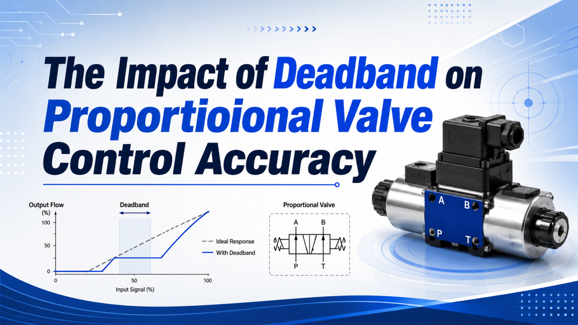
Proportional valve deadband is an input interval that produces no observable change in the chosen output after the command reverses direction. That output might be spool position, airflow, pressure, cylinder velocity, or axis position. Unless both variables are named, a deadband percentage says little about control accuracy.
Emerson defines deadband as the input range traversed after reversal before an observable output change begins, normally expressed as a percentage of input span. Its handbook also requires the input and output variables to be identified and quantitative tests to be performed under load (Emerson Control Valve Handbook, 6th ed., 2023).
Key Takeaways
- Deadband, hysteresis, sensitivity, resolution, and dead time describe different behaviors.
- Festo lists 0.4% maximum hysteresis for one MPYE family, not universal axis accuracy.
- Measure command and the controlled output in both directions under real load.
- Apply compensation only after mechanical, pneumatic, signal, and feedback faults are excluded (Festo MPYE, 2025).
This guide deals with the narrow diagnostic question: how an inactive command interval enters a pneumatic control loop and how to measure it. For valve-family selection, use the proportional-valve motion-control guide. For complete sensor, valve, controller, and cylinder architecture, see the cylinder position-control guide.
What Is Proportional Valve Deadband?
Emerson’s 2023 handbook states that many regulatory control actions are 1% of input span or smaller, so an inactive interval can swallow a normal correction. It also treats friction, backlash, shaft wind-up, and relay or spool dead zones as distinct contributors to assembly deadband (Emerson, 2023).
Start by defining the measurement boundary. If the input is a 0-10 V command and the output is measured mass flow, the result is command-to-flow deadband. If the output is spool feedback, it is command-to-spool deadband. If the output is cylinder position, the measured gap belongs to the installed axis, not the valve alone.
The direction reversal matters. Suppose the command has been rising and the output is stable. When the command begins falling, friction, mechanical overlap, magnetic effects, controller thresholds, and pressure forces can allow the input to move without a detectable output response. The span between reversal and response is the measured deadband for that test.
This definition is different from a central dead zone, the inactive interval around a neutral command. A 5/3 proportional directional valve can exhibit both reversal deadband and a neutral flow dead zone. A normally closed 2/2 proportional valve can instead have a minimum opening current. Record the behavior actually measured rather than forcing every curve into one label.
Deadband is therefore an input-output contract, not a material property of the spool. Changing the observed output from spool position to chamber pressure can change the reported result because compressibility, tube volume, leakage, sensor resolution, and load now sit inside the measurement boundary.
Deadband, Hysteresis, Resolution, and Dead Time Are Different
SMC’s current ITV1100/2100/3100 catalog lists sensitivity within ±0.2% full scale, linearity within ±1% full scale, and hysteresis within 0.5% full scale as three separate specifications. None of those numbers is labeled cylinder position accuracy (SMC ITV, accessed 2026).
| Term | Practical meaning | What it does not establish |
|---|---|---|
| Deadband | Input change after reversal before the selected output responds | Absolute position error by itself |
| Neutral dead zone | Command interval around neutral with no intended positive or negative output | Reversal behavior across the full operating range |
| Hysteresis | Difference between rising and falling output at the same input | Sensor resolution or dynamic delay |
| Sensitivity or threshold | Smallest stated input or pressure change that initiates a specified response | Linearity across full scale |
| Resolution | Smallest output increment that can be distinguished | Repeatability under changing load |
| Dead time | Time from an input change to the first detected response | Size of a static input interval |
| Linearity | Deviation from a defined straight reference characteristic | Dynamic tracking accuracy |
The distinction changes troubleshooting. If a valve responds at once but follows different rising and falling curves, investigate hysteresis. If it produces discrete steps, inspect signal and sensor resolution. If the response begins late in time but at the expected command threshold, examine dead time, current dynamics, tubing, and pneumatic volume.
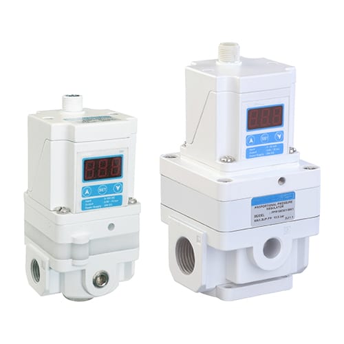
An electro-pneumatic pressure regulator controls outlet pressure, while a proportional directional valve meters both direction and flow. Their accuracy specifications cannot be interchanged.
If the controlled variable is unclear, compare proportional flow and proportional pressure control valves before interpreting any deadband or hysteresis figure.
Festo illustrates the device boundary clearly. Its VPPM pressure-regulator data lists 1% full-scale linearity, 0.5% full-scale hysteresis, 0.5% full-scale reproducibility, and 1.25% full-scale total accuracy as separate values (Festo VPPM, accessed 2026).
For calibration curves, linearity reference methods, and formal hysteresis calculations, use the dedicated hysteresis and linearity specification guide. Here, those terms are separated only to keep the deadband measurement boundary unambiguous.
What Creates a Dead Zone Near Valve Neutral?
Festo’s 2025 MPYE data specifies a position-controlled spool, a 5/3 closed-center function, and 0.4% maximum hysteresis relative to maximum spool travel. This architecture shows why spool feedback can reduce one internal error source without proving zero dead zone in the installed airflow or cylinder response (Festo MPYE, 2025).
Several mechanisms can create or enlarge an inactive interval:
- Intentional spool overlap: a closed-center valve may require spool travel before a metering edge opens. This limits leakage at neutral but creates a flow threshold.
- Static friction: seals, guides, contamination, and side forces resist the first movement. Once motion starts, running friction can be lower.
- Magnetic and current-control effects: coil force depends on current and armature position. Driver thresholds, current limits, or incorrect PWM settings can distort the command-to-force relationship.
- Pressure-force imbalance: supply pressure, exhaust pressure, and port geometry change the force required to move an internal element.
- Mechanical wear or looseness: wear can raise friction, while backlash can add a reversal gap between connected parts.
- Signal-chain thresholds: PLC scaling, output-card resolution, analogue filtering, zero clamps, and internal controller settings can create a dead zone outside the valve mechanics.
Coil inductance belongs primarily to dynamic response, not static deadband. It limits how quickly current changes. Likewise, a low-resolution analogue output can imitate deadband because several controller increments are required before the physical signal changes enough to be detected. Separating these effects prevents replacing a mechanically healthy valve for an electrical scaling problem.
Air quality also matters. Particles or degraded lubrication can increase friction and make the threshold drift between tests. The pneumatic valve contamination guide covers filtration and inspection without treating every sticky response as an electronic tuning fault.
Why Doesn’t Valve Deadband Equal Position Error?
Festo describes a servopneumatic positioning system as a cylinder with displacement encoder, proportional directional valve, and position controller. Its MPYE family spans 100 to 2,000 L/min nominal flow, so the installed axis also includes valve sizing, air conductance, sensor quality, controller behavior, load, and cylinder mechanics (Festo, 2025).
A valve specification is measured between defined valve variables. Axis position error is measured at the load. Between those boundaries are tube volume, chamber pressure, seal friction, guide friction, external forces, cushion behavior, compliance, sensor mounting, sample time, control law, and safety limits.
This is why multiplying a 1% valve figure by a 500 mm stroke does not prove a 5 mm positioning error. The valve percentage may refer to spool travel, pressure full scale, input span, or hysteresis. The axis might close the residual error with feedback, or it might oscillate because the controller repeatedly crosses an inactive region.
Three tests answer different questions:
- Command-to-spool test: isolates much of the valve electronics and mechanics when spool feedback is available.
- Command-to-flow or pressure test: includes metering edges, pressure conditions, and pneumatic load.
- Command-to-axis test: includes the entire machine and is the acceptance boundary for position accuracy.
Air compressibility further separates valve response from load response. A flow change must alter chamber mass and pressure before net force changes. That behavior is covered in how air compressibility affects cylinder control.
How Should Deadband Be Measured on a Real Machine?
Emerson’s flowing-condition comparison used command steps of 0.5%, 1%, 2%, 5%, and 10% to distinguish three valve assemblies. The handbook warns that stem movement alone can be misleading when the controlled flow does not change, so the selected process output must be recorded with the input (Emerson, 2023).
Choose one input and one observable output . For a neutral flow test, let be the negative-side threshold and the positive-side threshold at which $|y|$ first exceeds a documented detection criterion. The normalized inactive span is:
is the measured dead-zone width as a percentage of the tested input span. It is not automatically the manufacturer’s deadband specification. State the command units, output units, threshold rule, direction, supply pressure, downstream condition, temperature, load, and sampling method with the result.
Use a controlled procedure:
- Warm the electronics and valve to a repeatable operating state.
- Stabilize supply pressure and record pressure at the valve, not only at the compressor room.
- Disable adaptations that would change thresholds during the test, but keep required safety limits active.
- Move to a defined starting point and hold until pressure, flow, or position settles.
- Ramp or step the command in one direction with a rate appropriate to the device bandwidth.
- Record the command, coil current when available, spool feedback, pressure or flow, and final controlled variable on one time base.
- Repeat in the opposite direction and through multiple cycles.
- Reproduce the test at relevant load, pressure, temperature, and mounting conditions.
Don’t select an arbitrary 0.1% per second ramp or a fixed instrument accuracy for every valve. A rate that is slow for one pressure regulator can interact with leakage or controller integration in another system. The test rate and detection threshold belong in the report.
In our experience, plotting command, actual coil current, chamber pressure, and position together usually shortens the diagnosis. A flat command-to-current segment points upstream of the valve. Current without flow points toward valve mechanics or pressure conditions. Flow without expected motion redirects attention to the actuator, load, friction, or feedback.
The Input-Output Plot Makes the Fault Visible
Festo publishes both 0-10 V and 4-20 mA setpoint variants for the MPYE and specifies 0.4% maximum hysteresis relative to maximum spool stroke. A bidirectional plot should therefore preserve the native command scale and keep hysteresis separate from the central inactive span (Festo MPYE, 2025).
The vertical gap between rising and falling curves at the same input is not the same measurement as the central inactive span. Keep detection noise, saturation, and zero clamps out of either comparison or report them separately. Use the hysteresis and linearity guide when that directional curve error, rather than deadband, is the acceptance target.
When Can Deadband Cause Hunting or Limit Cycling?
Emerson notes that control corrections are commonly 1% of span or smaller and defines hunting as a sustained undesirable oscillation near the stability limit. Deadband can participate when the controller accumulates error until its command crosses the inactive region, but controller tuning and process dynamics determine whether oscillation actually persists (Emerson, 2023).
One common sequence is easy to recognize:
- Position error exists, but the controller correction remains inside the dead zone.
- Integral action continues to accumulate because the measured output has not responded.
- The command finally crosses the response threshold and airflow changes abruptly.
- The axis moves past the target or unloads stored pneumatic energy.
- The error changes sign, but the reverse correction must cross the opposite threshold.
- The cycle repeats if damping, friction, delay, and controller gain sustain it.
Deadband alone does not prove instability. A stable loop can tolerate a measured inactive region and settle inside an allowed position window. Conversely, a valve with a small catalog hysteresis value can still hunt when the loop has excessive integral gain, low damping, long delay, noisy feedback, an oversized valve, or asymmetric cylinder friction.
Inspect the trace before changing PID values. A sawtooth controller output that ramps across two repeatable thresholds suggests dead-zone interaction. Rapid noisy current with little spool movement suggests friction or driver behavior. Smooth spool movement with pressure oscillation shifts attention to flow capacity, air volume, load, or sensor placement.
How Should You Compensate for Proportional Valve Deadband?
A 2021 electro-pneumatic actuator study compared pole-placement control without compensation, conventional inverse dead-zone compensation, and a smoothed feed-forward method. In that specific test, the proposed method reduced baseline steady-state error by 90% and shortened settling and rise times by 30% and 40% (Sunar et al., 2021).
Those results support characterization-based compensation, not a universal offset. Apply corrections in this order:
- Remove physical faults. Correct contamination, damaged seals, loose couplings, side load, unstable supply pressure, blocked exhausts, and wiring errors.
- Verify the driver. Confirm command scaling, actual coil current, minimum and maximum current settings, PWM configuration, ramps, and zero cut-off against the exact valve and controller manuals.
- Map both directions. Identify positive and negative response thresholds over repeated cycles and relevant operating conditions.
- Add a directional feed-forward term. A simple starting model uses for positive commands and for negative commands, where and are measured directional offsets.
- Smooth the transition. A hard command jump at zero can create chatter. Blend or rate-limit the compensation within a documented transition region.
- Protect the integrator. Anti-windup and output limits prevent the controller from storing a large correction while the actuator is saturated or inactive.
- Retune and revalidate. Compensation changes effective loop gain near neutral. Repeat small-step, reversal, disturbance, and worst-load tests.
Do not copy a fixed dither recipe. Bürkert’s Type 8605 electronics offer adjustable PWM frequency and model-specific configuration because electromagnetic and fluidic response depend on the selected valve, coil, current range, and application (Bürkert 8605, accessed 2026).
For the broader gain, integral, derivative, and anti-windup workflow, use the separate proportional-valve PID tuning guide. Deadband characterization should be completed before aggressive tuning.
The safest compensation value is the smallest one that restores a repeatable response without creating a discontinuous output jump. If the identified thresholds drift significantly with pressure, temperature, or time, a static offset is hiding a changing fault. Use a scheduled map or repair the hardware rather than increasing the offset indefinitely.
What Should a Proportional Valve Specification Include?
Festo’s MPYE family combines 100-2,000 L/min nominal flow, five nominal sizes, 0-10 V or 4-20 mA setpoints, 0.4% maximum spool-travel hysteresis, and model-dependent 70-115 Hz limit frequency. These values describe different selection axes and must remain tied to the exact variant and test definition (Festo MPYE, 2025).
An RFQ or control specification should record:
- valve function: proportional pressure, 2/2 flow, or 5/3 directional control;
- manufacturer, complete model code, firmware, driver, and coil;
- command type and span, such as 0-10 V, 4-20 mA, or fieldbus;
- controlled output and feedback signal: spool position, pressure, flow, velocity, force, or position;
- deadband, neutral dead zone, hysteresis, sensitivity, repeatability, and linearity definitions;
- the reference input and output spans used for every percentage;
- supply and exhaust pressure, temperature, medium, flow direction, and downstream load;
- nominal flow or conductance and the pressure conditions used for that rating;
- dynamic data, including small-step response, limit frequency, filtering, and ramp settings;
- minimum current, maximum current, PWM frequency, zero cut-off, and current control method;
- cylinder bore, rod diameter, stroke, payload, orientation, guides, and friction-sensitive seals;
- encoder type, resolution, mounting, PLC scan time, controller sample time, and acceptance window;
- a loaded bidirectional acceptance test with raw traces and pass/fail thresholds.
Valve size still matters. Oversizing increases flow gain near small openings and can make each threshold crossing produce a larger pressure or velocity change. Use the flow-control valve sizing guide for capacity, but keep Cv or nominal flow separate from deadband.
For pressure-regulator applications, compare pressure-output specifications instead of borrowing directional-valve spool data. The proportional pressure regulator guide explains that device boundary.
A Commissioning Sequence That Separates Valve and Loop Faults
Bürkert specifies an adjustable 80 Hz to 6 kHz PWM range and a 0-10 second ramp function for current Type 8605 variants. Such a wide configuration range disproves the idea that one dither frequency or ramp rate suits every proportional solenoid valve (Bürkert Type 8605, 2026).
Commission from the signal outward:
- Signal layer: verify PLC engineering units, raw counts, polarity, zero, span, grounding, and actual voltage or current at the valve.
- Driver layer: log requested current and measured current. Confirm current control, PWM frequency, limits, filtering, and thermal behavior.
- Valve layer: measure spool feedback when available, then pressure or flow across increasing and decreasing commands.
- Pneumatic layer: record supply pressure at the valve, chamber pressure, exhaust condition, tube dimensions, and simultaneous air consumers.
- Mechanical layer: inspect guides, alignment, payload, breakaway friction, cushion entry, external stops, and side loading.
- Feedback layer: verify encoder direction, scaling, resolution, sample timing, mounting stiffness, and electrical noise.
- Control layer: begin with conservative gains, protect the integrator, and compare small steps with direction reversals.
- Acceptance layer: repeat at minimum supply pressure, maximum payload, thermal equilibrium, and sustained cycle rate.
Save the raw traces. A single displayed position number cannot show whether the valve failed to respond, the chamber pressure changed too slowly, the mechanism stuck, or the controller repeatedly crossed a neutral threshold. The pneumatic cylinder position-control article provides a broader commissioning record.
Proportional Valve Deadband FAQs: What Should Engineers Ask?
Current manufacturer data keeps the metrics separate: Festo lists 0.4% maximum hysteresis for the MPYE spool, while SMC lists 0.5% full-scale hysteresis and ±0.2% full-scale sensitivity for an ITV pressure-regulator family. These five answers explain what those numbers can and cannot establish in a machine (Festo; SMC, accessed 2026).
Is deadband the same as hysteresis?
No. Emerson defines deadband as an input interval traversed after direction reversal before the selected output changes. Hysteresis is the maximum difference between rising and falling output at the same input during a calibration cycle, excluding deadband under its definition. Report both variables and the test method (Emerson, 2023).
Does 0.5% valve hysteresis mean 0.5% cylinder position accuracy?
No. SMC’s 0.5% full-scale figure applies to hysteresis of a specified ITV pressure regulator, not cylinder travel. Axis error also depends on the controlled variable, valve function, airflow, pressure, load, friction, encoder, controller, tube volume, and acceptance method. Test the complete axis under load (SMC ITV, accessed 2026).
Can PID tuning remove proportional valve deadband?
PID can drive the command across an inactive interval, but it does not remove the physical nonlinearity. Excessive integral action can store error and contribute to overshoot or cycling. A 2021 experiment obtained better results by combining an identified dead-zone model with smoothed feed-forward compensation, then evaluating the closed loop (Sunar et al., 2021).
Should every proportional solenoid valve use dither?
No. Bürkert Type 8605 variants provide an adjustable 80 Hz to 6 kHz PWM range and valve-specific parameterization. The appropriate frequency, current range, and zero behavior depend on the exact coil, valve mechanics, fluid, pressure, driver, and control objective. Follow the matched valve-electronics documentation (Bürkert, accessed 2026).
How often should deadband be remeasured?
Use condition- and risk-based intervals rather than one calendar rule. Establish a loaded bidirectional baseline during commissioning, then repeat after valve, driver, seal, tubing, firmware, pressure, or mechanical changes and whenever reversal error or hunting trends shift. Emerson’s diagnostic approach compares current traces with an as-shipped baseline (Emerson, 2023).
Sources and Technical References
These 8 manufacturer, engineering, and peer-reviewed sources define deadband, separate model-specific static specifications, document 0.4% spool hysteresis and 70-115 Hz limit frequency, describe 80 Hz-6 kHz PWM electronics, and support measured dead-zone compensation. None provides a universal positioning-accuracy conversion (Festo; Emerson).
- Emerson, Control Valve Handbook, Sixth Edition, 2023. Retrieved 2026-07-22.
- Festo, Proportional Directional Control Valve MPYE, 2025/03. Retrieved 2026-07-22.
- Festo, Proportional-Pressure Regulator VPPM-6. Retrieved 2026-07-22.
- Festo, Servopneumatic Positioning Systems. Retrieved 2026-07-22.
- SMC, ITV1100/2100/3100 Electro-Pneumatic Regulator. Retrieved 2026-07-22.
- Bürkert, Type 8605 PWM Control Electronics. Retrieved 2026-07-22.
- Bürkert, Type 2873 Direct-Acting 2-Way Proportional Valve, 2026. Retrieved 2026-07-22.
- Sunar et al., Improved Pole-Placement Control with Feed-Forward Dead-Zone Compensation for Position Tracking of an Electro-Pneumatic Actuator System, 2021. Retrieved 2026-07-22.