

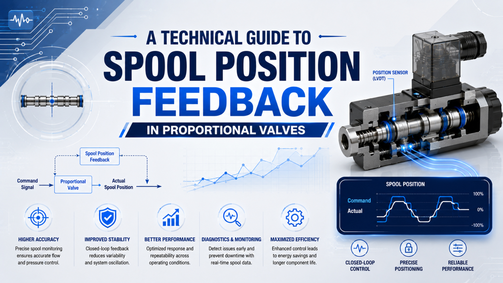
Spool position feedback lets a proportional valve measure its actual metering position and correct the difference between that position and the electrical command. It can reduce the effect of solenoid-force variation, friction, temperature change, and mechanical hysteresis on the spool itself.
That does not make valve position identical to flow, pressure, or actuator position. Flow still changes with the metering geometry and pressure ratio. Downstream pressure still depends on demand and volume. Cylinder motion still depends on compressibility, friction, load, tubing, and mechanics. The useful engineering question is therefore not simply whether a valve has feedback, but which variable is measured, which loop is closed, and which performance data apply to the complete machine.
Key Takeaways
- Internal spool feedback closes a position loop inside the valve; it does not close the machine’s pressure, flow, force, or motion loop by itself.
- An LVDT or magnetic sensor must be assessed as part of the valve assembly, including its mechanics, signal conditioning, electronics, and calibration.
- Product-level hysteresis, response, monitor-output, and fail-state data are more useful than generic claims about one sensor technology.
- Commissioning should trend command and actual-position signals together when the latter is exposed, then relate them to the real controlled variable.
- Calibration and retrofit procedures are model-specific. Do not adjust a sealed valve or add a sensor unless the manufacturer provides a supported method.
What Is Spool Position Feedback?
Spool position feedback is an internal measurement used to make the valve’s actual spool position follow its commanded position. The controller drives the proportional solenoid or pilot stage and reads a position sensor coupled to the spool. It then calculates the remaining position error and changes the drive until the error is reduced.
Festo describes its pneumatic MPYE proportional directional valve as having a “position-controlled spool.” An analogue command is converted into a corresponding opening cross-section at the valve ports. For pneumatic positioning, Festo separately adds an external position controller and displacement encoder. The complete positioning system therefore extends beyond the valve (Festo MPYE data sheet, retrieved 2026-07-22).
That distinction establishes two different control boundaries:
- Inner valve loop: command signal, valve electronics, solenoid or pilot stage, spool, and spool sensor.
- Outer process loop: the valve plus piping, actuator or process, process sensor, and machine controller.
Measure the variable you intend to control.
Some valves contain only the inner loop. Others are sold as pressure regulators with a different internal feedback variable. For example, Festo’s VEAB measures pressure at the working port and readjusts the valve when measured pressure differs from the setpoint (Festo VEAB data sheet, retrieved 2026-07-22). A product described as “closed loop” must therefore be checked for the actual measured variable instead of being assumed to contain spool feedback.
Internal Spool Loop Architecture
The internal loop continuously compares a spool-position setpoint with a measured spool position and changes actuator drive to reduce the difference. Its exact implementation is proprietary, but the functional sequence is consistent enough to review at the interface level.
- The valve receives a command through an analogue input or fieldbus object.
- Input electronics scale the command into an internal spool-position target.
- A current-controlled solenoid, force motor, or pilot stage moves the spool.
- A sensor reports actual spool displacement to the embedded controller.
- The controller changes drive until the measured position follows the target within the valve’s available authority.
The inner loop can compensate for several disturbances that act before or at the spool: coil resistance changes, magnetic-force variation, spring force, friction, and pilot-stage variation. It cannot remove a blocked silencer, undersized tube, unstable inlet pressure, cylinder seal friction, or changing payload. Those disturbances sit outside the measured boundary.
The valve’s electrical connector also deserves close attention. An integrated position loop does not guarantee that the actual spool signal is available to the PLC. The cited MPYE, for example, documents supply, ground, setpoint, and ground at its four-pin connection; it does not advertise an external spool-position monitor on that interface. Other valve families may provide an analogue monitor, fieldbus actual-value object, status bit, or no user-visible feedback at all.
Performance Boundaries of Spool Feedback
Spool feedback can improve command-to-spool repeatability, hysteresis, neutral control, and dynamic consistency, but only the manufacturer’s stated test data quantify the improvement. A generic “closed-loop valve accuracy” percentage cannot be transferred between sizes, spool cuts, electronics, pressure conditions, or manufacturers.
| Claim being evaluated | What spool feedback can support | What still requires separate evidence |
|---|---|---|
| Repeatable valve opening | Correction of measured spool-position error | Repeatability of actual flow at changing pressure ratios |
| Lower apparent hysteresis | Reduced command-to-position difference when approached from either direction | Machine hysteresis caused by seals, linkages, load, and structure |
| Stable neutral | Active correction around the calibrated spool datum | Leak-tight load holding or a safety-rated stop function |
| Faster response | Higher position-loop bandwidth within actuator and electronics limits | Cylinder settling time through the real tubes, ports, load, and exhaust path |
| Diagnostic visibility | Comparison of command and spool position when actual value is exposed | Identification of every downstream pneumatic or mechanical fault |
Flow is especially easy to overstate. A given spool position establishes an effective metering opening, but mass flow also depends on upstream and downstream absolute pressure, temperature, gas properties, port geometry, and whether the restriction is choked. A flow-controlled process therefore needs a flow sensor or a validated valve-flow model if changing pressure conditions matter.
Pressure regulation illustrates the same boundary. Festo’s closed-loop process-control paper describes proportional valves working with downstream sensors. It also places control performance at the level of the complete system, controller, and components (Festo, Proportional Valves for Closed-Loop Control, retrieved 2026-07-22). Spool feedback improves the actuator inside the valve; it does not replace the downstream measurement.
LVDT and Magnetic Spool-Sensor Implementations
LVDT and magnetic spool sensors are practical non-contact options, but the finished valve specification matters more than a technology label. The sensor must fit a short stroke and restricted package. It must also suit the vibration, temperature, electromagnetic environment, signal-conditioning architecture, and valve calibration process.
LVDT sensing
An LVDT is a position sensor that uses a movable magnetic core and transformer windings. The differential secondary signal changes with core position, while phase identifies the side of the electrical null. The sensor itself does not require sliding electrical contact between core and coils.
TE Connectivity explains that an LVDT has essentially continuous resolution in principle, but the usable system resolution is limited by the ability of the electronics to distinguish the output change from noise. Excitation, demodulation, wiring, signal-to-noise ratio, conversion, temperature effects, and mechanical coupling all remain part of the measurement chain (TE Connectivity, LVDT Terminology, retrieved 2026-07-22).
For valve assessment, ask for the assembled valve’s hysteresis, threshold, repeatability, drift, dynamic response, and monitor-output tolerance. A stand-alone sensor’s best-case resolution is not a valve flow-accuracy specification.
Hall and other magnetic sensing
A linear Hall-effect sensor is a device whose output changes with magnetic flux density. A magnet attached to or moving with the spool can therefore provide contactless position information. This approach can fit compact electronics, but accuracy depends on the magnet, air gap, alignment, temperature behavior, device sensitivity, mechanical tolerances, linearization, and calibration.
Texas Instruments’ design guidance shows that magnet dimensions, orientation, sensor placement, and array geometry influence a linear Hall position system. The correct comparison is therefore between validated valve assemblies, not “Hall versus LVDT” in isolation. The supporting design factors are documented in TI’s Linear Hall-Effect Sensor Array Design, revised 2024, and TI’s Contactless Linear Movement Sensing, retrieved 2026-07-22.
Magnetoresistive, inductive, optical, or magnetostrictive methods may appear in specialized position-sensing products. Do not assume they are available inside a pneumatic proportional valve unless the exact valve documentation identifies the sensor and its performance.
Comparing LVDT and Hall-Based Valves
Compare the complete valve under stated conditions rather than choosing from a generic sensor ranking. Either sensing method can be suitable when its travel, mechanics, electronics, environmental limits, and diagnostics match the application.
| Selection question | LVDT-based implementation | Hall-based implementation | Evidence to request |
|---|---|---|---|
| How is motion coupled? | Core moves relative to coil assembly | Magnet moves relative to sensor | Section drawing and allowable travel |
| What limits usable resolution? | Noise, conditioning, conversion, mechanics | Field gradient, noise, conversion, mechanics | Actual-value resolution and repeatability |
| What affects temperature behavior? | Winding, core, mechanics, conditioning electronics | Magnet, sensor sensitivity, mechanics, electronics | Drift or accuracy over rated temperature |
| What installation risks matter? | Core alignment, wiring, excitation, electromagnetic noise | Magnet alignment, air gap, nearby magnetic fields | Mounting tolerance and EMC test data |
| Can the PLC read actual position? | Only when the valve exposes a monitor or bus value | Only when the valve exposes a monitor or bus value | Pinout, object dictionary, scaling, update behavior |
| Can the user recalibrate it? | Model-dependent | Model-dependent | Manufacturer procedure and access level |
Do not award a technology an automatic win for accuracy, cost, life, or temperature range. Those conclusions require comparable part numbers, test conditions, and acceptance limits. If one quotation identifies only the sensor principle while another provides full valve curves and tolerances, the second quotation is technically more useful even before price is considered.
Reading Proportional-Valve Data Sheets
The most useful specifications connect the command, actual spool position, dynamic behavior, environment, and fault response. Port size and nominal flow alone do not reveal whether the valve can control a small opening or report a sensor fault.
Review these items for the exact order code:
- Command interface: voltage, current, PWM, or network; input range; impedance; polarity; neutral command; and out-of-range behavior.
- Actual-value interface: analogue monitor or bus object, scaling, offset, update rate, loading, tolerance, and whether it represents spool position or another variable.
- Static behavior: hysteresis, threshold, repeatability, linearity, overlap or underlap, neutral tolerance, and leakage, each with its reference basis.
- Dynamic behavior: step-response definition, frequency-response method, signal amplitude, supply condition, and valve size.
- Operating limits: supply pressure, medium, air-quality class, ambient and media temperature, duty cycle, vibration, shock, and ingress protection.
- Fault behavior: response to lost command, lost supply voltage, sensor failure, overheating, communications loss, and internal diagnostic faults.
- Calibration status: factory calibration, permitted zero or span adjustment, password or software requirements, and conditions that require requalification.
Festo’s MPYE data sheet is a useful example of model-specific reporting. It lists a maximum spool-position hysteresis of 0.4% and critical frequency values that vary with valve size; the same document defines the electrical input, air quality, temperature range, and overtemperature behavior. These are component specifications under the manufacturer’s conditions, not a promise of pressure, flow, or cylinder-position accuracy in every circuit.
When comparing quotations, copy the test basis into the comparison sheet. A percentage without a denominator is ambiguous: it may refer to full spool stroke, full-scale command, measured flow, or another range.
Commissioning Spool Feedback
Commissioning spool feedback begins with a low-risk check of signal direction and neutral. Then test command, actual spool position, and the process variable on one time base. If the valve does not expose actual spool position, use its status data and measure the downstream result without pretending that the internal trace is available.
Before applying pressure
- Confirm the complete part number, pinout, supply voltage, command type, pneumatic ports, permissible medium, and fail state.
- Check protective earth, cable shielding, analogue reference, isolation, and connector wiring against the manufacturer diagram.
- Verify PLC scaling without energizing motion. A 4 to 20 mA input must not be treated as a 0 to 20 mA input, and a bipolar command must not be mapped as unipolar.
- Establish the safe state independently of the normal spool controller. Internal feedback is not a substitute for risk assessment, isolation, exhaust, load restraint, or a certified safety function.
Low-energy functional test
Reduce available energy using the approved commissioning procedure. Confirm command polarity, port response, neutral behavior, and the effect of enable or disable. If an actual-position value is available, record its zero, full commanded range, saturation points, and behavior when approaching the same point from both directions.
Loaded trace test
Trend at least the command, actual spool position if exposed, and the controlled process variable. Add inlet pressure near the valve when supply dynamics could be limiting performance. Use a common timestamp and a sampling rate suitable for the specified response.
Run the defined operating cases rather than one unloaded stroke:
- minimum, normal, and maximum expected command;
- both approach directions around critical setpoints;
- normal and worst-case load or demand;
- cold start and thermally stable operation when temperature matters;
- supply-pressure limits during actual flow;
- disable, power-loss, sensor-fault, and communications-fault tests allowed by the manufacturer.
Approve the result against stated metrics such as tracking error, overshoot, settling time, steady-state deviation, repeatability, and safe-state response. Avoid replacing those measurements with the adjective “precise.”
Trace-Based Fault Diagnosis
The relationship between command, actual spool position, and the downstream variable helps separate an internal valve problem from a pneumatic or mechanical problem. One signal alone rarely identifies the cause.
Trace the boundary before tuning the loop.
| Observed trace | Likely fault region | Checks before changing control parameters |
|---|---|---|
| Command changes; spool actual value does not move | Enable, wiring, electronics, actuator, jam, or sensor | Supply voltage, enable state, fault code, connector, permitted pressure |
| Spool actual value moves in the wrong direction | Scaling, polarity, wiring, configuration | Command convention, monitor scaling, port and spool code |
| Command and spool match; process response is weak | Air path or load outside the inner loop | Dynamic inlet pressure, restrictions, exhaust, leakage, load, friction |
| Spool actual value oscillates around a steady command | Inner-loop instability, noise, mechanical friction, or supply interaction | Grounding, shielding, power quality, contamination, manufacturer diagnostics |
| Spool follows slowly only at high command | Saturation, insufficient drive, pilot or supply limitation | Rated operating conditions, temperature, pressure, fault flags |
| Zero shifts after warm-up | Temperature effect, mechanical preload, sensor or electronics drift | Warm-up condition, mounting stress, supply stability, approved zero check |
| Spool signal is stable but independent flow measurement changes | Pressure-ratio or downstream-system change | Upstream and downstream pressure, temperature, restriction state |
Do not immediately increase controller gain when the process is slow. If command and spool position already agree, more inner-loop authority cannot fix undersized tubing or an exhaust restriction. Conversely, resizing the air path will not repair an actual-position signal that jumps when the cable is moved.
In our experience, the fastest diagnostic split comes from placing command, spool actual value, and the process measurement on the same trace. When command and spool agree but the process does not, the first investigation belongs outside the inner valve loop. When the spool trace itself is wrong, downstream tuning should wait.
Save the traces with the valve order code, electronics or firmware version, supply conditions, temperature, medium, load, and sampling settings. This baseline makes later drift and replacement-valve comparisons defensible.
Calibration and Retrofit Limits
Calibration or retrofit is appropriate only when the valve manufacturer provides compatible hardware, access, scaling, and a documented procedure. Many integrated sensors are assembled and calibrated as part of the valve; they are not independent field accessories.
Before initiating calibration, distinguish among four different tasks:
- PLC scaling check: verifies that the controller interprets the command and monitor signal correctly.
- Functional zero check: compares the commanded neutral, reported actual value, and pneumatic response under specified conditions.
- Valve calibration: changes internal sensor or controller coefficients using the manufacturer’s approved method.
- Machine calibration: relates the valve command to measured pressure, flow, force, speed, or position in the installed process.
These tasks are not interchangeable. A downstream pressure error may require process-loop calibration without any change to the spool sensor. A shifted spool monitor may be caused by wiring reference error rather than mechanical drift.
Retrofitting a generic sensor to an existing valve is rarely a simple upgrade. A supported design needs a mechanical datum, correct travel and coupling, compatible electronics, controller firmware, calibration data, sealing, environmental qualification, and fault handling. An external cylinder-position sensor can close a machine motion loop, but it does not retrofit internal spool feedback; it measures a different variable at a different boundary.
Use condition-based evidence instead of a universal annual interval. Recheck the system after valve replacement, electronics replacement, unauthorized parameter change, abnormal contamination, impact, overheating, wiring repair, unexplained trace drift, or failure of the documented acceptance test. Otherwise follow the exact maintenance and calibration instructions for the installed model.
Proportional-Valve RFQ Checklist
A useful RFQ identifies the required controlled variable and asks for evidence at both the valve and machine interfaces. “High accuracy with feedback” is not enough to select or guarantee a valve.
In our experience, the most expensive RFQ ambiguity is the phrase “feedback output” without a named variable. Require the supplier to state whether the output represents spool position, downstream pressure, estimated flow, or a diagnostic status before the control interface is approved.
Include:
- medium, air-quality requirement, inlet-pressure range, and downstream-pressure range;
- required steady and transient flow with units and reference conditions;
- required valve function, porting, neutral behavior, leakage, and fail state;
- command interface, power supply, connector, cable length, grounding, and network requirements;
- whether actual spool position must be externally available and how it will be scaled;
- acceptable hysteresis, threshold, repeatability, response, and drift with test conditions;
- ambient temperature, vibration, ingress, corrosion, washdown, and hazardous-area requirements;
- outer controlled variable and its sensor, controller, update time, and acceptance limits;
- required diagnostic coverage, alarm behavior, trace access, and replacement-data retention;
- calibration certificate, software, access rights, and field-service expectations.
If the application is cylinder positioning rather than valve characterization, use the proportional valve cylinder-position guide to define the full axis. For broader pressure, flow, and directional-valve selection, see the proportional valves for precision motion guide. The pneumatic cylinder position-sensing guide explains why endpoint switches, continuous displacement sensors, and valve-internal sensors are not interchangeable.
Spool Position Feedback FAQs
Does every proportional valve have spool position feedback?
No. Some proportional directional valves use an internal position-controlled spool, while other proportional valves are open loop or close a loop around pressure, flow, or another variable. Check the exact product’s functional diagram, sensor description, connector pinout, and actual-value documentation.
Does spool position feedback guarantee accurate flow?
No. It can make spool opening more repeatable, but flow also depends on the valve’s metering geometry, upstream and downstream absolute pressure, temperature, gas properties, and downstream restrictions. Use validated flow data or an external flow sensor when flow itself must be controlled.
Is an LVDT always more accurate than a Hall sensor?
No. Sensor principle alone does not establish finished-valve accuracy. Compare assembled-valve hysteresis, repeatability, drift, dynamic response, environmental limits, diagnostics, and calibration under equivalent conditions.
Can the PLC read the internal spool position?
Only if the selected valve exposes an actual-position monitor or communications object. Some valves close the loop internally without providing that signal at the user connector. Verify the pinout, scaling, tolerance, update behavior, and electrical loading before designing the PLC interface.
Can spool feedback be added to an existing proportional valve?
Usually not as a generic field modification. A reliable retrofit needs manufacturer-supported mechanics, sensor coupling, electronics, firmware, sealing, calibration, and diagnostics. Adding an external actuator sensor creates a different process loop and does not convert the valve into an internally position-controlled design.
Spool position feedback is valuable because it turns valve opening from an assumed response into a measured internal variable. Its benefits remain bounded by what the sensor observes. Keep that boundary visible, compare model-specific evidence, and validate the final pressure, flow, or motion at the point where the process actually depends on it.
External technical references and retrieval dates
Festo, Proportional Directional Control Valves MPYE: Position-controlled spool, external positioning architecture, electrical interface, hysteresis, frequency response, air quality, and environmental data. Retrieved 2026-07-22.
Festo, Proportional-Pressure Regulator VEAB: Integrated pressure-sensor feedback and actual-value interface for a proportional pressure regulator. Retrieved 2026-07-22.
Festo, Proportional Valves for Closed-Loop Control of Inert Gases: Control-loop boundaries, process sensors, cascade pressure control, and downstream disturbances. Retrieved 2026-07-22.
TE Connectivity, LVDT Terminology: LVDT resolution, repeatability, signal-to-noise limits, and signal-conditioning terminology. Retrieved 2026-07-22.
Texas Instruments, Linear Hall-Effect Sensor Array Design: Magnet geometry, sensor arrays, linear position measurement, and calibration considerations. Revised 2024; retrieved 2026-07-22.
Texas Instruments, Using Hall-Effect Sensors for Contactless Linear Movement Sensing: Magnet orientation, sensor placement, packaging, and non-contact linear sensing. Retrieved 2026-07-22.