

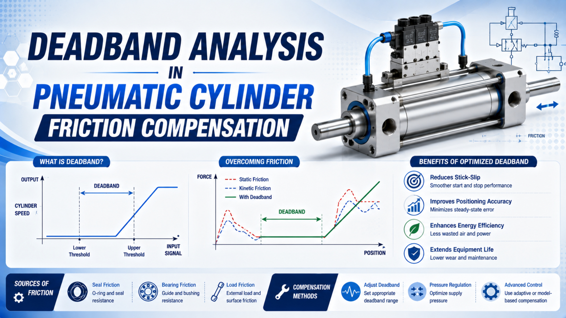
Pneumatic cylinder friction deadband is the measured input interval in which an actuator axis remains inside a declared motion threshold. Static friction can create that interval, but valve overlap, pressure buildup, load, sensor resolution, and control logic may contribute too. Treat it as a test boundary. A percentage is meaningful only when the tested input, output, span, direction, and threshold are named.
Measurement boundaries come first.
Key Takeaways
- A 2020 cylinder study synchronized 2 chamber pressures with position every 0.1 ms and repeated each condition 45 times.
- Breakaway friction must be calculated from both chamber pressures and effective piston areas.
- Compensation passes only when it reduces directional thresholds without adding creep, hunting, impact, or unsafe force.
This guide treats deadband as a measurement problem before treating it as a tuning problem. It separates the valve, pneumatic, mechanical, sensing, and controller layers so an offset intended to overcome seal friction is not used to hide a sticky spool, side load, pressure delay, or noisy position threshold.
What Does Deadband Mean in a Pneumatic Cylinder Axis?
Emerson’s 2023 control-valve handbook notes that many regulatory control actions are 1% of input span or smaller, which makes an inactive input interval operationally important. For a cylinder axis, however, the input and output must be declared before the same word can be used quantitatively (Emerson Control Valve Handbook, 2023).
An input might be PLC counts, valve command voltage, commanded pressure, or desired position. The observed output might be spool position, mass flow, chamber pressure, piston velocity, or load position. Name both. Each pair produces a different measurement boundary. Deadband is not automatically the same as hysteresis. Deadband describes an input interval traversed before the selected output responds. Hysteresis compares the outputs on rising and falling paths at the same input. Dead time is a time delay. Resolution is the smallest detectable change. Mixing these quantities makes compensation gains impossible to defend.
| Measurement | Input | Observed output | What the result includes |
|---|---|---|---|
| Command-to-spool deadband | Electrical valve command | Spool feedback | Driver, magnetics, spool overlap, valve friction |
| Command-to-pressure deadband | Electrical command | Chamber pressure | Valve behavior, supply, tubing, chamber volume, leakage |
| Command-to-motion deadband | Controller output | Piston or load motion | Valve, pressure buildup, friction, load, sensor threshold |
| Force-to-motion threshold | Net pneumatic force | First sustained motion | Cylinder and guide friction plus external resisting forces |
Ask “Between which input and output, under what load, and with what motion threshold was the inactive interval measured?” That is more useful than asking how much deadband a cylinder has.
Why Is Cylinder Friction Different From Valve Dead Zone?
SMC lists 0.5% full-scale hysteresis and ±0.2% full-scale sensitivity for its ITV1100/2100/3100 electro-pneumatic regulator family. Those are component-level pressure-control specifications, not cylinder-position guarantees. Axis motion adds tube volume, two chamber pressures, piston areas, seals, guides, load, feedback, and controller timing (SMC ITV, accessed 2026).
Troubleshooting depends on this distinction. A command can change without spool movement. Spool movement may still produce too little flow to alter chamber pressure. Pressure can change without net piston force exceeding the resisting load, and net force can rise while the position sensor still reports no motion.
For a detailed valve-level definition, use the separate guide to proportional valve deadband and control accuracy. This article stays with friction at the cylinder and installed-axis boundary.
How Does Static Friction Create a Motion Threshold?
Researchers testing a double-acting cylinder in 2020 used 3 supply pressures, 200, 400, and 500 kPa, and repeated every condition 45 times. Motion began when the pressure forces on the two piston faces overcame static friction, demonstrating why one supply-gauge reading cannot determine breakaway force (Experimental Techniques, 2020).
For extension, use gauge pressures referenced to the same atmosphere:
Here, is cap-end gauge pressure, is rod-end gauge pressure, is full piston area, and is rod-side annular area. At the first sustained extension movement, and with acceleration still negligible, the opposing static friction can be estimated as:
External resistance combines the declared load, gravity component, guide resistance, cable or hose force, and any other known extension-resisting force. Retraction reverses the pressure-area terms:
At retraction onset, the estimate becomes . Do not assume the two directions match. Rod-side area, seal geometry, side load, gravity, guide preload, and attached services can all create asymmetry.
Breakaway force is the net driving force at the declared onset of sustained motion. Direction matters. It is a test result for one direction and condition, not a fixed percentage of theoretical cylinder force. Static friction is also not a fixed coefficient multiplied by one known normal force. Pneumatic seals deform with pressure, lubrication films change with motion and dwell, and guide or alignment forces may vary across the stroke. The 2026 stick-slip study explicitly added dwell-time dependence to its friction formulation because the restart peak changed with the sticking interval (Actuators, 2026). If a cylinder moves smoothly unloaded but sticks after tooling is installed, inspect guidance and alignment before increasing compensation. The side-loading guide explains why a control offset cannot replace an external guide.
Which Signals Should You Measure?
Researchers in the 2020 test placed 2 pressure sensors 5 cm from the chambers, measured position with an 85 µm-capable encoder, sampled the channels synchronously every 0.1 ms, and repeated each condition 45 times. Those settings are study-specific, but the synchronized signal set is transferable (Experimental Techniques, 2020).
Record the shortest signal chain that can isolate the fault:
- Position command and controller output. Keep engineering units and raw counts.
- Valve command and actual current. Current feedback shows whether the driver and coil followed the software output, including the moment direction changed.
- Spool feedback, pressure, or flow when available. Choose the variable closest to the suspected valve fault, and preserve its native range rather than converting every signal to percent.
- Both cylinder chamber pressures. A single trace cannot establish double-acting pressure-area force.
- Load position and derived velocity. Document the position datum, filter, differentiation method, detection threshold, and time alignment. Retain the unfiltered channel for review.
- Operating context. At minimum, log supply pressure, payload, orientation, and temperature. Add regulator output, valve state, flow-control settings, cycle history, dwell, and stroke location when those variables change during the test.
Use a sampling rate that resolves the shortest event of interest with margin. A 100 Hz logger may be adequate for a slow commissioning ramp yet miss fast valve current changes. Higher sampling does not fix a long pressure-sensor tube, unsynchronized clocks, noisy differentiation, or a position transducer mounted on a flexible bracket. Movement detection also needs a rule. One practical definition declares movement when displacement exceeds and remains beyond it for a hold time . Publish both values; otherwise, changing a software filter can appear to change deadband even though the mechanics did not change.
How Do You Calculate Axis Deadband?
In one 2020 test condition, measured command-to-motion latency was 0.026 s at 400 and 500 kPa and 0.029 s at 200 kPa. Those are time delays for that bench, not deadband percentages. They illustrate why inactive command width and elapsed response time must be calculated and reported separately (Experimental Techniques, 2020).
Run a slow positive and negative command sweep while recording the declared output. Use native units. Let be the positive-direction command at first sustained motion and the negative-direction threshold. The central inactive command width is:
If a normalized value is genuinely useful, state the tested input span:
This percentage belongs to that input scale and detection rule. Never infer stroke error from it. A controller may integrate through the inactive interval, settle within a tolerance window, or oscillate across the thresholds. Calculate the pressure-area breakaway force in each direction at the exact motion onset as well. Comparing with and separates two changes that otherwise look alike:
| Test result | Likely interpretation |
|---|---|
| Command threshold changes, breakaway force stays similar | Valve, electronics, scaling, or pressure buildup changed |
| Breakaway force rises in one direction | Alignment, guide load, seal condition, gravity, or attached services changed |
| Both thresholds drift after long dwell | Seal/lubrication state or dwell-dependent friction may be involved |
| Pressure oscillates before every slip | Compressibility and valve flow are interacting with friction |
| Position moves but the detector remains inactive | Sensor threshold, filtering, backlash, or mounting is hiding motion |
Worked example: compare command thresholds before and after compensation
For example, suppose an axis uses a -10 to +10 V command. Keep the span explicit. Document it. Sustained positive motion begins at , while negative motion begins at . The measured central width is:
Relative to the declared 20 V span:
These are illustrative inputs, not a cylinder specification. If compensation changes the thresholds to +0.3 V and -0.2 V, the width falls to 0.5 V, or 2.5% of the same span. Accept the change only if independent cycles also show stable settling, acceptable peak force, and no creep, chatter, or impact.
Command deadband and breakaway force are complementary measurements. Tracking only one cannot show whether compensation corrected the input path or merely pushed harder against a mechanical problem.
Friction Models and Compensation Methods
Canudas de Wit and colleagues introduced a one-state friction model in 1995 to represent average bristle deflection, presliding displacement, the Stribeck effect, and hysteresis. A 2018 pneumatic-positioning study then applied LuGre-based friction compensation to a servo-pneumatic axis (IEEE, 1995; Journal of Mechanical Engineering, 2018).
Friction compensation is a bounded controller term or estimated disturbance used to counter an identified friction effect. It is not permission to increase force until a mechanically constrained axis moves.
Model complexity should follow the motion requirement and available measurements.
| Method | What it represents | Suitable use | Main risk |
|---|---|---|---|
| Directional offset | Separate positive and negative breakaway commands | Repeatable hardware, modest accuracy, slow changes | Overcompensation after friction changes |
| Coulomb plus viscous model | Direction-dependent constant term plus velocity term | Motion away from zero velocity | Poor presliding and reversal behavior |
| Stribeck curve | Higher low-speed friction that falls toward Coulomb friction | Low-speed feedforward with identified data | Sensitive to velocity estimation near zero |
| LuGre or extended model | Presliding state, Stribeck behavior, hysteresis | Servo axes with identification and validation resources | More parameters, state estimation, and tuning effort |
| Disturbance observer | Estimates combined unmodeled force online | Systems with reliable dynamic model and feedback | Can confuse load change with friction |
| Dither | Small alternating command intended to avoid sticking | Only where valve, mechanics, noise, wear, and safety permit | Heat, vibration, wear, audible noise, unwanted motion |
A common static model is:
In this model, is the identified static-friction level, the Coulomb level, the Stribeck velocity scale, a shape exponent, and the viscous coefficient. The sign function makes this equation discontinuous at zero unless the implementation adds a transition rule. Identify parameters from the actual axis instead of borrowing them from another seal, bore, lubricant, load, or temperature.
An observer-based pneumatic study used an inner pressure loop, outer position loop, friction observer, and velocity observer, then adjusted desired pressure from the estimated friction force (JSME, 2009). That architecture shows why compensation should enter a defined control layer rather than as an unexplained PLC output jump.
How Should Compensation Be Commissioned?
Researchers compared 3 pneumatic cylinders in 2026 and measured position, velocity, 2 chamber pressures, and inferred friction under changes in flow, supply pressure, load, and initial position. System-level coupling, not velocity-only friction, governed the repeated sticking and slipping (Actuators, 2026).
Commission compensation in controlled stages:
- Make the mechanics credible. Verify alignment, guides, side load, end stops, seals, and lubrication policy before touching controller gains.
- Stabilize the pneumatic supply. Record dynamic supply and both chamber pressures. Confirm tube routing, meter-out settings, and exhaust back pressure while the real payload moves.
- Validate sensing. Check polarity, scale, zero, mounting stiffness, noise, time alignment, and the movement detector. An offset fitted to a loose encoder bracket is not friction compensation.
- Capture a baseline. Run slow bidirectional ramps with repeated holds.
- Choose the smallest adequate model. Directional breakaway terms may be enough for repeatable hardware. Add velocity dependence or dynamic states only when residuals remain structured across independent cycles.
- Bound every added term. Define output and rate limits, integrator management, reversal logic, and safe fallback behavior when a pressure or position signal becomes invalid.
- Retest beyond the identification cycle. Change dwell first. Then cover direction, stroke position, payload, supply pressure, speed, and the approved temperature range without re-identifying parameters between every run.
Keep the air-compressibility control effects separate from the friction model. Stored energy still matters. Pressure can continue building while the piston sticks, then release pneumatic energy during slip. Increasing a friction offset without examining that energy can make the first movement harsher.
Failure Patterns That Compensation Cannot Fix
Researchers observed stick-slip across 3 cylinders in 2026 while varying airflow, supply pressure, external load, and initial piston position. That test matrix warns against one universal correction value: similar jerky motion can arise from different combinations of pressure buildup, valve flow, chamber volume, friction, and load (Actuators, 2026).
| Trace pattern | Likely path | Action before retuning |
|---|---|---|
| Controller output is flat or clipped | PLC scaling, dead zone, limit, or interlock | Inspect command generation and output limits |
| Current changes but spool or flow does not | Valve driver, coil, spool overlap, contamination | Test valve-level input and output variables |
| Pressure rises slowly in both directions | Undersized valve/tube, supply sag, leakage, large volume | Review dynamic pressure and flow path |
| One direction needs much more breakaway force | Side load, guide preload, gravity, seal asymmetry | Correct mechanics and calculate directional forces |
| Breakaway force changes with stroke position | Barrel, guide, alignment, attached hose/cable | Map friction across the full working stroke |
| Regular pressure ramps precede sudden slips | Compressibility and flow interact with friction | Review meter-out control and low-speed stability |
| Compensation causes alternating corrections | Excess gain, offset, delay, or integrator windup | Reduce bounded terms and review loop timing |
| Friction grows after idle time | Dwell-dependent seal or lubrication behavior | Include dwell in identification and acceptance |
Meter-out settings can stabilize low-speed motion, but excessive exhaust restriction raises back pressure and changes available force. The meter-out speed-control guide covers that pneumatic layer. For repeated low-speed jumps, compare the trace with the dedicated stick-slip analysis. Never use compensation to push through a mechanical bind: it converts a detectable maintenance problem into higher seal, bearing, guide, or tooling load. Likewise, a controller that reduces final position error while increasing impact speed or peak force has not improved the whole axis.
A Practical Validation Record
ISO 19973-3:2015 treats pneumatic-cylinder reliability using cycles or kilometres and prescribes test and reporting procedures for rod cylinders. It does not provide a universal 6-month or 1-million-cycle deadband interval. Risk sets the interval. Maintenance and revalidation frequency must follow observed drift, cylinder data, and the machine duty profile (ISO, 2015).
Record enough information for another engineer to repeat the result:
- identify the cylinder by manufacturer, model, bore, rod diameter, stroke, mounting, guide, and seal option;
- record the valve and driver models plus the native command scale;
- describe payload, orientation, external forces, tooling, attached hoses or cables, and every tested stroke position. Include dynamic supply pressure, regulator behavior, tubing, and flow-control settings when they influence the trace;
- document pressure-sensor models and port locations. For position sensing, include resolution, mounting, sample rate, filters, differentiation, and channel time alignment;
- state the motion threshold , hold time , ramp rate, direction, dwell, cycle history, and temperature;
- report and in native units. Add , , uncertainty, repeat count, and acceptance limits when pressure-area force was calculated;
- preserve the controller version, compensation parameters, clamps, reversal logic, fault behavior, and the independent cycles used for final acceptance.
Useful deadband records preserve the boundary and uncertainty instead of reducing a machine to one percentage. One axis can legitimately produce different values when the input, output, dwell, load, direction, or detection threshold changes.
When theoretical cylinder force is part of the review, the pneumatic cylinder force guide provides the pressure-area baseline. Deadband work must then add measured back pressure, load, gravity, and breakaway friction rather than applying a generic friction percentage. Publisher and author context is available on About Us. To request a model-specific trace review or submit a technical correction, send the cylinder, valve, load, sensing, and synchronized pressure data through Contact.
Pneumatic Cylinder Deadband FAQs
Two experiments establish the repeatability problem: the 2020 study repeated each condition 45 times, while the 2026 study compared 3 cylinders and several operating variables. A defensible answer must therefore name the hardware, direction, load, pressure, dwell, detection rule, and measured input-output pair (Experimental Techniques; Actuators).
Is pneumatic cylinder deadband normally 5-15%?
No universal 5-15% range applies. A percentage changes with the selected input span, observed output, direction, load, valve, pressure path, sensor threshold, and test method. Report the positive and negative movement thresholds in native units first, then normalize only to a clearly stated command span when comparison requires it.
Can PID tuning eliminate static friction deadband?
PID action can integrate until motion begins, but it does not remove static friction. That distinction matters. Excess integral or proportional gain can drive the axis through the threshold and create overshoot or hunting. Correct mechanical causes first, then use bounded feedforward, friction estimation, or an observer while retaining stable feedback and anti-windup behavior.
Why are both chamber pressures required?
Double-acting cylinders develop force from pressure acting on two different effective areas. Supply pressure alone omits rod-side back pressure and dynamic pressure loss. Recording both chamber pressures at motion onset lets the engineer calculate directional pressure-area force and distinguish rising mechanical friction from a valve, supply, or exhaust restriction.
Should a dither signal be added to every sticky axis?
No. Dither can reduce sticking in some valves or mechanisms, but it can also produce unwanted motion, noise, heat, wear, and pressure oscillation. Use it only when the component and safety analysis permit it, then validate amplitude and frequency across load, dwell, temperature, and the complete operating envelope.
How often should deadband be remeasured?
Measure it during commissioning, after relevant hardware or software changes, and when trends show new delay, asymmetry, hunting, or breakaway force. Trend the result. A fixed calendar or cycle interval requires manufacturer guidance or machine-specific reliability evidence. ISO 19973-3 addresses cylinder reliability testing but does not prescribe one universal deadband-check interval.
Sources and technical references
- Ngoc, Pham, and Xuan, Experimental and System-Level Simulation Study of Stick-Slip Characteristics in Pneumatic Cylinders, three-cylinder system-level stick-slip experiments and friction modeling; Actuators, 2026. Retrieved 2026-07-23.
- Jiménez, Kurmyshev, and Castañeda, Experimental Study of Double-Acting Pneumatic Cylinder, synchronized chamber-pressure and displacement measurements with repeated trials; Experimental Techniques, 2020. Retrieved 2026-07-23.
- Canudas de Wit et al., A New Model for Control of Systems with Friction, LuGre friction-model foundation; IEEE Transactions on Automatic Control, 1995. Retrieved 2026-07-23.
- Wei et al., Control of Pneumatic Position Servo with LuGre Model-based Friction Compensation, pneumatic position-control application of LuGre compensation; Journal of Mechanical Engineering, 2018. Retrieved 2026-07-23.
- Kosaki and Sano, An Observer-Based Friction Compensation Technique for Positioning Control of a Pneumatic Servo System, pressure-loop and friction-observer architecture; Journal of System Design and Dynamics, 2009. Retrieved 2026-07-23.
- Emerson, Control Valve Handbook, deadband definition and control-loop context; 6th edition, 2023. Retrieved 2026-07-23.
- SMC, ITV1100/2100/3100 Electro-Pneumatic Regulator, model-family sensitivity, linearity, and hysteresis specifications. Retrieved 2026-07-23.
- ISO 19973-3:2015, pneumatic rod-cylinder reliability test and reporting scope. Retrieved 2026-07-23.