

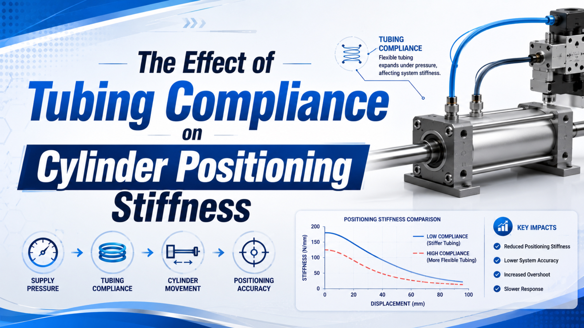
Tubing compliance reduces cylinder positioning stiffness because every connected air volume must change pressure when the piston moves under load. Usually, calculate trapped gas volume first. Treat tube-wall expansion as a separate effect that needs product-specific data or a controlled measurement. Positioning stiffness is not repeatability, static friction, sensor resolution or servo accuracy. Call it the local force-to-displacement ratio around one operating point. Measure that point with the valve state, chamber pressures, piston position and controller mode documented; without those conditions, a stiffness value cannot be reproduced.
Key Takeaways
- Ten metres of SMC 8 mm OD, 5 mm ID tube contains about 196 cm³ of air.
- Add tube and fitting volume to the connected cylinder chamber before calculating gas stiffness.
- Use absolute pressure and evaluate both chambers.
- Select tube ID from both stiffness and ISO 6358 flow requirements.
Our broader air-compressibility guide explains pressure dynamics during motion. This article focuses on small load disturbances near a held position and shows why tube inside diameter, not the outside label alone, changes the result.
What Does Tubing Compliance Mean in a Pneumatic Positioning System?
SMC identifies its TU0805 polyurethane tube as 8 mm outside diameter and 5 mm inside diameter, with a maximum operating pressure of 0.8 MPa at 20°C (SMC TU0805 web catalog, accessed 2026-07-23). Those dimensions determine trapped air volume; they do not quantify tube-wall expansion.
Pneumatic line compliance is the change in stored air volume associated with a pressure change between the control valve and a cylinder chamber. It has two parts that should not be merged into a dimensionless material multiplier:
- Gas-volume compliance: the pressure response of the trapped compressed air in the cylinder chamber, port, fitting and tube.
- Tube-wall compliance: the additional internal-volume change caused by elastic expansion of the tube wall under pressure.
For a closed gas volume undergoing a small polytropic pressure change, the gas-volume compliance is
In this expression, is volumetric compliance in m³/Pa, is the effective connected gas volume, is the polytropic exponent, and is absolute pressure. A slow, heat-exchanging disturbance tends toward an isothermal model with near 1. A rapid disturbance is commonly modelled closer to the adiabatic value for air.
Tube-wall compliance can be written as a local slope:
Adding the gas and wall terms gives chamber compliance . Its small-signal stiffness contribution is then
Match effective area to its chamber. In a single-rod cylinder, cap-side piston area is larger than rod-side annular area, so the model needs separate values. Only rodless or double-rod geometry with equal working areas supports an equal-area assumption.
The useful distinction is volume first, material second. Tube length and ID define a calculable gas volume. Tube material alone does not reveal wall-volume change. If a supplier does not publish pressure-versus-volume data, keep wall compliance as an unknown to be measured rather than inserting an unsupported polyurethane correction factor.
Why Does Tube Volume Reduce Cylinder Positioning Stiffness?
Published in 2024, a pneumatic-actuator study places cylinder dead volume and tube volume directly in the denominator of both chamber-stiffness terms (Actuators, accessed 2026-07-23). Added connected volume reduces pressure change for a given piston displacement, so the pneumatic spring becomes softer.
Tube volume follows the ordinary cylinder-volume relationship:
Use actual tube inside diameter for and valve-to-port length for . Outside diameter is not a substitute. Add fitting cavities, end-cap passages and manifold galleries separately when they are large enough to matter.
At position , a double-acting cylinder has connected volumes represented as
Dead-volume terms and include cylinder passages and fitting cavities, while is stroke. If tube-wall expansion is temporarily neglected, the two gas-spring contributions add:
This equation describes a small disturbance around a stated position with trapped chamber masses. It cannot predict a complete servo move by itself. Open valves change mass flow; controllers change commanded flow; seals add friction and hysteresis. Rad and Hancu’s 2017 open-access servo-pneumatic model therefore treated dead volume, valve dead zone, heat transfer and nonlinear friction as separate effects instead of folding them into one stiffness number (Simulation Modelling Practice and Theory, 2017).
Natural frequency also depends on moving mass:
Moving mass includes the piston, carriage and reflected load. Lower stiffness reduces this ideal undamped natural frequency, but settling time and overshoot still depend on damping, valve dynamics, friction and the controller. Such a ratio alone cannot justify a claimed frequency or positioning improvement. Command-to-first-motion delay from the same line volume has a different boundary, covered in the response-time and dead-volume analysis.
Flow-limited motion needs the separate hose and fitting sizing guide. One tube must satisfy both problems.
A Corrected 10 m Tubing Example
SMC’s 8 mm OD, 5 mm ID specification gives 196.35 cm³ of trapped volume in a 10 m tube, not 503 cm³ (SMC TU0805, accessed 2026-07-23). Obtaining the larger value requires an 8 mm inside diameter. This example keeps every diameter and pressure basis explicit.
Assume an equal-area rodless cylinder with these values:
| Input | Value | Reason |
|---|---|---|
| Bore diameter | 40 mm | Gives equal effective area in this simplified rodless example |
| Stroke | 300 mm | Piston evaluated at mid-stroke |
| Tube on each chamber | 10 m, 5 mm ID | Valve is remote from the cylinder |
| Dead volume per chamber | 10 cm³ | Stated engineering assumption |
| Pressure in each chamber | 7 bar absolute | Equivalent to about 6 bar gauge near sea-level atmosphere |
| Polytropic exponent | 1.4 | Rapid small-disturbance assumption |
| Applied disturbance | 20 N | Used only to compare ideal elastic deflection |
Piston area is
At mid-stroke, the geometric chamber volume is
Tube volume on each side is
Without the remote tube, each modelled chamber contains . Remote tubing nearly doubles it to . Compare the results below.
| Result | Valve close to cylinder | 10 m tube on each side |
|---|---|---|
| Effective volume per chamber | 198.50 cm³ | 394.85 cm³ |
| Calculated two-chamber stiffness | 15.59 kN/m | 7.84 kN/m |
| Relative stiffness | 100% | 50.3% |
| Ideal deflection under 20 N | 1.28 mm | 2.55 mm |
Treat these values as calculations from the stated assumptions. They omit tube-wall expansion, seal friction, structural compliance, valve leakage and controller action. Change piston position, tube ID, pressure, dead volume or valve state and the force-displacement response can move far enough to reverse a component decision.
The example becomes soft because tube volume is almost equal to chamber-plus-dead volume on each side. Doubling effective volume nearly halves the gas stiffness under fixed pressure and polytropic assumptions. That proportional result does not apply when one chamber, friction, an active valve or a mechanical stop dominates the response.
Why an 8 mm Tube Label Cannot Predict Stiffness
Outside diameter alone cannot define trapped volume. SMC’s TU0805 lists a 5 mm ID, whereas Festo’s PUN-H-8X1.25 lists 5.7 mm (SMC; Festo, accessed 2026-07-23). That ID difference raises 10 m tube volume from 196 to 255 cm³, about 30% before wall expansion is counted.
This difference appears before any tube-wall movement is considered. Tube specifications should therefore record at least five separate properties:
| Property | Why it matters to stiffness | Why it is not interchangeable |
|---|---|---|
| Outside diameter | Selects push-in fitting and available wall envelope | Does not determine internal volume |
| Inside diameter | Sets trapped air volume and affects flow area | Can differ between products with the same OD |
| Length | Multiplies tube volume directly | Routing length is often longer than drawing distance |
| Material and construction | Affect wall response, bending and temperature limits | Material name alone does not provide volume-pressure slope |
| Pressure and temperature rating | Defines approved operating envelope | A pressure rating is not a compliance curve |
Festo identifies the PUN-H-8X1.25 as TPE-U polyurethane with a 5.7 mm ID, Shore D 52 +/-3 and an 8 mm OD. Those figures aid product selection. Neither they nor SMC’s geometry and operating-pressure values state . For a high-value positioning application, obtain a supplier pressure-versus-volume curve or measure the assembly. One laboratory method fills the isolated tube with a low-compressibility liquid, controls temperature, records injected volume against pressure and subtracts fixture compliance. A practical machine test compares otherwise identical circuits with a short rigid reference line and the production tube. Repeat it at the application’s temperature limits because polymer response and gas density both change.
Do not convert bulk resin Young’s modulus directly into installed tube compliance unless the tube model accounts for actual wall thickness, Poisson response, reinforcement, fittings, temperature and nonlinear material behaviour. Generic polyurethane ratios are not product specifications.
Use the pneumatic tubing routing guide to determine actual installed length. Measure the path after bends and service loops rather than using the straight-line machine-layout distance.
How Should You Measure Positioning Stiffness on the Machine?
Rad and Hancu’s 2017 servo-pneumatic validation reported mean absolute chamber-pressure error below 0.04 bar outside the valve-centre dead zone after identifying system parameters (open-access paper, accessed 2026-07-23). Their result supports measuring dead volume, pressure and friction separately instead of attributing every position change to tubing.
Start by defining the held state. Three cases behave differently: a closed-centre valve with isolated ports, a pressure-controlled servo hold and a mechanical stop. Record the valve centre condition, command signal and controller gains. Nominal centre position does not guarantee zero leakage or fixed chamber mass, as the 5-way, 3-position valve guide explains.
Use this repeatable test sequence:
- Stabilize. Reach normal supply pressure and tube temperature.
- Choose a piston position. Test at 10%, 50% and 90% of stroke when the application uses the full travel.
- Record both chamber pressures. Use synchronized sensors close to the cylinder ports and convert gauge readings to absolute pressure for the model.
- Apply controlled load steps. Mount the force sensor at the real load point, then increase and decrease external force around the operating point without reaching a stop, twisting the guide or breaking static friction violently.
- Measure actual load-point displacement. A cylinder sensor may not capture carriage, bracket or guide deflection.
- Fit the local slope. Use several points in each direction and report hysteresis rather than selecting one convenient pair.
Measured system stiffness is
System-level includes pneumatic, tube-wall, mounting, guide and structural effects. A flexible bracket, for example, can lower measured load-point stiffness even when both pressure traces match the pneumatic model. Seal friction creates distinct loading and unloading paths, so a single secant value can hide hysteresis. Compare both slopes before diagnosing the line. To isolate line effects, repeat the test at the same cylinder position, chamber pressures, controller state and load fixture after installing the shortest practical reference connection. That change represents the complete line assembly, including fittings and wall behaviour; do not label it pure tube-wall compliance until gas-volume and fixture effects have been removed.
When force balance is also under investigation, use synchronized pressure traces and the dual-port cylinder force-loss method. It prevents seal friction and rod-side back pressure from being counted twice.
Design Changes That Protect Stiffness and Flow
Moving the valve closer cuts trapped volume, but shrinking tube ID is safe only after a flow check. ISO 6358-1 defines steady-state compressible-flow testing for pneumatic components and excludes cylinders and accumulators (ISO 6358-1, confirmed 2022; Amendment 2 issued 2026). Use both volume and conductance data, not tube OD alone.
Prioritize changes in this order:
- Remove loops. Shorter routing reduces volume without changing flow area.
- Move the directional or proportional valve closer. A local valve island or cylinder-mounted valve shortens both chamber lines.
- Reduce fitting cavities and manifold galleries. Include them in the volume ledger before changing tube material.
- Select ID from the complete flow path. Check target stroke time, required cylinder flow, fitting throat, bend radius, valve conductance and the actual upstream-to-downstream pressure ratio before reducing diameter.
- Retune the controller after hardware changes. Changing volume changes pressure dynamics and the plant seen by a servo controller.
- Use a mechanical lock when holding is safety-related. Pneumatic stiffness and a closed-centre spool are not positive mechanical restraint.
Screen velocity and diameter with the tube ID calculator, then estimate target stroke flow through the cylinder flow requirement calculator. Even then, the final circuit needs model-specific ISO 6358 conductance data and a dynamic pressure test. An accumulator upstream of the control valve can buffer supply-pressure sag during a flow transient; it does not automatically stiffen a sealed cylinder chamber. Directly connecting an accumulator to a held chamber adds gas volume and can lower that chamber’s static pneumatic stiffness. Circuit location decides the effect.
Pressure feedback rejects some slow load disturbances. Position feedback commands corrective flow, but neither mode removes trapped volume. Valve dead zone, sensor resolution, friction, control bandwidth and stability margin together determine whether the active hold remains useful. The proportional-valve positioning guide covers that design.
If loss of air or leakage could release the load, use a rod lock, brake, stop or other risk-assessed holding device. Our rod-lock safety guide separates positioning control from load retention.
The best first modification is the one that removes volume without consuming flow margin. Shortening a 5 mm ID tube removes about 19.6 cm³ per metre. For instance, removing a 5 m service loop eliminates about 98 cm³ of trapped volume. Reducing ID changes volume faster because volume scales with diameter squared, but it also changes velocity and pressure drop. Length reduction is usually the cleaner first experiment.
What Belongs in a Positioning-Stiffness Test Report?
Researchers in 1999 examined supply pressure, regulator size and extra upstream volume in one position-servo test programme, noting about 7 bar absolute as typical industrial supply (Virvalo and Mäkinen, 1999). Useful reports likewise record the complete pneumatic boundary, not tube material alone.
Use a table that allows another engineer to reproduce the operating point:
| Report field | Minimum detail |
|---|---|
| Cylinder | Type, bore, rod diameter if present, stroke and mounting |
| Position | Distance from a defined end and percentage of stroke |
| Load geometry | Force direction, load point and guide arrangement |
| Tube side 1 | Product, OD, ID, measured length and fitting count |
| Tube side 2 | Product, OD, ID, measured length and fitting count |
| Valve state | Model, centre condition, command and controller mode |
| Pressures | Both cylinder-port pressures, supply pressure and atmospheric reference |
| Temperature | Ambient and tube temperature after stabilization |
| Load steps | Positive and negative increments with dwell time |
| Displacement | Sensor type, resolution and measurement point |
| Result | Loading slope, unloading slope, hysteresis and uncertainty |
Report tube volume on each side, not one combined number. Near an end of stroke, a long line connected to the smaller chamber can dominate that side’s effective volume, while the opposite chamber still contributes substantial stiffness. Keep piston position and both pressures beside the final value. Separate theoretical pneumatic stiffness from measured machine stiffness as well. If the measured value is lower, investigate tube-wall expansion, valve leakage, seal hysteresis, bracket flex, guide clearance and load-frame compliance. Never assign the entire difference to a single cause without an isolation test.
Tubing Compliance FAQs: What Should Engineers Check?
SMC and Festo both sell nominal 8 mm OD polyurethane tube, yet the cited products use 5.0 and 5.7 mm IDs. That difference produces about 30% more volume over the same 10 m length (SMC; Festo, accessed 2026-07-23). These answers keep geometry, flow and wall elasticity separate.
Is flexible polyurethane tubing unsuitable for positioning systems?
No. Suitability depends on connected volume, published pressure limits, measured wall response, required flow and control bandwidth. Short polyurethane lines may be entirely adequate, while long rigid lines can still add substantial trapped gas volume. Calculate tube volume first, then verify dynamic response and load-point stiffness on the assembled machine.
Does a larger tube always reduce positioning stiffness?
At fixed length, a larger ID adds trapped volume and therefore reduces ideal gas stiffness when all other terms remain constant. It may also reduce flow restriction and improve stroke response. Choose diameter as a tradeoff: calculate chamber stiffness, required flow, fitting throat and valve conductance instead of optimizing only one variable.
Can a local accumulator increase cylinder stiffness?
Not when it is directly connected to an isolated working chamber. Added gas volume normally lowers that chamber’s static pneumatic stiffness. An accumulator placed upstream of the control valve can stabilize supply pressure during peak flow, which may improve dynamic consistency, but that is different from increasing closed-chamber positioning stiffness.
At which piston position is pneumatic stiffness lowest?
In a symmetric equal-area cylinder with similar pressures and small dead volumes, total two-chamber stiffness is commonly lowest near mid-stroke because both chambers are relatively large. Single-rod geometry, unequal pressures, unequal tube lengths and controller action shift the minimum. Calculate both chamber terms at the actual operating positions rather than applying a universal location.
How can I isolate tubing effects from seal friction?
Apply several small load steps in both directions while recording load-point displacement and both chamber pressures. Loading-unloading hysteresis exposes friction. Repeat the test with a short reference connection. Differences between the matched configurations estimate the complete line effect without assuming a material percentage.
Sources and technical references
- Energy Efficiency of Pneumatic Actuating Systems with Pressure-Based Air Supply Cut-Off, Actuators, 2024. Retrieved 2026-07-23.
- An improved nonlinear modelling and identification methodology of a servo-pneumatic actuating system, Simulation Modelling Practice and Theory, 2017. Retrieved 2026-07-23.
- SMC TU0805 polyurethane tubing web catalog. Retrieved 2026-07-23.
- Festo PUN-H-8X1.25 polyurethane tubing technical data. Retrieved 2026-07-23.
- ISO 6358-1:2013 and published amendments. Retrieved 2026-07-23.
- The Influence of the Supply Line on the Performance of a Pneumatic Position Servo System, 1999. Retrieved 2026-07-23.