

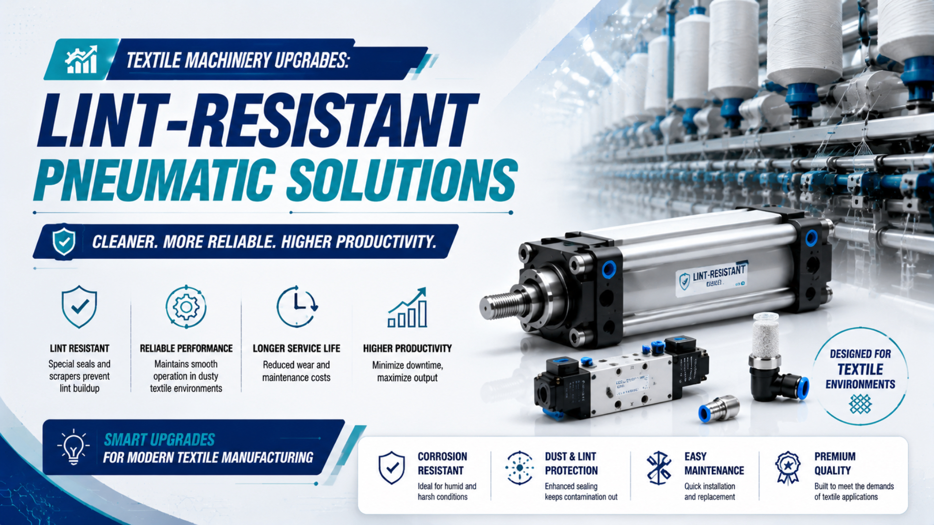
Lint resistance is not a universal cylinder rating. A reliable textile-machine upgrade starts by identifying where fibers reach moving surfaces, guides, exhausts, and seals. It then matches each contamination path to a model-specific countermeasure and proves the choice at the machine’s actual load, speed, stroke, and cleaning interval.
Key Takeaways
- OSHA’s 0.2-0.75 mg/m³ cotton-dust limits protect workers; they don’t rate pneumatic components.
- A scraper, closed tube, or air filter controls one contamination path, not the entire assembly.
- Require exact model data, then compare leakage, speed, cleaning time, and failures during a controlled production trial.
There is no honest shortcut here. A cylinder described as “heavy duty” may still expose a guide bearing, while a sealed pressure tube may still have an external carriage that traps fibers. The useful question isn’t whether a component sounds lint-resistant. It is whether the complete installed assembly controls the contamination paths present at that textile-machine position.
Why Does Textile Lint Defeat Standard Pneumatic Hardware?
OSHA’s current cotton-dust standard sets eight-hour limits of 0.2 mg/m³ for yarn manufacturing, 0.5 mg/m³ for specified waste-house work, and 0.75 mg/m³ for slashing and weaving. Those are worker-exposure limits, not cylinder ratings, but they demonstrate that textile dust conditions vary materially by process (OSHA, Cotton Dust Standard, accessed 2026).
Failures begin when the local contamination path and the component design don’t match. Exposed rods collect fibers. On every return stroke, a conventional rod cylinder can pull that loose material toward the wiper, where compacted deposits raise friction, damage the wiping edge, and hold abrasive particles against the rod surface. Misalignment further concentrates contact pressure and accelerates wear.
Valves and accessories have different exposure paths. A silencer can become loaded with fibers, an open exhaust can disturb deposited lint, and an enclosure can overheat a solenoid if ventilation is reduced without checking coil temperature. Tubing, fittings, switches, cable carriers, and manual overrides also create ledges where fibers accumulate.
Don’t diagnose every slow actuator as “lint inside the cylinder.” Measure first. Compare upstream pressure, downstream pressure, command timing, stroke time, and leakage before opening the actuator. The separate guide to troubleshooting pneumatic cylinder faults explains how to distinguish contamination from restricted flow, poor cushioning, misalignment, and seal wear.
Which Contamination Paths Should an Upgrade Control?
ISO 8573-1 classifies compressed-air contamination by particles, water, and oil, but ambient lint on a rod or carriage exists outside that air-quality classification. That distinction matters. A textile upgrade needs two reviews: the air entering the pneumatic circuit and the fibers reaching the component from the machine environment (ISO 8573-1, 2010).
The broader dusty-factory contamination-control guide covers source control, supply-air treatment, and maintenance ingress across industries. Textile lint behaves differently. The narrower task here is to trace flexible fibers around rods, carriages, guides, exhausts, and frequent cleaning interventions.
Treat the installation as five connected contamination paths:
- Moving-surface entry. Rods, wipers, guide rails, bearings, and carriage gaps can collect or compact fibers. Check the direction of travel and whether a cleaning jet simply drives lint deeper into the mechanism.
- Pneumatic supply. Internal particles, liquid water, and oil can damage seals or create sticky deposits even when the outside of the cylinder looks clean. Specify air quality at the point of use.
- Valve exhaust. Exhaust flow can resuspend settled fibers or clog an exposed silencer. Remote exhaust may help, but added tubing can create backpressure and slow the actuator.
- Surface retention. Recessed fasteners, labels, sensor slots, grease films, and damaged coatings create places where lint remains after routine cleaning.
- Maintenance entry. Opening guards, replacing seals, applying lubricant, or using contaminated tools can introduce more debris than normal production.
A single feature cannot close all five paths. For example, a heavy-duty scraper can protect the rod interface, but it doesn’t clean a guide rail or correct wet compressed air. A point-of-use filter controls the supply path, but it doesn’t keep airborne fibers off the outside of the actuator.
Inspect both. For the supply side, use the ISO 8573-1 air-quality guide to specify particles, water, and oil separately. For the mechanical side, document what technicians actually find during cleaning: loose lint, compacted fiber, oil-bound deposits, corrosion, scoring, or damaged wiper lips.
Which Cylinder Features Actually Improve Lint Resistance?
SMC’s XC4 dust-resistant catalog separates designs by tested powder size: 20-50 µm for a two-lube-retainer version, 30-100 µm for a heavy-duty scraper plus retainer, and 50-100 µm for a scraper version. The ranges are model-specific selection data, not a universal textile-lint classification (SMC, Dust Resistant Cylinder XC4, accessed 2026).
Specifics matter. That example shows what useful evidence looks like. The supplier names the construction, particle range, bore availability, speed range, temperature range, and limitations. By contrast, labels such as “industrial,” “sealed,” or “low maintenance” don’t identify what was tested.
For a rod cylinder, review these options in order:
- Heavy-duty or metallic scraper: useful when dry fibers or abrasive particles reach the rod. Confirm whether the scraper and rod seal are replaceable and whether the option changes minimum pressure or friction.
- Rod boot or bellows: isolates more of the rod, but the cover needs room to compress and must not rub on guards. Folds can also retain fibers, so cleaning access still matters.
- Stainless or coated rod: may improve corrosion or wear resistance, but a coating doesn’t prevent lint from reaching a damaged wiper.
- External guide: removes side load from the cylinder rod and transfers moment loads through hardware designed to carry them. This matters because side loading changes seal contact, increases guide friction, and can turn a manageable contamination problem into rapid mechanical wear.
Check the load path first. Read the side-load failure guide before selecting a stronger scraper as the only fix. If the old rod shows one-sided scoring or the load twists during travel, correct the guide and alignment before changing seal hardware.
Where Do Magnetic Rodless Cylinders Fit?
Parker’s P1Z magnetically coupled family covers 16-40 mm bores, and its guided version uses four plain bearings on two guide rods. The pressure tube can remain closed along the stroke, but the external carriage and guide are still moving, exposed parts that require a lint-control plan (Parker, P1Z Rodless Pneumatic Cylinders, 2025).
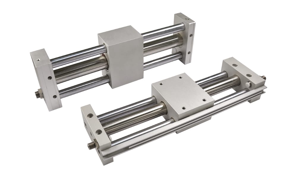
Magnetic coupling can keep the pressure tube closed, but exposed guide rods, bearings, and the external carriage still need cleaning and contamination controls.
Magnetic coupling is attractive where a long exposed piston rod would collect fibers or where a slot-type mechanically coupled rodless cylinder creates an unwanted opening along the stroke. It can also provide overload protection by decoupling before some mechanical parts are damaged.
It isn’t automatically the best choice. Available thrust is limited by both pneumatic force and magnetic coupling force. Acceleration, vertical load, guide friction, misalignment, temperature, and deposits in the carriage path can reduce operating margin. A decoupled carriage may also create a machine-recovery problem that the control sequence must detect.
Use the magnetic rodless cylinder guide for coupling, sealing, and breakaway checks. Use the rodless-cylinder mounting guide for alignment and load support. This article’s narrower decision is environmental: does the closed tube remove a dominant lint-entry path without leaving an unmanageable exposed guide?
Matching Pneumatics to Textile Machine Positions
NIOSH’s long-running textile study compared 447 cotton workers with 472 silk workers and followed exposure and lung function over decades. It is health research, not a pneumatic-component test, but it reinforces an important boundary: fiber type, process, and exposure history differ, so one plant-wide “lint-resistant” specification is too coarse (NIOSH, Lung Disease in Textile Workers, 2021).
Use a position-level matrix instead:
| Machine position | Dominant exposure | Motion concern | First engineering checks |
|---|---|---|---|
| Opening, carding, and spinning | Loose airborne fibers and frequent deposits | High cycling, rod and guide contamination | Scraper or cover, guide protection, cleaning access, stroke-time baseline |
| Doffing and package handling | Fiber deposits plus impact and changing payload | Alignment, cushioning, end-position repeatability | External guide, cushion energy, sensor protection, decoupling recovery |
| Weaving and knitting | Process-dependent dust with rapid repetitive motion | Flow, vibration, valve response, silencer loading | Valve location, remote exhaust, tubing length, guide wear |
| Dyeing and finishing | Lower fiber load may combine with moisture, chemicals, and heat | Seal compatibility, corrosion, sensor temperature | Exact material and temperature data, washdown method, point-of-use air quality |
| Inspection and packing | Lower contamination but direct contact with finished fabric | Clean surfaces and controlled exhaust | Smooth cleanable layout, exhaust direction, lubricant and coating review |
Notice what the table doesn’t do: it doesn’t rank every spinning machine as severe or every finishing machine as mild. Measure the actual position. A guarded actuator below the product can see less fiber than an exposed cylinder above a transfer point in the same room.
Walk the line while it is producing the fabric and package mix that causes the most trouble. Photograph deposits before anyone cleans them. Ask operators when motion first becomes unstable, then compare that account with pressure and timing records. Maintenance technicians may describe a “bad seal” while the evidence shows a bent bracket, a clogged silencer, or sticky deposits created by oil carryover. Procurement may see identical mounting dimensions while the proposed option has a different scraper, speed limit, or switch-temperature range. Bringing those observations together prevents a component swap from hiding the real failure path.
What Belongs in a Lint-Resistance RFQ?
Parker’s P1F ISO 15552 catalog separates 1-10 bar operating pressure, a standard -20°C to 80°C range, a -10°C to 150°C high-temperature option, and a separate metallic scraper option. That structure shows why “high temperature and dust resistant” must identify the exact option combination (Parker, P1F Pneumatic Cylinders, 2025).
Send suppliers a buildable operating envelope:
- exact current model code;
- bore, stroke, rod thread, retracted and extended dimensions, including the available clearance behind guards and around cable carriers;
- load mass, load center, orientation, side load, and any external guide;
- working pressure at the cylinder during motion, not only compressor-room pressure;
- target extend and retract time, cycles per minute, shifts per day, dwell periods, and the machine timeout that declares an incomplete stroke;
- fiber type, observed deposit, cleaning method, humidity, chemicals, and temperature;
- required scraper, cover, rod material, grease, seal material, switch, and cable option;
- acceptable leakage and speed drift;
Ask for the exact datasheet and option drawing. A family brochure is not enough when the proposed suffix changes bore availability, temperature, scraper construction, sensor range, or speed. If a supplier claims IP67, request the complete product configuration and test basis; don’t transfer an enclosure rating from a switch or valve coil to an entire cylinder assembly.
For replacement projects, photograph the old nameplate, ports, mounts, rod end, sensors, and surrounding guards. Then record where lint actually accumulates. That evidence is more useful than asking for a “same-size heavy-duty cylinder” without describing the failure.
How Should You Validate the Upgrade on the Machine?
SMC’s XC4 catalog gives different maximum piston speeds for its dust-resistant constructions, including 1,000 mm/s for some versions and 700 mm/s for another. The envelope matters. A successful test must hold the selected model inside its published limits while reproducing the machine’s real load, deposits, and cleaning cycle (SMC, Dust Resistant Cylinder XC4, accessed 2026).
Run an A/B trial at one repeatable position. Before installation, capture upstream and downstream pressure, extend and retract time, leakage, end-position stability, and the minutes needed for cleaning. Record the same values after a defined number of shifts. Keep valve settings, payload, product, and operator cleaning method as consistent as production allows.
Consider a doffing actuator that becomes slow near the end of a production run: don’t begin by assuming the rod seal is at fault. Log the valve command and both end-position signals, measure pressure near the cylinder while it moves, inspect the exhaust silencer, and photograph deposits before cleaning. Next, verify that the load and guide move freely with the air isolated. Install the proposed configuration without changing unrelated valve settings, then repeat the same product sequence and inspection routine. If timing improves but pressure falls, the result points toward flow or exhaust restriction. If pressure remains stable while guide friction and cleaning time fall, the mechanical contamination control is doing useful work. This approach identifies what changed instead of crediting every improvement to the new cylinder. Keep the raw readings with the trial record so another technician can reproduce the comparison.
Inspect more than the seal:
- Before cleaning, photograph the rod, scraper, carriage, guide, sensor slot, exhaust, surrounding guard, and any deposit that could be disturbed during service.
- Classify its texture and chemistry.
- Check for one-sided wear, temperature rise, speed drift, pressure loss, leakage, and failed end-position signals.
- Record every intervention, including cleaning, alignment correction, lubrication, seal replacement, and valve or silencer service.
- Stop the trial if the actuator creates an unsafe motion, damages fabric, or cannot meet the machine’s recovery sequence.
Calculate MTBF only after defining what counts as a failure and keeping operating hours or cycles consistent. A cleaning intervention, seal leak, missed sensor, slow stroke, and complete cylinder replacement are not interchangeable events. Track them separately, then compare like with like.
Would a new cylinder still look successful if it needs twice as much cleaning time? Include maintenance minutes and production interruption in the acceptance result. Avoid projecting a three-year saving from a short pilot; state the observed test duration and leave the longer-term estimate conditional.
Textile Pneumatic Upgrade Checklist
ISO 8573-1 names three principal compressed-air contaminant groups, while Parker’s P1F documentation recommends a specific 3.4.3 air-quality class for that family. Keep them separate. Specify internal air quality and external lint protection independently, then confirm both at the installed point of use (ISO 8573-1, 2010; Parker P1F, 2025).
Before approving the upgrade, confirm:
- documented failure mode;
- ambient lint and compressed-air contamination have separate controls;
- mounting, alignment, side load, cushioning, and valve flow have been checked;
- every claimed scraper, temperature, speed, pressure, coating, or ingress feature belongs to the quoted model code;
- the carriage, guides, sensors, fittings, silencers, and cables are included in the review;
- cleaning access and a safe isolation procedure are available;
- a production trial has pass/fail limits for leakage, timing, position, maintenance time, fabric quality, and safe recovery after a missed stroke or magnetic decoupling;
- spare seals or replacement units match the tested configuration.
The rodless-cylinder preventive-maintenance checklist can support the post-installation schedule. Adjust its interval using inspection evidence. Calendar frequency alone can’t account for shifts, cycles, fiber type, cleaning method, or a changed production rate.
Conclusion: Specify the Contamination Path, Not the Label
SMC publishes dust-option particle ranges from 20 to 100 µm, while OSHA uses process-specific cotton-dust exposure limits from 0.2 to 0.75 mg/m³. The units and purposes differ. Together they show why a single “lint-resistant” claim cannot replace product data, an exposure map, and an installed trial (SMC XC4, accessed 2026; OSHA, current).
Start with the failed interface. If fibers pack around an exposed rod, examine scraper and cover options. If deposits restrict a guide, protect or relocate the guide. If exhaust resuspends lint, review valve location and backpressure. If internal deposits are wet or oily, correct compressed-air quality rather than blaming ambient dust, and confirm the result at the point of use under normal flow instead of relying on a compressor-room reading.
The best upgrade is the configuration that remains inside its published pressure, speed, temperature, load, and material limits while meeting a documented cleaning and maintenance target. Prove that at one machine position, then standardize only after the result repeats.
Textile Machinery Pneumatic FAQs
SMC’s dust-resistant catalog links construction to 20-100 µm powder ranges, and Parker’s magnetic P1Z family still uses an exposed guided carriage. These model-level facts answer the most common buyer questions: no single seal, IP label, filter, or cylinder architecture makes every textile-machine installation lint-resistant (SMC XC4, accessed 2026; Parker P1Z, 2025).
Is an IP67 rating enough for a textile-machine cylinder?
No. IP67 may describe a tested enclosure or a particular assembled product, but it doesn’t automatically rate exposed rods, guide rails, carriage bearings, fittings, silencers, or cleaning access. Request the exact model’s test basis and configuration, then review fiber accumulation and motion during an installed trial. Don’t infer assembly-level protection from one accessory’s rating.
Is a magnetic rodless cylinder always better in lint?
No. Magnetic coupling removes the mechanical slot used by some rodless designs and keeps the pressure tube closed along the stroke. Parker’s guided P1Z still has four plain bearings and two exposed guide rods, so carriage contamination remains possible. Check coupling margin, load guidance, acceleration, cleaning access, and recovery after decoupling before selecting it.
Will a five-micron air filter stop lint-related failures?
Not by itself. ISO 8573-1 addresses particles, water, and oil inside the compressed-air system. A supply filter doesn’t remove ambient fibers from a piston rod, scraper, guide, sensor slot, or valve silencer. Specify point-of-use air quality, then add separate external controls for the actual lint path observed at the machine.
How do I compare a dust-resistant cylinder with the current unit?
Compare complete model codes and option drawings, not family names. Record bore, stroke, mounting, rod thread, ports, load, side load, pressure, timing, speed, temperature, scraper, seals, sensors, and cleaning method. Then run both configurations against the same pass/fail limits for leakage, cycle time, positioning, maintenance minutes, and visible deposits.
What evidence supports a longer maintenance interval?
Evidence comes first. Use operating hours or cycles, defined failure categories, leakage results, stroke-time trends, cleaning minutes, and dated inspection photos. A short trial can justify the next inspection interval, but it cannot prove a multi-year life. Extend the interval gradually only when repeated inspections show stable seals, guides, pressure, motion, and fabric quality.
Sources and technical references
- OSHA. 29 CFR 1910.1043: Cotton Dust. Retrieved 2026-07-26. https://www.osha.gov/laws-regs/regulations/standardnumber/1910/1910.1043
- NIOSH. Lung Disease in Textile Workers. 2021. Retrieved 2026-07-26. https://www.cdc.gov/niosh/bulletin/2021/textiles.html
- ISO. ISO 8573-1:2010, Compressed Air: Contaminants and Purity Classes. Retrieved 2026-07-26. https://www.iso.org/standard/46418.html
- SMC Corporation. Dust Resistant Cylinder XC4. Retrieved 2026-07-26. https://www.smcworld.com/catalog/New-products-en/mpv/22-E781-DustResistant-XC4/data/22-E781-DustResistant-XC4.pdf
- Parker Hannifin. P1Z Rodless Pneumatic Cylinders. 2025. Retrieved 2026-07-26. https://www.parker.com/content/dam/Parker-com/Literature/Pneumatics-Division-Europe/PDE-Documents/Cylinders/Parker_Pneumatic_P1Z_Rodless_Pneumatic_Cylinders_PDE2522SLUK.pdf
- Parker Hannifin. P1F Pneumatic Cylinders. 2025. Retrieved 2026-07-26. https://www.parker.com/content/dam/Parker-com/Literature/Literature-Files/pneumatic/cat/english/0980-P1F-Pneumatic-Cylinders.pdf