

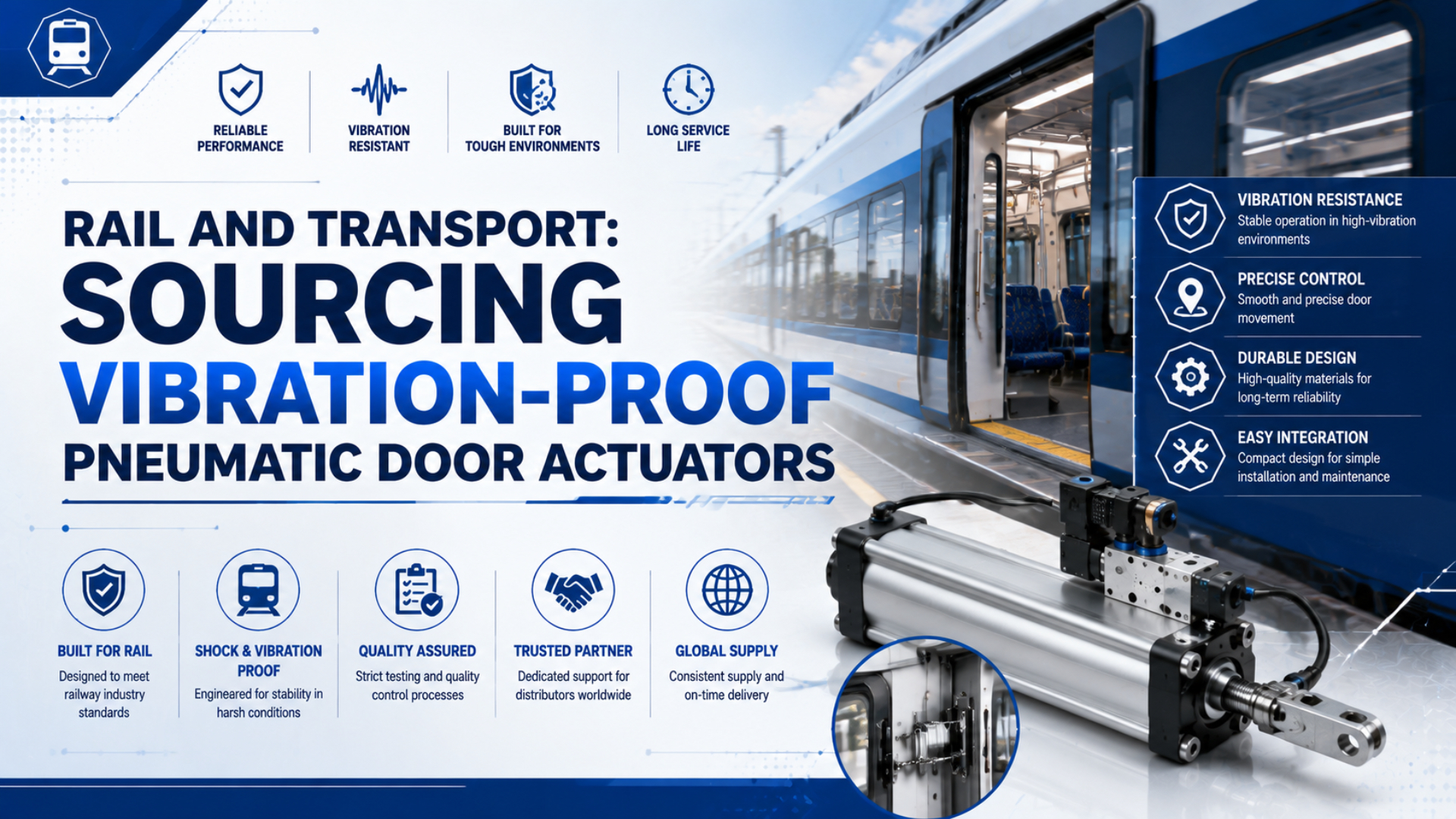
A “vibration-proof” pneumatic door actuator is not a universal product class. For rail use, the defensible choice is an exact actuator and mounting configuration supported by shock-and-vibration evidence for its installation location, then validated as part of the complete passenger-door system. A generic cylinder, reinforced-looking mount, or claimed g-rating isn’t enough.
The procurement boundary matters. Door motion depends on the actuator, mechanism, guides, valves, tubing, air supply, sensors, locks, control logic, emergency release, vehicle structure, and maintenance plan. Replacing one component can change closing force, timing, obstruction response, door status, and traction interlocking. Treat the replacement as a controlled system change.
Key Takeaways
- “Vibration-proof” requires configuration-specific IEC 61373 evidence.
- EN 14752 applies to the passenger entrance system, not a cylinder alone.
- Rail, road vehicle, and platform-door standards are not interchangeable.
- Match mechanical, pneumatic, control, safety, and environmental interfaces.
- Release a retrofit only after documented system-level verification.
What Does “Vibration-Proof” Mean for a Pneumatic Door Actuator?
IEC 61373:2026 replaced the 2010 edition on 17 July 2026 and defines shock-and-vibration testing for equipment installed on railway vehicles (IEC 61373, 2026). It does not create one universal continuous-g rating. Qualification depends on equipment location, configuration, orientation, spectra, test duration, function, and acceptance criteria.
The term vibration-proof pneumatic door actuator should therefore mean:
An identified actuator, mount, hardware set, valve and sensor configuration with traceable evidence that it satisfies the project’s mechanical environment and still performs its assigned door functions before, during, and after the required tests.
That definition excludes several weak shortcuts:
- a catalog described as “heavy duty” without a rail test report;
- a test performed on a different bore, stroke, mount, valve, sensor, or bracket;
- one peak acceleration value without frequency content, duration, axis, and mounting condition;
- a component that survives vibration but no longer meets leakage, timing, force, or position-indication limits;
- a successful bench test that omits the vehicle bracket, hose routing, door mechanism, or electrical connector;
- “designed to meet” language presented as completed compliance testing.
IEC 61373:2026 covers equipment attached to the main vehicle structure and components mounted on it. It also recognizes that customer-defined special environments may require additional tests. The vehicle location and installation are part of the requirement, not administrative details added after the actuator is selected.
From our analysis of the standard scopes, “vibration-proof” has two boundaries. The test boundary identifies what hardware was physically mounted on the shaker. The functional boundary identifies what the door still had to do. A credible sourcing record keeps both boundaries visible.
Which Standards Apply to Rail, Bus, and Platform Door Projects?
EN 14752:2025 applies to passenger bodyside entrance systems for newly designed railway vehicles and, where reasonably practicable, door-equipment refurbishment (EVS EN 14752, 2025). It covers entrance-system testing. It does not make ISO 16750 or a generic pneumatic-cylinder certificate interchangeable with rail-door system approval.
Use this scope map before requesting certificates:
| Project boundary | Primary reference | What it can establish | What it cannot establish alone |
|---|---|---|---|
| European rail passenger bodyside entrance | EN 14752:2025 | Entrance-system construction, operation, safety, usability, maintenance, and tests within its scope | Standalone actuator approval independent of the complete door |
| Equipment installed on railway vehicles | IEC 61373:2026 | Shock-and-vibration test method and installation-related qualification | Door closing force, emergency release, traction interlock, or long-term field reliability |
| EU rolling stock | Applicable TSI and national/project rules | Vehicle-level interoperability and safety requirements | Universal component dimensions or a preferred actuator design |
| US passenger rail exterior side doors | 49 CFR Part 238 and incorporated APTA requirements | Door safety-system functions, records, inspection, and design obligations within scope | Approval for buses, metros outside its legal scope, or another country |
| Road vehicle electrical/electronic equipment | ISO 16750-3:2023 | Mechanical-load tests for road-vehicle electronics by mounting location | Pneumatic-cylinder qualification or rail entrance-system compliance |
| Platform screen doors | Project, authority, system, and local requirements | Fixed-infrastructure door functions and interfaces | Automatic transfer of rolling-stock test evidence |
ISO 16750-3:2023 is edition 4 and explicitly applies to road-vehicle electric and electronic systems and components (ISO, 2023). It may matter to a bus-door controller, solenoid, or sensor when the project calls it up. It is not evidence that a pneumatic actuator meets rail requirements.
The original APTA reference also needs care. APTA PR-M-S-006-98 is the current standard for parking brakes on passenger locomotives and cars, not powered doors (APTA, 2024). US 49 CFR 238.131 instead incorporates APTA PR-M-S-18-10 for powered exterior side-door system design within its stated scope.
Why Must the Complete Door System Be Reviewed?
49 CFR 238.131(a) contains 7 numbered provisions for powered exterior side-door safety systems, including FMECA, obstruction detection, secure control, and behavior independent of throttle position (US Government Publishing Office). A replacement actuator can affect several of those functions even when its mounting dimensions match.
A passenger door is a controlled mechanism, not a free-moving cylinder. Define the system boundary before issuing the RFQ:
- door leaf, rollers, tracks, hinges, guides, links, cranks, locks, and stops;
- pneumatic actuator, cushions, flow controls, valves, fittings, tubes, reservoir, regulator, and isolation devices;
- position sensors, pressure switches, control unit, wiring, connectors, and train communication;
- door status, closed-and-latched proof, traction inhibit, bypass, isolation, and fault reporting;
- obstruction detection, reopening or release response, closing-force control, and motion profile;
- local and central controls, crew interfaces, passenger controls, and warnings;
- manual or emergency release and the energy state needed to operate it;
- brackets, fasteners, vehicle structure, cable and hose supports, and installation tolerances;
- maintenance access, inspection points, wear limits, replacement tools, and diagnostics.
The EU Locomotives and Passenger Rolling Stock TSI describes control of external passenger access doors as a function essential to safety (EUR-Lex). That is why a catalog cylinder’s force and stroke cannot close the safety argument.
For example, a larger bore may restore motion when supply pressure is low, yet also raise available closing force. A different cushion or flow-control setting may change door timing and obstacle interaction. A compliant mechanical fit can therefore create a functional nonconformity.
We analyzed the replacement boundary as three layers: fit, function, and safety. Fit covers dimensions and interfaces. Function covers travel, timing, force, leakage, and sensing. Safety covers the door’s required response to faults, obstruction, emergency release, and train movement. Passing one layer does not waive the next.
How Should Shock-and-Vibration Qualification Be Specified?
IEC 61373:2026 identifies 3 installation categories and sets default lower spectrum frequencies of 5 Hz for Categories 1 and 2 and 10 Hz for Category 3 (IEC, 2026). A useful RFQ names the applicable category, class or location detail, axis, mounting, operating state, and evidence required by the vehicle project.
Vibration qualification is evidence that the defined specimen and installation completed the required mechanical tests while satisfying stated functional and inspection limits. It is not a generic property that automatically transfers to another stroke, mounting bracket, sensor, valve, or vehicle location.
Request the following inputs from the vehicle integrator or authority:
- Exact installation location and its relationship to carbody, bogie, axle, door frame, or a vibration-producing mechanism.
- Required standard edition, category, class, spectra, shock pulse, axes, test duration, and any project-specific additions.
- Vehicle bracket drawing, fastener stack, tightening method, orientation, and permitted installation tolerances.
- Hose, tube, cable, connector, sensor, and valve arrangement included in the qualification boundary.
- Functional monitoring required during the test, such as leakage, pressure, stroke time, position indication, or fault output.
- Pre-test and post-test measurements, visual inspection, torque checks, and disassembly criteria.
- Acceptance limits and disposition rules for loosening, fretting, deformation, leakage, drift, wear, cracks, and intermittent electrical faults.
Do not reduce a random-vibration spectrum to one acceleration number. Frequency content, acceleration spectral density, duration, axis, mounting resonance, and service environment determine the stress. Shock and vibration are also different inputs. One cannot be plotted honestly as though both were a single continuous-g rating.
Test configuration is equally important. Record the actuator part number, bore, stroke, seal option, cushion, ports, sensor type and position, valve, fitting, tube, bracket, fasteners, tightening method, orientation, pressure, payload or simulated load, and software state. Photographs and a configuration drawing should identify what was actually tested.
After the test, inspect more than external damage:
- mounting movement, fastener torque loss, fretting, cracks, and permanent deformation;
- rod, carriage, guide, bearing, pin, clevis, spherical joint, and bracket condition;
- external leakage, internal bypass, breakaway behavior, full stroke, speed, and cushioning;
- sensor repeatability, connector retention, intermittent signals, and diagnostic output;
- hose abrasion, fitting rotation, tube pullout, cable strain, and support movement;
- door timing, closing force, obstacle response, latch proof, emergency release, and fault behavior.
For cylinder selection outside the rail-door system boundary, the high-G shock and vibration cylinder guide explains general mounting, load-path, and qualification questions. This article remains focused on passenger-door procurement and system release.
What Mechanical and Pneumatic Interfaces Must Match?
Norgren’s current rail-door brochure publishes one defined reduced-force pneumatic door-actuator range at -25°C to +50°C and ties its door-level claims to EN 14752 obstruction detection and reversal (Norgren Rail Door Systems, accessed 2026). That product-specific approach is more useful than assigning one temperature, force, or lifetime to all actuators.
Build an interface control document rather than a cross-reference table based only on OEM part number:
| Interface | Required data | Why it can block a replacement |
|---|---|---|
| Envelope | Overall dimensions, swept volume, maintenance removal path | A nominally smaller unit may collide during door motion or service |
| Mounting | Pin or bolt geometry, bracket stiffness, bearing type, allowable angles, fastener stack | Compliance and misalignment change load distribution and vibration response |
| Motion | Usable stroke, dead length, end clearance, mechanism ratio, opening and closing profile | Equal stroke does not guarantee equal door travel, timing, or force |
| Load | Pressure-force curve, friction, side loads, moments, shock, stop energy | Cylinder thrust alone doesn’t define force at the passenger contact edge |
| Air | Pressure range, peak flow, permitted leakage, port and fitting, exhaust strategy | Valve, tube, and exhaust restriction can change timing and fault response |
| Cushioning | Cushion type, adjustment range, external stops, impact limit | A softer or harder stop can change noise, rebound, bracket load, and latch behavior |
| Sensors | Technology, voltage, logic, connector, location, repeatability, diagnostics | A mounting-compatible sensor may not be control-compatible |
| Materials | Temperature, fluids, cleaning agents, moisture, salt, dust, fire and smoke requirements | A general industrial seal or polymer may be unsuitable for the project environment |
| Maintenance | Inspection, lubricant, wear limits, service kit, torque, special tools | Unsupported service methods can invalidate qualification or shorten life |
Mounting design requires model-specific load data. A spherical bearing can accommodate angular misalignment within its stated range, but it does not automatically isolate vibration or increase side-load capacity. An elastomeric bushing may reduce selected frequencies while introducing compliance that changes door alignment, sensor position, or latch behavior.
The same applies to surfaces and seals. A rod roughness value without units, measurement method, material, coating, hardness, seal profile, lubricant, and supplier limit is incomplete. “Polyurethane” or “vibration-damping seal” is not a performance specification.
The cylinder mounting selection guide explains how load path and angular freedom affect actuator hardware. For mixed-brand control components, use the valve and cylinder compatibility checklist.
How Do You Define Duty, Environment, and Service-Life Evidence?
ISO 19973-3 expresses pneumatic-cylinder life in 2 exposure units, cycles or kilometres, for applicable cylinders with piston rods (ISO 19973-3, 2015). It provides a reliability-test framework, not a universal rail-door life. Field requirements still need door-specific motion, load, environment, maintenance, and failure criteria.
Start with an operating profile:
- door cycles per station stop and stops per service day;
- service days per year, seasonal schedule, and out-of-service periods;
- open, close, dwell, reopen, obstruction, and manual-release events;
- door mass, mechanism ratio, friction range, slope, wind, pressure pulse, and seal load;
- normal and degraded pneumatic pressure;
- opening and closing time windows;
- temperature at the actuator, not only outside air temperature;
- moisture, condensation, ice, dust, brake particles, sand, salt, cleaners, and washdown;
- vibration location and vehicle route;
- scheduled inspections, lubrication, adjustments, and permitted repairs.
Annual cycle exposure can be estimated as:
Here, is door cycles per year, is station stops per service day, is defined door cycles per stop, and is service days per year. Define whether a cycle means one open-close sequence or one directional stroke.
For illustration, 800 stops per day, one open-close cycle per stop, and 300 service days produce 240,000 cycles per year. A five-million-cycle target would then represent about 20.8 years of this exposure before accounting for depot tests, reopen events, obstructions, dead runs, or maintenance cycling. This arithmetic does not predict life. It tests whether the requirement and operating profile are internally consistent.
Define failure before testing. Possible thresholds include:
- external leakage above an agreed test limit;
- internal bypass that prevents required motion;
- opening or closing time outside the vehicle requirement;
- closing force, obstacle response, or release behavior outside the approved limit;
- loss or drift of door-position indication;
- fastener movement, bracket cracking, guide play, fretting, or permanent deformation;
- sensor, connector, valve, or tube fault within the tested assembly;
- inability to complete the required degraded-mode or emergency function.
Request sample quantity, statistical method, censoring and repair rules, failure details, and conditions. “Tested to five million cycles” means little if one sample ran unloaded at room temperature and repairs were not disclosed.
The linear actuator duty-cycle guide helps convert the service schedule into exposure. Use the pneumatic actuator maintenance checklist to define condition records rather than inventing universal quarterly or annual intervals.
What Evidence Should a Rail-Door Actuator Supplier Provide?
49 CFR 238.131 explicitly requires a Failure Modes, Effects, and Criticality Analysis for powered exterior side-door safety systems within its scope (49 CFR 238.131). A supplier file should therefore connect component evidence to system hazards, configuration, tests, acceptance limits, traceability, maintenance, and controlled product changes.
Request a structured evidence pack:
Product and configuration
- manufacturer, exact part number, revision, serial or batch traceability;
- controlled drawing, bill of materials, materials and special-process records;
- bore, stroke, mount, bearings, seals, cushioning, ports, sensors, connectors, and approved accessories;
- valve, fitting, tube, bracket, fastener, lubricant, and software included in the test boundary;
- declared production differences from the tested samples.
Standards and test evidence
- standards and exact editions, applicable clauses, categories, classes, and deviations;
- laboratory identity and accreditation scope where required by the contract;
- approved test plan, sample quantity, configuration photos, mounting fixture drawing, calibration records, raw results, anomalies, and signed report;
- shock, vibration, environment, endurance, leakage, force, timing, sensor, and post-test inspection results required by the project;
- evidence that claimed certificates cover the offered part number and options.
Safety and reliability
- FMEA or FMECA allocation between actuator and door system;
- identified failure modes, diagnostic coverage, degraded modes, safe-state assumptions, and maintenance controls;
- reliability definitions, exposure, sample size, failures, repairs, statistical treatment, and failure criteria;
- critical-characteristic list and incoming inspection method.
Lifecycle support
- maintenance instructions, intervals tied to evidence, inspection points, wear limits, torque values, lubricants, service tools, and training;
- approved service kits, spare-part availability, obsolescence notice, repair capability, warranty boundary, and failure-analysis process;
- product-change notification, deviation approval, requalification triggers, and record-retention period.
The supplier certification verification guide explains how to match a certificate’s scope to the supplied product. The gray-market pneumatic component risk guide covers traceability gaps in replacement channels.
Retrofit Validation Is a System Change
EN 14752:2025 extends its entrance-system requirements to existing vehicles undergoing door-equipment refurbishment as far as reasonably practicable (EVS, 2025). That scope makes a retrofit more than a dimensional interchange. The operator, vehicle owner, integrator, and approval authority must define the applicable engineering-change and acceptance route.
Door-system validation is the documented demonstration that the modified entrance system meets its approved functional, safety, environmental, interface, and maintenance requirements in representative configurations and fault conditions. Component certificates support that demonstration, but do not replace it.
Use a staged release:
- Requirements freeze: approve the vehicle list, door variants, interfaces, hazards, standards, operating profile, environmental range, and acceptance criteria.
- Design review: compare the old and proposed actuator, mechanism, bracket, valve, tubing, sensors, control behavior, materials, maintenance, and spares.
- Bench verification: test leakage, stroke, force, speed, cushioning, sensor outputs, pressure range, manual release, and identified faults using a representative mechanism.
- Environmental qualification: complete the required shock, vibration, temperature, moisture, contamination, and other project tests on the controlled configuration.
- Vehicle trial: install on a limited, identified population and verify door-system functions under representative operating and degraded conditions.
- Monitored service: collect cycle, fault, leakage, timing, maintenance, and removal data for the agreed exposure.
- Fleet release: approve only the validated configuration, maintenance plan, spares, incoming inspection, and change-control rules.
Never bypass a safety function to make a replacement appear compatible. If the new actuator changes door force, timing, sensor position, fault response, or emergency operation, update the hazard analysis and validation plan before service.
Air preparation also belongs to the change review. ISO 8573-1 classifies compressed-air purity by particles, water, and oil, but it does not prescribe one universal class for every door system (ISO 8573-1, 2010). Specify the actuator manufacturer’s limits and verify the condition at the vehicle point of use.
The FRL and air-treatment guide explains the three contaminant groups. Do not copy a generic “5-micron, 6-to-8-bar” setting into a rail project without the vehicle and actuator requirements.
Build Total Cost From Verified Failure Data
ISO 19973-1 requires reliability results to include calculation, reporting, test conditions, and statistical evaluation (ISO 19973-1, 2015). Apply the same discipline to total cost. A five-year TCO table is useful only when unit quantities, exposure, failures, labour, downtime, logistics, validation, and residual risk come from approved records.
Calculate lifecycle cost over a stated period:
Here, is lifecycle cost; is acquisition cost; covers engineering and qualification; covers planned installation; covers scheduled work and parts; covers verified corrective maintenance and operational consequences; covers inventory and logistics; and covers future configuration changes or obsolescence.
Use the operator’s own records:
- installed population and annual cycle or operating exposure;
- removals classified by confirmed failure mode;
- no-fault-found returns and repeat failures;
- corrective labour, depot time, vehicle access, and test time;
- service delay or cancellation cost approved by finance and operations;
- spare stock, repair turnaround, expedited freight, and obsolescence;
- validation, training, documentation, software, tooling, and incoming inspection;
- warranty recovery and supplier failure-analysis performance.
Compare rates, not only counts. A fleet with more vehicles or a higher timetable can experience more failures while achieving a lower normalized failure rate. Separate component failures from door-system, control, air-supply, installation, and maintenance causes.
From our analysis of lifecycle evidence, the cheapest compliant offer isn’t always the lowest-risk offer, but the most expensive offer isn’t automatically the safest. The defensible comparison prices only claims that have passed the same evidence gates. Unsupported lifetime, delivery, and compatibility promises should remain unresolved risks, not discounted cash flows.
Rail Door Pneumatic Actuator FAQs
ISO 16750-3:2023 is edition 4 and applies to road-vehicle electrical and electronic equipment, while IEC 61373:2026 covers equipment installed on railway vehicles (ISO, 2023; IEC, 2026). The answers below preserve that scope separation when evaluating actuators, retrofits, tests, and supplier documents.
Does IEC 61373 certification prove compliance with EN 14752?
No. IEC 61373 evidence can support the shock-and-vibration qualification of the tested equipment configuration. EN 14752 applies to the passenger bodyside entrance system and includes door-system functions and tests beyond vibration. The project must trace both standards to the exact configuration and complete system-level acceptance activities.
Can a rail-qualified actuator be installed as a direct OEM replacement?
Not from mounting dimensions alone. Compare mechanical, pneumatic, electrical, control, safety, environmental, maintenance, and documentation interfaces. Then follow the vehicle’s engineering-change process and validate door timing, force, obstruction response, closed-and-latched proof, traction interlock, emergency release, diagnostics, and relevant fault conditions before service.
What should an IEC 61373 test report identify?
It should identify the standard edition, category and class or project profile, axes, spectra, shock input, duration, mounting fixture, orientation, operating state, monitored functions, acceptance limits, exact specimens, accessories, calibration, results, anomalies, deviations, and pre-test and post-test inspections. The offered production configuration must be traceable to those specimens.
Is a five-million-cycle claim enough to approve service life?
No. Ask what a cycle means, how many samples were tested, which bore, stroke, mount, pressure, load, speed, environment, and maintenance were used, what counted as failure, whether repairs occurred, and how results were evaluated. Compare the test exposure with annual door cycles and required service conditions.
Should platform screen doors use the same actuator specification?
Not automatically. Platform screen doors are fixed infrastructure, while onboard passenger doors are rolling-stock systems. Their vibration sources, control architecture, emergency behavior, fire strategy, environmental exposure, authority requirements, and maintenance access differ. A component may be reusable only after a project-specific standards, interface, hazard, and validation review.
Sources and technical references
- IEC 61373:2026, Railway applications, rolling stock equipment shock and vibration tests
- EVS-EN 14752:2025, Railway applications, bodyside entrance systems for rolling stock
- Commission Regulation (EU) No 1302/2014, Locomotives and Passenger Rolling Stock TSI
- 49 CFR Part 238, passenger equipment safety standards
- APTA PR-M-S-006-98, parking brakes for passenger locomotives and cars
- ISO 16750-3:2023, road vehicle electrical and electronic equipment mechanical loads
- ISO 19973-1:2015, pneumatic component reliability assessment, general procedures
- ISO 19973-3:2015, pneumatic component reliability assessment, cylinders with piston rods
- ISO 8573-1:2010, compressed-air contaminants and purity classes
- Norgren customized rail door actuation and control systems