

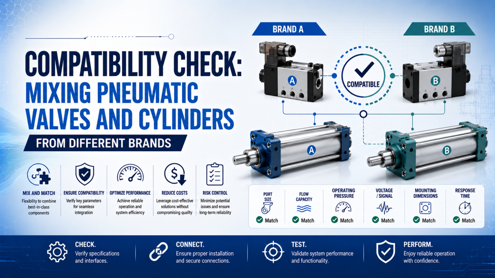
You can mix pneumatic valves and cylinders from different brands when the exact valve function, pressure range, flow path, port connection, control interface, environment, and fault response meet the machine’s requirements. Brand names do not need to match. Specifications and validated behavior do.
This is a circuit-level decision, not a catalog-label comparison. A G1/4 port or a 10 bar maximum rating confirms only one detail. It does not prove that the valve will fill and exhaust the cylinder fast enough, return to the required state after power loss, or preserve a safety function.
Key Takeaways
- Approve the combination through 8 compatibility checks, not by brand or port size alone.
- Match valve function and fault state before comparing flow.
- Size the complete supply and exhaust path for the required stroke time.
- Treat safety-related substitutions as controlled machine changes.
Can You Mix Pneumatic Valves and Cylinders from Different Brands?
ISO 4414:2010 covers the design, construction, modification, installation, operation, and maintenance of pneumatic systems and their components. It does not require one-brand systems. A mixed-brand valve and cylinder can therefore be acceptable when the completed circuit satisfies the intended function, documented limits, and machine safety requirements (ISO 4414, 2010).
The valve and cylinder do not have a proprietary relationship in an ordinary pneumatic circuit. The valve routes compressed air. The cylinder converts the resulting pressure difference into motion. What matters is whether their interfaces and operating behavior agree at the required load and speed.
That answer has boundaries. A successful bench stroke at no load does not prove production compatibility. Long tubing, a restrictive fitting, a small exhaust silencer, a helping load, or a different de-energized valve state can change the result after installation.
Use three distinct terms:
- Connection compatibility: The ports, fittings, tubing, and seals can be assembled correctly.
- Functional compatibility: The valve produces the required cylinder motion in every commanded and uncommanded state.
- Approved application: The installed combination passes documented acceptance checks for one defined machine position.
For the broader evidence behind replacement-part approval, use the separate guide to compatible pneumatic parts. This article stays narrower: it verifies the relationship between a directional valve, the air path, and a pneumatic cylinder.
A useful compatibility statement names both the evidence and the remaining limit: “The valve function, working pressure, ports, and calculated flow match; final approval depends on the loaded stroke-time and fault-state tests.” That is more defensible than either “same brand only” or “all pneumatic parts are universal.”
Eight Compatibility Checks Before You Connect Anything
ISO 15552:2018 covers detachable-mount cylinders with 32 mm to 320 mm bores and a maximum rated pressure of 1,000 kPa, or 10 bar. Its limited scope shows why one standard cannot approve an entire valve-cylinder circuit: dimensional interchangeability is only one of eight required checks (ISO 15552, 2018).
| Check | Compare | Evidence | Common hidden mismatch |
|---|---|---|---|
| 1. Valve function | 3/2, 5/2, 5/3, normal state, center condition | Valve symbol and machine circuit | Same port count, different power-loss behavior |
| 2. Pressure | Minimum, normal, maximum, pilot and proof limits | Datasheets and measured dynamic pressure | Maximum ratings overlap, but pilot pressure is too low |
| 3. Flow and timing | Required flow, valve rating, pressure drop, exhaust capacity | Supplier curves, calculation and loaded stroke test | Supply looks adequate while exhaust is restricted |
| 4. Ports and seals | Thread standard, size, gender, seal location and torque | Dimensioned drawings and gauges | NPT forced into a BSPP port |
| 5. Tubing and fittings | Tube ID, length, fittings, flow controls and silencers | Installed air-path record | Valve is large enough, but the tube or elbow is not |
| 6. Electrical control | Coil voltage, power, connector, pinout and suppression | Electrical datasheet and PLC output data | Voltage matches, but current or polarity does not |
| 7. Sensors and automation | Sensor type, output, IODD, process data and logic | Sensor files, I/O list and program review | Pneumatic motion works, but end-state proof is lost |
| 8. Application and safety | Load, speed, cushioning, environment, fault state and release test | Risk assessment and acceptance plan | Normal cycles pass, but air-loss behavior changes |
Do not make every item a pass/fail judgment from the same document. Supplier data establishes component limits. The circuit drawing defines intended behavior. Calculations screen pressure and flow. Measurements confirm what the installed machine actually does.
Mounting belongs in the review when the cylinder itself is being replaced, but it is not a direct valve-to-cylinder interface. Check bore, stroke, mounting, load, guiding, cushioning, and sensors against the machine drawing separately from the pneumatic connection.
How Do You Match Valve Function to Cylinder Action?
ISO 5599-1:2001 defines mounting interface surfaces for five-port directional valves and was confirmed current in 2024. A standard mounting surface does not establish the valve’s functional behavior. You must still match every spool position, normal state, pilot arrangement, and exhaust path to the cylinder circuit (ISO 5599-1, 2001).
Start with the actuator type:
| Cylinder requirement | Common valve starting point | Items that still require confirmation |
|---|---|---|
| Single-acting, spring return | 3/2 | Normally open or closed, exhaust path, minimum pressure |
| Double-acting, two end positions | 5/2 | Monostable or bistable, pilot source, power-loss state |
| Double-acting with defined center behavior | 5/3 | Closed, exhausted, or pressurized center; leakage and load behavior |
| Variable electronic pressure or flow | Proportional valve | Command range, response, deadband, feedback and tuning |
A 5/2 spring-return valve and a 5/2 double-solenoid valve can connect to the same cylinder ports but behave differently when electrical power disappears. The spring-return version moves to its defined normal position. A bistable version may remain in its last position. That difference can change motion, trapped pressure, and restart behavior.
For a 5/3 valve, write the center condition into the review. “All ports blocked” does not guarantee rigid position holding because compressed air, spool leakage, cylinder leakage, and external load can still move the piston. A center-exhaust valve creates a different failure state, and a pressurized-center valve creates another.
Confirm these details before sizing:
- Which valve port connects to each cylinder chamber?
- What flow path exists in every spool position?
- What happens when power is removed?
- What happens when supply or pilot pressure is lost?
- Is the valve direct acting, internally piloted, or externally piloted?
- Can pressure be trapped, and how is it released for maintenance?
The dedicated 4-way 5-port valve guide explains P, A, B, EA, and EB routing in more detail. Use the actual circuit symbol rather than assuming that two suppliers use identical port numbering.
How Do Pressure, Flow, and Exhaust Capacity Affect Compatibility?
SMC states that cylinder force depends on pressure while cylinder speed depends on airflow, and gives for a stated imperial-unit relationship. SMC also warns that port and tubing sizes affect speed. A pressure-rating match therefore cannot prove that a mixed-brand combination will meet its cycle time (SMC, accessed 2026).
Record four pressure values:
- plant supply pressure at the branch;
- regulated static pressure near the valve;
- dynamic pressure at the valve and cylinder during motion;
- maximum foreseeable pressure under normal and fault conditions.
Compare these values with the cylinder working range, the valve working and pilot ranges, every fitting and tube rating, and the settings of protective devices. A valve rated to 10 bar does not deliver 10 bar by itself. Its outlet pressure is created by the supply, regulation, circuit state, flow demand, and downstream load.
Estimate the flow before comparing valve ratings
For a first-pass extension estimate, calculate swept volume from piston area and stroke:
Here, is effective piston area, is bore, is stroke, is target one-way stroke time, is approximate absolute chamber pressure during motion, and is the absolute reference pressure used for normalized flow. Keep units consistent.
This is a screening estimate, not a final valve rating. For a rod-type cylinder, use the annular area on the rod side when estimating retract demand. Add dead volume, leakage, cushion behavior, acceleration, pressure loss, and an application-specific margin where relevant. Then compare the result with manufacturer flow data under compatible test conditions.
ISO 6358-1:2013 specifies steady-state tests for pneumatic components using compressible fluids, and its 2026 Amendment 2 addresses measurement uncertainty. Cv, Kv, sonic conductance , critical pressure ratio , and nominal flow cannot be compared reliably unless their reference conditions and pressure points are understood (ISO 6358-1, 2013; Amendment 2, 2026).
Check the complete path in both directions:
FRL → supply tube → valve inlet → valve working port → fitting → cylinder port → opposite chamber → flow control → valve exhaust → silencer
The smallest effective restriction can control the stroke. Measure pressure during the loaded move, not only while the machine is idle. If one direction is slow, compare the two exhaust paths, flow-control orientation, cushion settings, and silencers before replacing the valve.
An oversized valve does not automatically increase the cylinder’s air consumption per stroke. It can increase cost, internal volume, switching disturbance, and control sensitivity, while oversized tubing between the valve and cylinder adds dead volume. Choose the smallest path that meets the required motion with acceptable pressure loss and adjustment range.
For valve-type selection rather than brand compatibility, see the guide to pneumatic flow-control valve types.
For the longer calculation sequence, use the companion guide to pneumatic flow rate and valve pre-selection. Keep its calculated requirement separate from the final loaded-machine measurement.
How Do You Verify Port Threads and Sealing?
ISO 228-1:2000 covers parallel pipe threads from 1/16 to 6 inches where pressure-tight joints are not made on the threads. It requires sealing through external mating surfaces when a pressure-tight joint is needed. This makes the seal location as important as nominal port size during a compatibility check (ISO 228-1, 2000).
| Port designation | Thread behavior | Normal sealing principle | Standard to verify |
|---|---|---|---|
| NPT | Tapered inch thread | Thread interference plus approved sealant | ASME B1.20.1 |
| R or Rc, commonly called BSPT | Tapered or mating pipe thread | Pressure-tight joint on the thread | ISO 7-1 |
| G, commonly called BSPP | Parallel thread | Washer, bonded seal, O-ring, or defined sealing face | ISO 228-1 |
| Metric port | Usually parallel | Product-specific O-ring or sealing face | Exact supplier drawing |
ASME B1.20.1 covers dimensions and gauging for NPT and related general-purpose inch pipe threads. ISO 7-1 covers pipe threads where pressure-tight joints are made on the threads. Similar pitch and diameter do not make NPT, BSPT, and BSPP interchangeable (ASME B1.20.1; ISO 7-1).
Use this verification sequence:
- Read the complete port designation from the current drawing or part code.
- Measure major diameter and pitch or threads per inch.
- Determine whether the thread is parallel or tapered.
- Check thread form and the specified gauge standard.
- Identify where the joint is designed to seal.
- Verify fitting engagement, torque, material, pressure, temperature, and media.
- Check installed clearance and tube loading.
A thread-pitch gauge is useful, but it cannot identify every port by itself. Confirm the result against a dimensioned manufacturer drawing or the correct limit gauge. Do not force a fitting because it starts by hand.
An adapter can create a valid engineered connection when its thread standards, seal faces, flow area, pressure rating, materials, installed length, and service access are acceptable. Record it in the bill of materials and drawing. The connection is then an approved adapted interface, not a direct interchange.
The pneumatic port-thread guide covers thread and sealing details beyond this circuit checklist.
What Must Match on the Electrical and Sensor Side?
The IO-Link system description assigns each device an IODD containing communication properties, parameters, identification, process data, and diagnostic information. A pneumatic port can remain compatible while automation data does not. The valve, cylinder sensor, master port, device identity, and PLC logic must therefore be checked as separate interfaces (IO-Link System Description, 2018).
A conventional pneumatic cylinder normally has no communication protocol. Its reed or solid-state position sensors connect to the control system separately. A smart valve manifold may provide IO-Link or fieldbus diagnostics, but changing the cylinder alone does not automatically remove those valve diagnostics.
Check valve actuation data:
- rated voltage and permissible range;
- AC frequency where applicable;
- continuous and pickup power;
- duty cycle and temperature limits;
- connector, pinout, polarity and protective earth;
- indicator and surge-suppression circuit;
- PLC output current, group current and diagnostic pulses;
- fieldbus node, station configuration and process-data mapping.
Check cylinder sensing data:
- whether the piston has the required magnet;
- sensor groove and mounting hardware;
- reed, PNP, NPN, two-wire, or other output type;
- supply voltage, load current and leakage current;
- cable or connector;
- sensing position, hysteresis and controller logic.
For IO-Link devices, compare the required specification version, IODD, VendorID, DeviceID, process-data layout, parameters, diagnostics, and replacement procedure. The official IO-Link quality policy treats VendorID, DeviceID, and IODD as prerequisites for device identification and parameterization (IO-Link Product Quality Policy, 2025).
Separate “motion compatibility” from “information compatibility.” The cylinder may extend and retract correctly while the controller loses end-position proof, diagnostic bits, parameter restore, or alarm meaning. Both layers must pass before the machine can be released.
When Does Mixing Brands Become a Safety-Related Change?
ISO 13849-1:2023 applies to safety-related control systems using electrical, hydraulic, pneumatic, and mechanical technologies. It does not assign the required performance level for a particular machine. When a valve contributes to a safety function, cross-brand substitution must preserve the validated architecture, behavior, diagnostics, and component assumptions (ISO 13849-1, 2023).
Treat the change as safety-related when the valve or cylinder affects:
- prevention of unexpected movement;
- safe exhaust or pressure isolation;
- load holding or controlled pressure retention;
- redundant shut-off and monitoring;
- safe speed, force, position, or stopping;
- guard-locking or clamp-state confirmation;
- restart prevention after power or air returns.
Do not infer safe behavior from a normal production cycle. Test the defined safety function under the conditions in its validation plan, including loss and restoration of electrical power, loss and restoration of air, a stuck or leaking valve where applicable, sensor faults, residual pressure, and restart.
A higher component rating or a standard mounting interface does not preserve diagnostic coverage, category, or performance level. If the original validation depends on manufacturer reliability data, monitoring logic, a certified subsystem, or a defined exhaust arrangement, verify whether the proposed combination keeps those assumptions valid.
ISO 4414 also applies to pneumatic-system modification and addresses significant hazards associated with intended use. Update the circuit diagram, risk assessment, validation record, maintenance isolation procedure, spare-parts list, and training when the approved configuration changes.
A Controlled Compatibility Test and Release Plan
ISO 10099:2001 is a four-page standard for final functional examination of double-acting, single-rod pneumatic cylinders and was confirmed current in 2023. Its limited component scope reinforces the release principle: documented cylinder checks do not replace an application trial with the real load, pressure, tubing, exhaust path, and controls (ISO 10099, 2001).
Use four release gates:
- Document review: Record the complete valve and cylinder part codes, drawings, symbols, pressure and temperature limits, flow data, seal materials, sensors, coil data, and declared standards.
- Engineering comparison: Complete the eight-check matrix. Mark each requirement as matched, adapted with an approved change, pending test, or incompatible.
- First article: Inspect the received configuration, gauge the relevant ports, verify wiring and valve state, perform an approved leak check, and confirm adjustment access.
- Guarded machine trial: Run the loaded application through normal production, maximum intended demand, simultaneous demand where applicable, fault states, and restart.
Define pass limits before the trial:
| Result | Measurement | Example acceptance basis |
|---|---|---|
| Motion | Extend and retract time under load | Machine cycle requirement |
| Pressure | Dynamic pressure at valve and cylinder | Minimum force and supplier limits |
| End behavior | Impact, rebound and cushion adjustment | Cylinder data and machine limit |
| Leakage | External and permitted internal leakage | Supplier specification and site procedure |
| Sensing | End-state signal and timing | PLC sequence requirement |
| Fault response | Motion, exhaust, trapped pressure and restart | Risk assessment and validation plan |
| Environment | Temperature, washdown, corrosion and media | Exact configured component ratings |
Use calibrated instruments and record the test conditions. A result such as “ran without problems” cannot be compared later. Keep pressure, load, speed setting, tube details, firmware or program revision, instrument identity, measured value, acceptance limit, and disposition.
Approve one exact configuration for one defined application or application family. Preserve the accepted part codes, adapters, drawings, settings, software mapping, test record, and revalidation triggers. Require review when a supplier changes the seal package, spool, coil, connector, flow rating, sensor, firmware, or manufacturing revision.
When the proposed change is a valve replacement rather than a new circuit pairing, the OEM solenoid-valve compatibility checklist provides the electrical, coil, manifold, and first-article details required for that narrower task.
The final decision should be one of three outcomes:
- Compatible as configured: All interfaces and tests pass without an uncontrolled change.
- Compatible with controlled changes: An adapter, wiring change, parameter update, or revised procedure is documented and approved.
- Not compatible: At least one required function, rating, interface, environmental limit, or safety condition cannot be demonstrated.
Mixed-Brand Pneumatic Valve and Cylinder FAQs
ISO 6358-1 defines flow testing for pneumatic components, while ISO 5599-1 defines selected five-port valve mounting interfaces. Neither standard approves a complete machine application. These FAQs address the practical decisions that remain after standard designations, nominal pressure, and port size have been compared (ISO 6358-1; ISO 5599-1).
Can I connect a rodless cylinder to a valve from another manufacturer?
Yes, if the valve function, pressure range, required supply and exhaust flow, port connection, tubing, control state, and application limits match. Rodless construction does not create a special brand protocol. Long strokes and external carriage loads can, however, make pressure loss, exhaust restriction, cushioning, and dynamic testing more important.
Is matching port size and working pressure enough?
No. A G1/4 port and overlapping maximum pressure confirm only two attributes. Check spool function, minimum pilot pressure, flow data under stated conditions, tube ID and length, exhaust restriction, sensor logic, environmental limits, power-loss behavior, and the loaded stroke result before approving the combination.
Does a valve with a higher maximum pressure rating protect the cylinder?
No. A rating states what the valve may withstand or operate within under defined conditions; it does not regulate the downstream circuit. Protect the cylinder by controlling the maximum foreseeable supply pressure with correctly selected regulation and protective devices, then verify the actual static and dynamic pressure at the application.
Can I use an adapter between NPT and BSPP ports?
Yes, when the adapter provides the correct NPT and BSPP interfaces, sealing methods, pressure and temperature ratings, materials, flow area, engagement, clearance, and installation torque. Document the adapter as part of the approved configuration. Never force unlike threads together or rely on extra sealant to correct an interface mismatch.
Will mixing brands void the warranty?
There is no universal answer. Review the machine contract and each component warranty for the exact application, jurisdiction, modification, and cause-of-failure terms. Keep compatibility calculations, drawings, supplier data, first-article results, and approval records. Technical compatibility and contractual warranty coverage are separate decisions.
Sources and Technical References
- ISO 4414:2010, Pneumatic fluid power: General rules and safety requirements
- ISO 6358-1:2013, steady-state flow-rate test methods
- ISO 6358-1:2013/Amd 2:2026, evaluation of measurement uncertainty
- ISO 15552:2018, detachable-mount cylinder dimensions
- ISO 5599-1:2001, five-port directional-valve mounting interfaces
- ISO 10099:2001, cylinder final examination and acceptance criteria
- ISO 7-1, pressure-tight pipe threads
- ISO 228-1:2000, parallel fastening pipe threads
- ISO 13849-1:2023, safety-related parts of control systems
- ASME B1.20.1, general-purpose inch pipe threads
- SMC, Control Air Flow of Cylinders
- IO-Link System Description
- IO-Link Product Quality Policy