

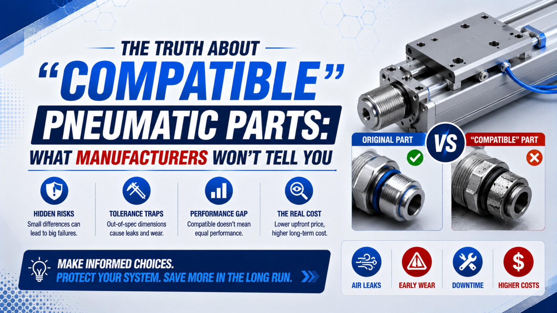
A pneumatic part is compatible only when the exact offered configuration fits the machine, connects to the existing air and control interfaces, performs the required duty, and passes the site’s release criteria. A shared standard, bore, port label, protocol, or product description can support one part of that decision. None proves the entire replacement.
What do product pages often leave unresolved? They may identify the family and its maximum ratings while omitting the option-specific drawing, rod end, port variant, cushion, sensor, seal package, environmental limits, change status, or test conditions. The buyer must join those details to the installed machine.
Key Takeaways
- ISO 15552 standardizes selected cylinder dimensions, not complete performance.
- ISO 21287 covers compact single-rod cylinders, not rodless cylinders.
- Treat warranty, support, safety, and engineering compatibility as separate decisions.
- Release a substitute only after drawing review, functional checks, a controlled machine trial, and revision control.
Dimensional interchangeability is the ability to install a part through the interfaces controlled by a named standard or drawing. Functional equivalence is the ability of the exact configured part to meet the machine’s force, timing, sensing, environmental, and safety requirements. Approved replacement means both claims have been demonstrated and recorded for one defined application.
This guide covers the evidence behind a compatibility claim. The separate ISO 15552 interchangeability checklist handles that cylinder family in detail, while the OEM versus aftermarket TCO review covers the later cost decision.
What Does “Compatible” Actually Promise?
ISO 15552:2018 covers detachable-mount pneumatic cylinders with 32–320 mm bores and a maximum rated pressure of 1,000 kPa. Its scope establishes basic, mounting, and accessory dimensions required for interchangeability; it does not declare every cylinder in that dimensional family functionally identical (ISO 15552:2018, confirmed 2025).
The word “compatible” needs an object and a test. Compatible with what machine position? Under which pressure, load, speed, temperature, media, contamination level, control voltage, protocol, and safety function? A statement without those boundaries is a candidate-selection claim, not an engineering release.
Use four evidence layers:
- Standardized fit: The named standard controls the relevant mounting or connection features.
- Configured interfaces: The complete order code provides the required ports, rod end, sensor provision, cushion, connector, materials, and accessories.
- Functional duty: The exact part meets pressure, flow, force, motion, leakage, environment, life, and maintenance requirements.
- Validated release: The received item passes first-article inspection and the machine’s acceptance test, then remains under change control.
The most useful response to “Is it compatible?” is not yes or no. It is a boundary statement: “These named interfaces match; these performance items still require verification; these application tests control final release.” That language prevents a catalog similarity from becoming an undocumented machine change.
Standards Define Boundaries, Not Complete Substitutes
ISO 21287:2004 establishes a 20–100 mm metric series of single-rod compact cylinders for up to 1,000 kPa. The standard explicitly says this series lacks adjustable cushioning and is restricted to systems that do not require it. It is not a rodless-cylinder standard (ISO 21287:2004, confirmed 2023).
Every standard has a title and scope. Those two items determine what a conformity claim can support:
| Reference | What it controls | Important boundary |
|---|---|---|
| ISO 15552:2018 | Basic, detachable-mount, and accessory dimensions for specified pneumatic cylinders | Does not standardize every option or functional characteristic |
| ISO 21287:2004 | Dimensions for specified single-rod compact cylinders | Not rodless; no adjustable cushioning in the defined series |
| ISO 5599-1:2001 | Mounting interface surfaces for five-port directional valves without an electrical connector | An interface match does not establish valve flow, response, seal, or coil equivalence |
| ISO 5599-2:2001 | Related valve mounting surfaces with an optional electrical connector | The complete electrical and pneumatic configuration still matters |
| ISO 15218:2003 | Four sizes of mounting interface for specified 3/2 solenoid valves | Does not turn all 3/2 valves into functional substitutes |
| ISO 10099:2001 | Final functional examination and acceptance criteria for specified double-acting, single-rod cylinders | Does not define the machine’s application-specific acceptance limits |
ISO does not certify products or issue certificates. Its conformity guidance distinguishes supplier declarations, customer assessment, and third-party activity as different evidence routes (ISO Certification; ISO CASCO conformity attestations, accessed July 26, 2026). Therefore, ask who made the conformity statement, for which exact product and revision, against which clauses, and with what supporting evidence.
For North American square-head cylinders, don’t substitute an ISO metric family by converting bore and stroke values. Use the separate NFPA interchangeable-cylinder guide to identify the governing mounting family and configured drawing.
Which Configuration Details Must Match?
ISO 15552 allows single-rod or double-rod cylinders, with or without provisions for magnetic sensors, inside one dimensional family. Those alternatives show why a family-level label cannot identify the ordered product. The complete part code and option-specific drawing must control the comparison (ISO 15552:2018, confirmed 2025).
Start with the incumbent identification plate and the latest machine drawing. Photograph the installed cylinder, valve, fitting, sensor, or manifold before removal. Record orientation, cable routing, tubing, brackets, adjustment access, connector keying, and nearby obstructions. Then compare the exact offered configuration, not a generic catalog picture.
For cylinders, verify:
- bore, usable stroke, retracted length, extended envelope, and permitted overtravel;
- mounting style, hole pattern, centerline, locating features, and accessories;
- rod diameter, rod-end thread, gender, usable engagement, and mating hardware;
- port designation, size, location, thread form, sealing method, and fitting clearance;
- cushioning type, adjustment access, moving mass, speed, and residual impact;
- piston magnet, sensor type, switching position, cable or connector, and controller input;
- pressure, temperature, speed, side load, corrosion, washdown, cleanroom, and lubrication limits.
For valves and manifolds, compare the full pneumatic function as well as the base:
- port map and spool function;
- normal and energized states;
- center condition for three-position valves;
- pilot supply and exhaust arrangement;
- rated flow under stated test conditions;
- operating pressure, response, leakage, and media;
- coil voltage, power, duty, suppression, connector, manual override, and fieldbus node.
For fittings, seals, sensors, and accessories, a shared nominal size still leaves important questions:
| Component | Label that can mislead | Additional evidence required |
|---|---|---|
| Fitting | G1/4 or 1/4 NPT | Thread standard, seal location, engagement, tube OD, pressure, material and media |
| O-ring or seal | Same nominal size | Compound, hardness, lubricant, finish, squeeze, motion, temperature and media |
| Cylinder sensor | Fits the same groove | Magnetic target, voltage, output type, connector, sensing zone and controller logic |
| Silencer or flow control | Same thread | Effective flow area, adjustment direction, exhaust back pressure and contamination tolerance |
| Shock absorber | Same mounting thread | Effective mass, impact velocity, stroke, energy per cycle, temperature and duty |
The pneumatic port-thread guide explains why similar-looking parallel and tapered threads cannot be approved by nominal size alone. If force is an acceptance variable, use the cylinder force guide to define the calculation and then measure pressure during motion.
When Is a Manufacturer Warning Technically Justified?
ISO 13849-1:2023 gives a methodology for safety-related control systems across electrical, hydraulic, pneumatic, and mechanical technologies, but it does not prescribe the safety function or required performance level for a particular machine. A cross-brand substitution must preserve the validated safety function; matching logos or dimensions is irrelevant (ISO 13849-1:2023).
A manufacturer warning can fall into four different categories:
- Technical incompatibility. A dimension, function, rating, material, protocol, or option does not meet the stated requirement. Ask for the exact specification and test condition.
- Support boundary. The supplier will not troubleshoot a mixed system or accept responsibility for another company’s component. That is a service position, not proof that the system cannot operate.
- Contract or warranty condition. The written warranty or machine contract restricts parts, service, or modifications. Review the actual document and applicable law instead of assuming a universal rule.
- Unsubstantiated statement. The warning names no conflicting requirement or evidence. Request a written technical explanation before accepting or rejecting it.
The Magnuson-Moss Warranty Act should not be used as a blanket answer for industrial equipment. FTC guidance says the Act applies to written warranties on consumer products and does not apply to products sold for resale or commercial purposes (FTC Businessperson’s Guide to Federal Warranty Law, accessed July 26, 2026). Industrial warranty effects depend on the contract, transaction, jurisdiction, modification, and cause of failure.
CE marking is also not an interchangeability certificate. The European Commission states that it is a manufacturer’s declaration against applicable EU requirements and does not indicate that the product was approved as safe by the EU or another authority (European Commission CE marking guidance, accessed July 26, 2026). A machine modification may require the responsible economic operator to reassess the technical file and declaration.
Do not ask whether a warning is “true” in the abstract. Ask which requirement owner issued it. A supplier owns its product ratings and support terms. The machine builder owns its design specification. The employer or integrator owns the installed risk assessment and acceptance. The contract and jurisdiction determine warranty consequences.
How Do You Prove Functional Equivalence?
ISO 10099:2001 specifies final functional tests and acceptance criteria for double-acting, single-rod pneumatic cylinders. Its narrow scope demonstrates the correct principle: functional acceptance requires defined tests, but the machine still needs application-specific criteria for load, timing, impact, sensing, environment, and safety (ISO 10099:2001, confirmed 2023).
Turn every compatibility claim into a measurable requirement:
| Requirement | Evidence before purchase | First-article check | Machine acceptance |
|---|---|---|---|
| Fit | Controlled drawing and CAD comparison | Critical dimensions and mating interfaces | Installs without forcing, binding, or unapproved modification |
| Pressure and media | Rated range, materials and supplier conditions | Identification and leak check | Stable operation at measured dynamic pressure |
| Force or torque | Bore, rod, pressure and rating data | Configuration verification | Required motion under worst credible load |
| Flow and timing | Valve flow data, tube and port details | Correct function and adjustment range | Loaded stroke or response time within limits |
| Stopping | Cushion or shock-absorber data | Correct option and adjustment | Residual impact and rebound within the machine limit |
| Sensing and controls | Electrical diagram, protocol and I/O data | Wiring, output type and switching check | Correct state detection through the full operating sequence |
| Environment | Temperature, corrosion, ingress, cleanroom and media data | Materials and option identification | Trial at defined operating conditions |
| Safety | Risk assessment and safety-function design | Exact safety-related configuration | Validation of the affected safety function |
| Service | Parts list, instructions, tools and support route | Maintenance access | Approved spare, inspection and replacement procedure |
Testing a no-load stroke is not proof of equivalence. It can miss guide moments, exhaust restriction, cushion energy, sensor timing, thermal behavior, or failure during loss of pressure. Define credible boundary conditions before the trial and keep personnel behind the required guarding.
What about IO-Link? A common protocol supports interoperability only when the master, device, profile, IODD, VendorID, DeviceID, ports, process data, parameterization, and application logic align. The IO-Link product-quality policy treats conformity and interoperability as controlled test objectives, not assumptions created by the logo (IO-Link Product Quality Policy, 2023).
For valves, the separate Cv sizing guide explains why a flow coefficient must be tied to pressure conditions and required flow. Piston displacement per minute is not a direct Cv calculation.
How Should a Cross-Brand Replacement Be Released?
ISO conformity assessment recognizes three evidence relationships: first-party supplier declaration, second-party customer assessment, and third-party independent activity. A practical replacement release adds a fourth layer, the installed machine trial, because conformity to a product standard does not prove performance in one specific application (ISO CASCO conformity attestations).
Use four release gates:
- Candidate evidence: Obtain the complete part code, current drawing, specification, declared standards, materials, ratings, warranty terms, support route, manufacturing revision, and change-notification terms.
- Engineering comparison: Map each machine requirement to the standard, supplier drawing, calculation, or application test that controls it. Record every difference and required adapter.
- First article and guarded trial: Inspect the received configuration, verify critical dimensions and function, then run the machine acceptance plan under controlled conditions.
- Controlled approval: Assign the approved supplier part number to one machine position or defined application family. Retain the evidence, limits, approvers, golden sample if useful, and revalidation triggers.
Start with a low-consequence position only when the same evidence can later support the intended application. A successful trial on an unloaded maintenance fixture cannot approve a production axis with different mass, speed, environment, or safety consequences.
For sourcing identity and storage history, use the separate gray-market pneumatic component guide. Provenance answers where the part came from; compatibility answers whether the exact part is acceptable for the machine.
Documenting Approval and Change Control
ISO/IAF external-provider guidance identifies four procurement controls: current approved-provider information, orders placed against defined criteria, supplier performance monitoring, and activities that confirm requirements were met. It also says approved-provider lists alone may be insufficient for critical components (ISO 9001 Auditing Practices Group, External Providers, 2016).
The approved record should include:
- machine, location, assembly and function;
- incumbent and replacement manufacturer part numbers;
- standard and revision claimed;
- complete order-code interpretation;
- drawing comparison and critical-characteristic results;
- calculations and assumptions used;
- first-article inspection;
- machine test conditions, results and acceptance limits;
- safety, regulatory, contract and warranty reviews where applicable;
- deviations, adapters and updated maintenance instructions;
- approvers and approval date;
- supplier drawing, material, firmware, manufacturing-site and part-number changes that trigger revalidation.
“Approved alternate” is too broad when it has no application boundary. An alternative can be approved for one machine position, pressure range, temperature, load, software revision, or non-safety function without being approved everywhere the incumbent part appears. Store that scope with the part cross-reference.
Monitor field performance after release. Record installation date, failure mode, returned-part findings, adjustment range, leakage, service time, and any supplier corrective action. A replacement that passes commissioning but causes repeated cushion adjustment or sensor drift is not equivalent in maintenance terms.
The truth about compatible pneumatic parts is neither “OEM only” nor “standards make brands irrelevant.” Standards reduce uncertainty in named interfaces. Configuration data, engineering review, and machine testing resolve the rest. Demand evidence from every supplier, including the incumbent.
Siyu Wang prepared this application-focused guide for Bepto Pneumatic. Technical and legal-boundary claims were checked against the standards, regulator, and industry sources listed below. For an application review, use the contact page and provide both part codes, drawings, operating conditions, machine function, and acceptance criteria.
Compatible Pneumatic Parts FAQs
ISO 15552 covers 32–320 mm detachable-mount cylinders, while ISO 21287 covers 20–100 mm compact single-rod cylinders without adjustable cushioning. These two ranges alone show why “ISO compatible” is incomplete without the standard number, product scope, configuration, and application evidence (ISO 15552; ISO 21287).
Does ISO 15552 compliance make two cylinders fully interchangeable?
No. ISO 15552 establishes specified basic, mounting, and accessory dimensions for its cylinder family. The configured port, rod end, sensor provision, cushion, materials, pressure, speed, environment, and installed performance still require comparison. Treat the ISO label as dimensional evidence, then complete functional and machine-acceptance checks.
Is ISO 21287 a standard for rodless cylinders?
No. ISO 21287 covers a metric series of single-rod compact pneumatic cylinders with 20–100 mm bores and a maximum working pressure of 1,000 kPa. The defined series has no adjustable cushioning. A rodless-cylinder replacement needs its own supplier drawings, load and moment ratings, carriage interfaces, sealing system, and acceptance test.
Can a manufacturer automatically void an industrial machine warranty for using another brand?
There is no universal answer. Industrial warranty consequences depend on the written contract, transaction, jurisdiction, modification, and cause of failure. The U.S. Magnuson-Moss Act concerns consumer-product warranties and generally does not cover products sold for commercial purposes. Obtain written, application-specific guidance before changing a warranted machine.
Does CE marking prove that a replacement pneumatic part is safe and compatible?
No. The European Commission describes CE marking as the manufacturer’s declaration that the product meets applicable EU requirements. It is not an EU safety approval and does not prove interchangeability. The responsible machine manufacturer or integrator must still assess the modification, technical file, affected safety functions, interfaces, and required declaration.
What is the minimum evidence for approving a compatible pneumatic replacement?
Use four gates: exact candidate documents, an engineering comparison, first-article inspection with a controlled machine trial, and a scoped approval under change control. Record the machine position, configuration, test conditions, limits, deviations, approvers, and revalidation triggers. A seller cross-reference or successful no-load stroke is not enough.
Sources and technical references
- ISO 15552:2018. Basic, mounting, and accessory dimensions for specified detachable-mount pneumatic cylinders, 32–320 mm bore and up to 1,000 kPa. Confirmed current in 2025. https://www.iso.org/standard/66921.html
- ISO 21287:2004. Single-rod compact pneumatic cylinders, 20–100 mm bore, up to 1,000 kPa, without adjustable cushioning. Confirmed current in 2023. https://www.iso.org/standard/34465.html
- ISO 10099:2001. Final functional examination and acceptance criteria for specified double-acting, single-rod pneumatic cylinders. Confirmed current in 2023. https://www.iso.org/standard/30054.html
- ISO 13849-1:2023. Methodology for designing and integrating safety-related control-system parts across multiple technologies. https://www.iso.org/standard/73481.html
- ISO 5599-1:2001. Five-port directional-valve mounting interface surfaces without an electrical connector. Confirmed current in 2024. https://www.iso.org/standard/33074.html
- ISO 15218:2003. Mounting interface surfaces for specified 3/2 solenoid valves. Confirmed current in 2023. https://www.iso.org/standard/26927.html
- ISO Certification. Explains that ISO develops standards but does not perform certification or issue certificates. Accessed July 26, 2026. https://www.iso.org/certification.html
- ISO CASCO conformity attestations. Distinguishes supplier declarations and other conformity-assessment routes. Accessed July 26, 2026. https://casco.iso.org/attestations-of-conformity.html
- FTC Businessperson’s Guide to Federal Warranty Law. Defines the consumer-product scope and commercial-purpose exclusion of Magnuson-Moss. Accessed July 26, 2026. https://www.ftc.gov/business-guidance/resources/businesspersons-guide-federal-warranty-law
- European Commission CE marking guidance. Defines CE marking as the manufacturer’s declaration and explains that it is not an EU safety approval. Accessed July 26, 2026. https://single-market-economy.ec.europa.eu/single-market/goods/ce-marking_en
- ISO 9001 Auditing Practices Group, External Providers. Risk-based purchasing, supplier, monitoring, and verification guidance. Published 2016. https://committee.iso.org/files/live/sites/tc176/files/documents/ISO%209001%20Auditing%20Practices%20Group%20docs/Auditing%20to%20ISO%209001%202015/APG-ExternalProviders2015.pdf
- IO-Link Product Quality Policy. Conformity and interoperability controls for IO-Link masters and devices. Published 2023. https://io-link.com/fileadmin/user_upload/Downloads/Test___Quality/IO-Link-Product_Quality_Policy_10132_V170_Feb26.pdf