

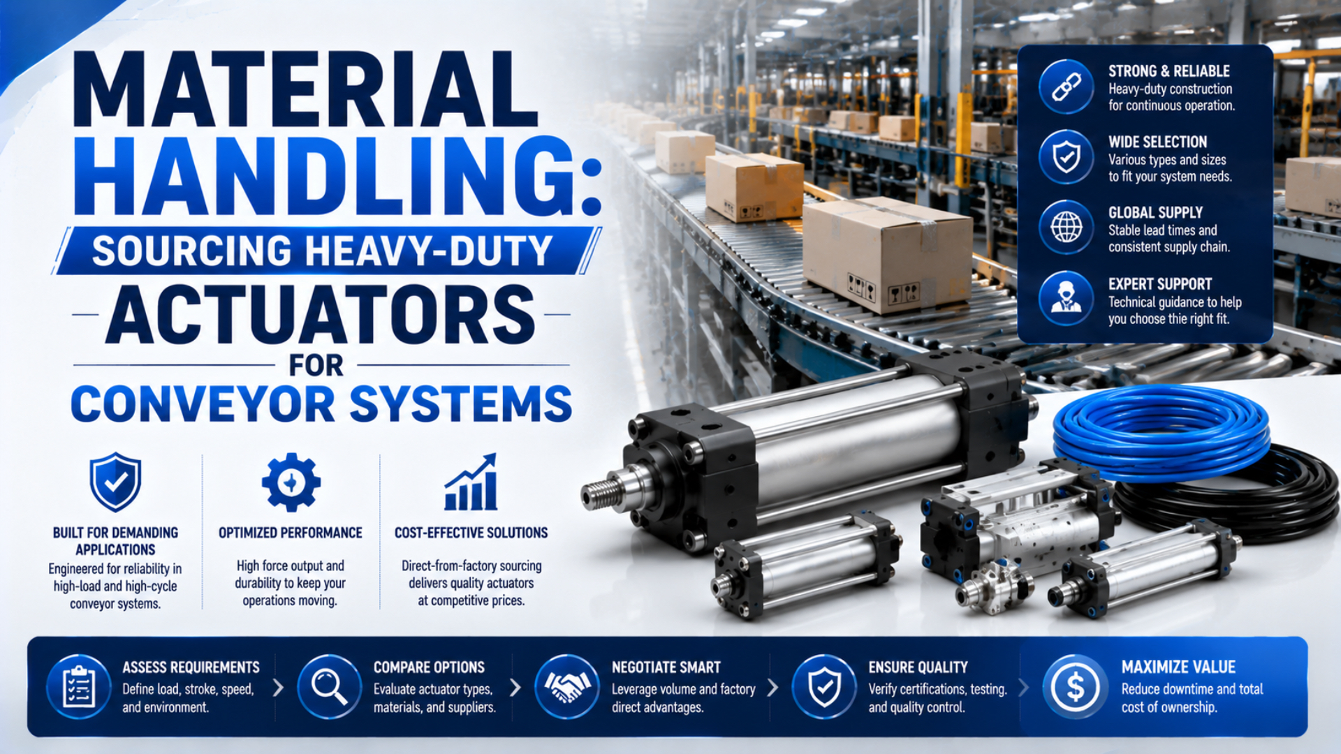
A heavy-duty actuator for a conveyor is not defined by a black finish, a larger rod, or a marketing label. It is an actuator whose documented force, load path, speed, cushioning, environment, interfaces, and duty limits cover one identified conveyor motion with an acceptable margin.
The sourcing task therefore begins at the machine, not in a cylinder catalog. A stop gate, pusher, diverter, lift, clamp, and transfer slide can all use pneumatic motion, yet each imposes a different combination of load, guidance, impact, holding, alignment, and failure consequence.
Key Takeaways
- ISO 15552 covers selected interfaces for 32 to 320 mm bores, not complete application suitability.
- Calculate force at the moving chamber, including back pressure and resistance.
- Keep conveyor side load on an external guide whenever possible.
- Buy against drawings, performance curves, materials, tests, and a controlled part number.
A heavy-duty conveyor actuator application envelope is the controlled definition of what must move, how fast, through what stroke, under which forces and environment, with which interfaces, and with what proof. Heavy-duty actuators for conveyor systems should be sourced against this envelope.
Heavy-Duty Is an Application Rating, Not a Product Label
Treat “heavy-duty” as an application conclusion, not a standardized cylinder class. ISO 15552:2018 is an 18-page dimensional standard covering detachable-mounting cylinders from 32 to 320 mm bore at up to 1,000 kPa. It establishes selected interfaces for interchangeability, but not conveyor load, life, speed, or shock performance (ISO 15552, confirmed 2025).
The phrase can describe useful construction features: a larger bearing, alternative rod material, stronger mount, external guide, replaceable wear parts, scraper, corrosion-resistant finish, or higher-capacity cushion. Yet the feature matters only when its manufacturer rating addresses the actual failure mode.
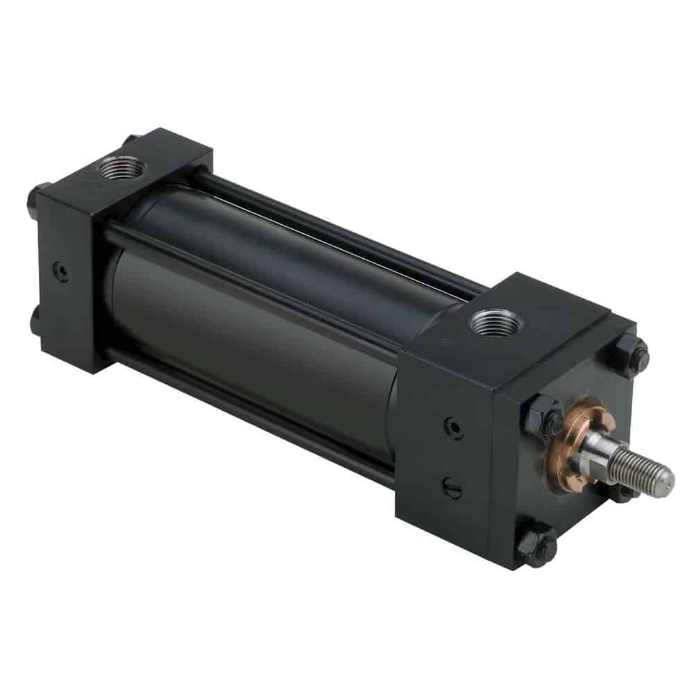
A substantial tie-rod cylinder may suit demanding service, but appearance alone does not establish force margin, side-load capacity, cushioning energy, environmental compatibility, or cycle life.
Ask suppliers to replace the label with evidence:
| Claimed feature | Evidence that makes it useful |
|---|---|
| Heavy-duty rod | Rod diameter, material, surface, allowable load, buckling method, and approved mounting case |
| Long bearing | Bearing material and model-specific radial-load or moment limit |
| High-cycle seals | Exact seal compound, lubricant policy, operating envelope, test conditions, and exclusion limits |
| High-speed operation | Permitted speed, valve and flow assumptions, cushion-entry speed, and kinetic-energy limit |
| Reinforced mount | Drawing, material, fastener grade, allowable force or moment, and installation torque |
| Conveyor-ready | Defined environment, sensors, cable protection, maintenance access, and acceptance checks |
No universal number of cycles separates a standard cylinder from a heavy-duty one. A catalog endurance result is meaningful only with its pressure, speed, load factor, stroke, cushioning, air quality, temperature, lubrication, alignment, and failure criterion.
The strongest procurement question is not “Is this cylinder heavy-duty?” It is “Which documented limit governs this conveyor position?” That change forces the buyer and supplier to discuss the weakest element in the complete motion, whether it is force, guidance, cushion energy, mount fatigue, seal environment, sensor exposure, or service access.
What Must Be Defined for Each Conveyor Motion?
Define 8 application inputs before selecting a product: function, load, stroke, timing, guidance, environment, interfaces, and failure response. SMC’s 19-page air-cylinder selection guide separates bore, end-of-stroke impact, lateral load or buckling, and air demand, showing why bore and stroke alone cannot describe a conveyor actuator (SMC, retrieved 2026-07-26).
Start with the motion function:
- Stop gate: intercepts product flow and may see impact before or after the cylinder reaches position.
- Diverter: changes product direction through a gate, shoe, arm, or guided transfer.
- Pusher: moves a product across a surface and may encounter variable friction or a jam.
- Lift: raises a platform or conveyor section and creates a gravity load that may need controlled holding.
- Clamp or brake: restrains an item, often making loss of pressure and stored energy part of the risk assessment.
- Transfer slide: carries a moving assembly, usually requiring an external linear guide or guided actuator.
Then complete one data sheet for each cylinder position:
| Input | Minimum information |
|---|---|
| Function | Move, stop, divert, lift, clamp, index, or transfer; normal and abnormal states |
| Load | Product mass range, moving mechanism mass, friction, incline, acceleration, impact, process force |
| Motion | Stroke, extend and retract direction, end clearance, position repeatability, dwell, timing |
| Duty | Cycles per minute, shifts, consecutive cycles, peak periods, rest periods, expected machine life |
| Guidance | Guide type, rail spacing, load center, allowed misalignment, side load, roll/pitch/yaw moments |
| Environment | Temperature, dust, washdown, chemicals, moisture, corrosion, food contact, outdoor exposure |
| Interfaces | Mount, rod end or carriage, ports, tubing, valve, sensors, connector, cable exit, envelope |
| Failure response | Safe state, trapped energy, gravity motion, jam behavior, manual recovery, maintenance access |
For safety-related behavior, describe the machine function instead of assigning it casually to the cylinder. ISO 12100:2010 provides a 77-page methodology for machinery risk assessment and risk reduction. Determine the required safe state, guarding, control performance, gravity restraint, stored-energy release, and reset behavior at machine level (ISO 12100, confirmed 2022 and under revision).
How Should Required Force and Bore Be Calculated?
Calculate the worst credible force in each direction, then compare it with force available at the cylinder chamber during motion. SMC’s 19-page guide uses different load factors for static, guided horizontal, and vertical or horizontal dynamic work, and advises reducing the factor further at high speed rather than applying one universal safety percentage (SMC).
For a load moving uphill on an incline, a useful free-body model is:
is required actuator force in newtons, is the effective moving mass in kilograms, is acceleration in metres per second squared, is the applicable friction coefficient, is gravitational acceleration, is conveyor incline, and covers an additional gate, clamp, spring, or product force. Reverse signs and directions for the actual motion case.
Available extension force is better represented as:
is cap-end pressure while moving, is opposing rod-side pressure, is bore diameter, and is an application allowance for internal resistance and dynamic uncertainty. Use pascals with square metres to obtain newtons. For retraction, subtract rod area from piston area.
Why use moving chamber pressure? Static regulator pressure can overstate the force available after valve, fitting, tubing, silencer, flow, and exhaust losses. Check the pressure trace or establish a conservative pressure at the cylinder port for the required speed.
The calculator checks cylinder output, not the complete conveyor mechanics. Build the load equation first. If the required force changes with product size, belt condition, incline, or gate position, calculate each case and select from the governing one.
In our experience, conveyor RFQs often provide package mass but omit the moving gate, link, carriage, and guide friction. That makes a neat bore calculation look more certain than it is. A marked-up mechanism drawing with force direction and load center usually resolves the missing assumptions faster than another spreadsheet revision.
For lifting, never treat pneumatic force alone as a verified holding method. Identify what occurs after loss of pressure, hose failure, valve de-energization, sensor failure, or a jam. A mechanical restraint, rod lock, counterbalance, safety circuit, or different actuator technology may be required by the machine risk assessment.
How Do Guidance, Mounting, and Side Load Change the Choice?
Keep conveyor load reactions off a standard piston rod unless the manufacturer explicitly rates the exact case. SMC’s 19-page selection guide requires lateral load to be checked against model-specific graphs and separately calls for a buckling check on relatively long strokes, so a larger rod diameter alone is not an application approval (SMC).
Side load usually enters through an offset product force, gate arm, carriage mass, misaligned rail, rigid rod connection, or mounting deflection. Map the force path from product to frame. Then calculate the reactions at the guides, bearings, pins, mounts, and cylinder connection.
Choose the mechanical arrangement deliberately:
- use a guided slide, guided cylinder, rodless carriage, or separate linear rail when the load needs support;
- use clevis, trunnion, spherical, or floating connections only where their permitted motion matches the mechanism;
- avoid using a flexible mount to hide a weak frame or uncontrolled load;
- check rod buckling when a long rod pushes in compression;
- check guide moments at the actual load center, not only the payload mass;
- confirm that tubing and sensor cables do not pull on the moving assembly.
The side-loading failure guide explains the wear mechanism, while the radial-load guide separates applied force, moment arm, bearing reaction, and local pressure. For long compression strokes, add the piston-rod buckling check.
What Speed and Cushioning Evidence Should a Supplier Provide?
Ask for a model-specific moving-mass versus cushion-entry-speed limit, not a generic maximum speed. Parker’s P1F ISO-cylinder catalogue states that piston speed at the start of cushioning is typically about 50% above average speed and uses that higher value to select the cylinder from its cushioning diagram (Parker P1F catalogue, retrieved 2026-07-26).
The translational kinetic energy entering the stop is:
is kinetic energy in joules, is the effective moving mass in kilograms, and is velocity at cushion entry in metres per second. Effective mass may need to account for the cylinder’s moving parts and mechanism reflected into the motion axis. Use the supplier’s stated method.
Velocity matters quadratically. If cushion-entry speed rises while mass stays constant, energy increases with the square of speed. That is why average stroke time cannot replace a speed trace, cushion graph, or external shock-absorber calculation.
The supplier should state:
- permitted piston-speed range and how it is measured;
- moving mass and speed allowed by the selected cushion;
- whether the graph assumes horizontal, externally guided motion;
- cushion type, adjustment procedure, and usable adjustment range;
- maximum energy and cycle-frequency limits for an external shock absorber;
- valve, tubing, exhaust, and supply assumptions used to achieve the motion;
- acceptable impact at both normal and abnormal product conditions.
SMC’s selection example is explicitly model-specific: its guide shows a 50 kg load at 300 mm/s for one CM2 bore and air-cushion case, then different graphs for other series and cushion types (SMC model-selection guide). The lesson is not to reuse those values. It is to use the graph for the exact proposed cylinder.
If the built-in cushion cannot absorb the energy with adequate margin, reduce speed, change the motion profile, use a larger or different cylinder, or add a correctly sized external decelerator. The cushioning capacity chart guide explains how to read the permitted region without converting one manufacturer’s graph into another product’s rating.
Duty, Environment, Sensors, and Maintainability
Specify the operating envelope beyond force and speed. ISO 4414:2010 contains 38 pages covering pneumatic-system design, installation, adjustment, uninterrupted operation, maintenance, cleaning, reliability, energy efficiency, and environment. These subjects make duty, air quality, access, and safe service part of actuator sourcing rather than afterthoughts (ISO 4414, confirmed 2021).
For duty, record peak cycles per minute and consecutive cycling time instead of writing “24/7.” A conveyor can operate all day while one diverter moves occasionally; another gate may cycle repeatedly during a short sortation peak. Ask the supplier which test conditions and wear parts support the stated duty.
For the environment, specify:
- minimum and maximum ambient and process temperature;
- dry particles, abrasive dust, fibres, product debris, or sticky residue;
- washdown pressure, detergent, moisture, condensation, or outdoor rain;
- corrosion agents and required rod, tube, fastener, and mount materials;
- permitted lubricant and compatibility with product or cleaning rules;
- air-quality and lubrication requirements at the point of use;
- ingress exposure at sensors, connectors, cables, and junctions.
Sensors need their own controlled specification. Record switching technology, voltage, output logic, current limit, connector, cable length, slot or bracket, required positions, diagnostic need, and controller input. A replacement cylinder with equivalent mounting dimensions can still fail the job if the old sensor cannot mount, the connector exits into the frame, or the switching point cannot be reached.
Maintainability also changes total risk. Check access to cushion screws, sensors, fittings, mounting pins, fasteners, seals, guides, and the complete cylinder. Define how stored pressure and gravity loads are isolated before work. ISO 4414 covers significant pneumatic hazards, but the machine’s risk assessment and energy-control procedure govern the actual maintenance method.
A serviceable cylinder can still create a poor conveyor design when technicians cannot remove it without dismantling guards, rails, or adjacent stations. Include the removal envelope and safe lifting or support method in the interface drawing. Procurement then evaluates replacement time as a design input, not an emergency improvisation.
For recurring high-use positions, connect the specification to the predictive spare-parts process. Condition monitoring should trigger diagnosis and part identification, not replace a controlled BOM, repair instruction, or stocked-spare decision.
Replacement Compatibility and Supplier Evidence
Verify compatibility across at least 7 groups: mounting, envelope, motion, pneumatic, performance, electrical, and environment. ISO 15552 is only 18 pages and covers selected basic, mounting, and accessory dimensions for 32 to 320 mm bores. Compliance does not prove equal force, cushion capacity, rod strength, sensor fit, material, or life (ISO 15552, confirmed 2025).
Use a comparison table tied to drawing revisions:
| Verification group | Compare before approval |
|---|---|
| Product identity | Full model code, suffixes, revision, manufacturer, approved deviations |
| Mounting | Datum locations, pin and bolt sizes, thread, tolerances, accessories, installed stack |
| Envelope | Retracted and extended length, body, port, sensor, fitting, cable, and tool clearance |
| Motion | Stroke, usable stroke, rod or carriage orientation, stop positions, mechanical clearance |
| Pneumatic | Bore, rod diameter, port thread, port position, pressure range, flow, cushion, leakage criterion |
| Performance | Force in both directions, speed range, moving mass, cushion graph, side load, moments, buckling |
| Electrical | Sensor type, output, voltage, connector, cable, bracket or slot, controller compatibility |
| Environment | Temperature, seal material, lubricant, rod and body finish, corrosion, washdown, contamination |
| Service | Repairability, kit contents, special tools, test procedure, spare availability, change notification |
The ISO 15552 interchangeability guide provides the dimensional handoff. If the conveyor position needs multiple mounting arrangements, the multi-mount actuator guide helps separate useful interface flexibility from unsupported load claims.
For a reusable drawing, interface, acceptance, and order-acknowledgment field list, use the ISO 15552 procurement checklist alongside the conveyor-specific requirements above.
Request supplier evidence with the quotation:
- controlled outline drawing and complete product code;
- force data for extension and retraction at stated pressure;
- speed, cushion, moving-mass, side-load, moment, and buckling limits as applicable;
- material, seal, lubricant, sensor, and environmental specifications;
- inspection, leakage, functional-test, and acceptance records;
- manufacturing and delivery assumptions, including bought-out items;
- spare parts, repair instructions, preservation, shelf-life, and change notification;
- written deviations from the RFQ and the proposed verification method.
Do not ask a supplier to “meet or exceed OEM” without defining the properties that matter. A stronger rod paired with a lower cushion limit is not universally better. A faster cylinder can be worse if it overloads a stop gate. Compare the complete operating envelope against the conveyor requirement.
For custom or modified products, use the controlled lead-time gates so drawing approval, materials, production, testing, shipping, delivery, and site acceptance remain separate dates.
Conveyor Actuator FAQs: What Should Buyers Ask?
Use these 5 questions as a final release check. ISO 12100 contains 77 pages on machinery risk assessment, while ISO 4414 contains 38 pages on pneumatic-system safety and application. Neither turns a catalog cylinder into an approved conveyor solution without documented load cases, interfaces, controls, and verification (ISO 12100; ISO 4414).
Does a larger bore automatically make an actuator heavy-duty?
No. A larger bore can increase theoretical force, but it does not automatically improve guidance, cushion energy, mount strength, rod buckling, seal compatibility, sensor protection, or duty capability. Select bore from the worst load case, then verify every other governing limit with the exact model and installation geometry.
How much safety factor should a conveyor cylinder use?
There is no universal percentage for every conveyor motion. Establish the load uncertainty, speed, friction variation, pressure at the chamber, failure consequence, and supplier selection method. SMC, for example, applies different load factors to static, guided horizontal, and dynamic work, with lower factors advised for higher-speed operation.
Can any ISO 15552 cylinder replace another ISO 15552 cylinder?
No. ISO 15552 supports interchangeability through selected dimensions for 32 to 320 mm bores, but it does not guarantee identical overall length, force, cushion performance, rod material, seals, sensors, port orientation, environmental resistance, or accessories. Compare drawings, suffixes, ratings, and deviations before approving the replacement.
When does a conveyor actuator need an external guide?
Use an external guide or a rated guided actuator when the mechanism creates side force, offset load, pitch, roll, yaw, or alignment demand beyond the cylinder’s documented allowance. The guide should react those loads while the cylinder supplies axial thrust. Check rail reactions, coupling freedom, frame stiffness, and installation alignment together.
What should be included in a conveyor actuator RFQ?
Include the motion function, mass and force cases, stroke, timing, duty, guidance, load center, environment, air supply, valve and tubing, mounts, ports, sensors, safe-state requirements, maintenance access, drawings, tests, documents, quantity, spares, and required dates. Ask the supplier to identify every assumption and deviation in writing.
Sources and technical references
- ISO 15552:2018, Pneumatic cylinders with detachable mountings, confirmed 2025. Used to define the limited dimensional scope, 32 to 320 mm bore range, 1,000 kPa rating, and interchangeability boundary.
- ISO 4414:2010, Pneumatic fluid power, General rules and safety requirements, confirmed 2021. Used for pneumatic-system safety, installation, operation, maintenance, reliability, energy, and environment context.
- ISO 12100:2010, Safety of machinery, Risk assessment and risk reduction, confirmed 2022 and under revision. Used for machine-level hazard, safe-state, and risk-reduction boundaries.
- SMC, Air Cylinders Model Selection, retrieved 2026-07-26. Used for bore selection, load-factor, cushion, lateral-load, buckling, and air-demand workflow.
- SMC, Best Pneumatics Air Cylinders Model Selection, retrieved 2026-07-26. Used for model-specific moving-mass and speed examples and cushion-selection limits.
- Parker, P1F Pneumatic Cylinders ISO 15552 Technical Catalogue, retrieved 2026-07-26. Used for cushion-entry speed, moving-mass diagrams, and model-specific cushioning selection.