

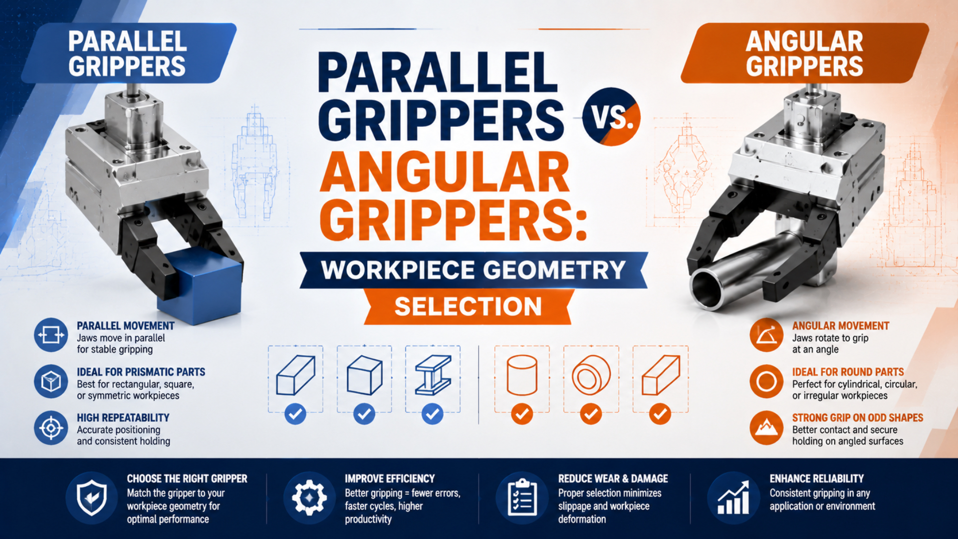
Draw the contact first. Labels such as flat, round, and irregular cannot choose between parallel and angular grippers. Parallel jaws are usually easier to apply when finger orientation must remain constant. Angular jaws become valuable when their swept path clears a nest, wall, conveyor guide, or loading route. Roundness does not decide the mechanism. A two-jaw parallel gripper fitted with V-shaped or contoured fingers can center many cylindrical workpieces. Nor does angular motion guarantee that an irregular casting will center. That result depends on the complete contact geometry, friction, part freedom, and synchronization of the jaws.
Key Takeaways
- Festo sizes grippers from object mass, surface quality, and jaw length.
- Parallel jaws preserve finger orientation through the stroke.
- Angular jaws trade constant orientation for a swinging clearance path.
- SMC uses 10 to 20 times workpiece weight as an initial force guideline, with more margin for impact.
Workpiece contact geometry is the combination of allowed contact zones, local surface shape, finger profile, contact-normal direction, dimensional tolerance, and the path each finger follows before and after gripping. It determines whether a gripper locates, clamps, marks, ejects, or misses the part.
Why Does Contact Geometry Come Before Gripper Type?
Festo’s gripper-sizing workflow asks for 3 application inputs that directly affect contact: object mass, surface quality, and gripper-jaw length. It then compares parallel, angular, and centric motion rather than assigning a gripper from the part name alone (Festo Gripper Sizing, retrieved 2026-07-27).
Start by marking every surface that may be touched and every surface that must remain untouched. Then add the part’s center of gravity, orientation during motion, dimensional limits, surface condition, and permitted cosmetic pressure. This drawing is more useful than a note that says “round shaft” or “irregular casting.” The next question is whether the contact must remain normal to a flat surface while the part width changes. Parallel jaws preserve finger orientation, so their pads can stay aligned with opposing flats through the working stroke. Angular jaws rotate, which changes pad orientation and contact radius as the fingers close.
Jaw path also affects access. A parallel finger translates beside the workpiece. An angular finger sweeps around a pivot and may move away from a fixture wall faster after release. The preferred motion is the one that creates stable contact and a collision-free approach, grip, transfer, and release sequence. Treat “parallel versus angular” as a path-selection question before treating it as a force comparison. If two candidate grippers can both hold the part, the decisive constraint is often the space required by the custom fingers while opening, not the catalog width of the gripper body.
For the broader performance and safety comparison, use the parallel versus angular gripper engineering guide. The pneumatic gripper types overview covers centric, wide-opening, toggle, and multi-finger alternatives.
Parallel Grippers Are Not Limited to Flat Parts
Festo’s parallel-gripper selection aid includes a positive-locking V-gripper example with a 45-degree contact angle and a safety factor of 2. This documented case shows that shaped fingers can adapt parallel motion to cylindrical workpieces without changing the gripper into an angular mechanism (Festo Parallel Grippers, retrieved 2026-07-27).
Parallel grippers are a strong first choice when the part presents two opposing flats, a controlled outside diameter, an internal bore, or a feature that custom fingers can capture while translating. Their defining benefit is not “high force.” It is the predictable orientation of the finger relative to the gripper body. A cylindrical shaft can be held by V-grooved fingers, opposed concave pockets, replaceable inserts, or a combination of a locating feature and friction pad. The selected profile must accommodate the full diameter tolerance without allowing the part to bottom against the finger before adequate clamping develops.
For prismatic parts, flat pads can distribute contact pressure over a larger area. For thin sheets, a broad compliant pad may reduce marking, but it can also allow the part to shift under acceleration. For machined components, a pocket can locate a shoulder or flange and reduce dependence on surface friction. The limitation is the straight jaw path. A finger that fits perfectly at the closed position may collide with a nest wall while opening. Long custom fingers also increase moments at the base jaws. Confirm the permitted finger length and external loads from the exact model rather than assuming that a larger bore solves the problem.
The parallel pneumatic gripper mechanism guide explains how synchronized translation affects centering and guide loads. For difficult part profiles, pair it with the custom gripper finger design guide.
When Does an Angular Jaw Path Solve the Real Problem?
SMC’s MHC2 angular family uses a specified finger range from 30 degrees open to 10 degrees past the nominal closed reference for applicable models. That model-specific arc illustrates the actual advantage: fingers can swing through a changing envelope instead of translating beside the workpiece (SMC MHC2, retrieved 2026-07-27).
Choose angular motion when the open fingers must clear a fixture lip, approach through a narrow opening, move away from a conveyor guide, or release without dragging beside the workpiece. The complete arc must remain clear of the part, fixture, robot wrist, sensors, cables, and nearby guarding. Angular motion changes finger orientation. A flat pad may first contact an edge and then rotate toward broader contact. On a tapered or soft component, that changing direction can push the part upward, sideways, or deeper into the nest. A contoured finger can correct the contact, but only across the tolerance range used to design it.
Roundness alone is not a sufficient reason. A two-finger angular gripper can contact a round part at two points, yet the part may still shift if one finger touches first or the fixture constrains centering. When concentric location is the primary need, a three-finger centric gripper or a dedicated nest may produce a more direct load path. Standard-angle and 180-degree angular grippers also solve different clearance problems. Do not compare them as one category. Use the angular gripper mechanism guide to check opening angle, contact radius, linkage behavior, and the depressurized state for the selected model.
How Do External and Internal Grips Change the Choice?
At 0.5 MPa, SMC lists 21 N external and 23 N internal effective force for the MHS2-16D at its specified 20 mm gripping point. The two values differ even on the same parallel gripper, so grip direction must be fixed before comparing models (SMC MHS2, retrieved 2026-07-27).
An external grip closes onto the outside of the part. It is common for blocks, shafts, housings, bottles, and castings with accessible outer features. The fingers must avoid ejecting a tapered part and must not squeeze a thin wall beyond its allowable deformation. An internal grip expands inside a bore, ring, tube, or recess. It can leave outer cosmetic surfaces untouched and may place the contact nearer a useful locating diameter. However, the part must have adequate wall strength, insertion clearance, and a release path that does not drag the fingers through a sensitive bore.
Grip direction can reverse the preferred jaw path. A parallel gripper may expand into a bore while maintaining pad orientation. An angular gripper may enter with the fingers closed and then rotate into a shoulder, but the finger tips must clear the bore during both insertion and withdrawal. Form closure and friction closure should also be separated. A friction grip relies on normal force and a conservative surface coefficient. A form-closure feature captures a shoulder, groove, flange, or hole and can reduce slip sensitivity. It may still require preload to control vibration and position.
For preliminary friction sizing, the Pneumatic Gripper Force Calculator can estimate required force per jaw. Treat that result as an input to the model-specific force curve, not as confirmation that the chosen fingers, guide loads, or part stresses are acceptable.
Finger Geometry Controls Contact, Centering, and Damage
SCHUNK lists a 50 mm maximum permissible finger length for the MPG-plus 40 variant and distinguishes its force at zero finger length from the rated closing force. This is why custom finger geometry must be reviewed with the gripper’s permitted load data, not only its nominal force (SCHUNK MPG-plus 40, retrieved 2026-07-27).
Use flat pads when the part offers broad, opposing surfaces and small position variation. Compliant pads protect surfaces. They may also raise friction, but compression, wear, contamination, and temperature can reduce repeatable location. Use V grooves for round sections when two lines of contact provide acceptable centering and pressure. The groove angle, part diameter range, edge radii, and pad stiffness determine whether both sides contact as intended. Reject any design that lets a shaft balance on one sharp edge while the opposing finger remains unloaded.
Contoured pockets suit castings, molded parts, and asymmetric profiles. Separate location from clamping. If every surface attempts to locate the part simultaneously, normal tolerance variation can create rocking, incomplete seating, or excessive local pressure. In our experience, coloring the planned contact zones on the part drawing exposes ambiguity before detailed finger design begins. Use one color for hard location, another for compliant clamping, and a third for prohibited contact. Mechanical, controls, quality, and purchasing teams can then discuss the same finger function without relying on different verbal interpretations.
Keep the contact point close to the base jaw when practical. Longer fingers amplify moment from workpiece weight, acceleration, misalignment, and collision. Also check finger mass and inertia for angular grippers because the mechanism must accelerate and stop the attachment through its full arc.
How Should Tolerance and First Contact Be Checked?
The SMC MHZ2 range shows total opening and closing strokes from 4 mm on smaller models to larger model-specific values, while force is stated at defined gripping-point distances. Stroke and force therefore need separate tolerance checks; unused catalog stroke is not automatically usable finger clearance (SMC MHZ2, retrieved 2026-07-27).
Create minimum, nominal, and maximum workpiece models. Add finger machining tolerance, mounting location tolerance, jaw repeatability, guide play, pad compression, fixture position, and robot or slide positioning error. The objective is not merely to prove that the jaws can close around the nominal CAD model. Identify the first possible contact at every tolerance condition. With a parallel gripper, one side may touch early because the part sits off-center in the nest. With angular fingers, the contact angle can change with part size, so a larger part may meet the pad at an edge before the designed contact surface arrives.
Then identify the no-part closed position. The fingers must not collide with each other, the fixture, or a hard stop in a way that damages the gripper. Sensor logic should distinguish an empty close from the accepted part window whenever a missed pick can continue into the process. For round and tapered parts, inspect whether the force direction pulls the part into its nest or pushes it out. For thin parts, check buckling and local indentation. For compliant parts, include the deformed geometry because the contact location can migrate as pressure rises.
One closed-position section is insufficient. Compare fully open, first possible contact, nominal grip, and fully closed without a part. Release collisions and false-positive sensor states often become visible only when those four conditions are reviewed together.
A Geometry-First CAD and Sample Validation Workflow
SMC divides angular-gripper selection into 3 checks: gripping force, gripping point, and attachment inertia. That sequence is a useful reminder that the same finger drawing affects holding capacity, jaw loading, and dynamic behavior at once (SMC MHC2 Model Selection, retrieved 2026-07-27).
Use this validation workflow:
- Freeze the part family. Collect drawings, mass, center of gravity, tolerance limits, surface condition, temperature, and known defects such as burrs or flash.
- Mark contact functions. Separate hard location, clamping, surface protection, and prohibited zones.
- Model both jaw paths. Compare straight translation and angular sweep using realistic finger bodies, fasteners, sensors, and mounting adapters.
- Check every state. Review open, first contact, accepted grip, empty close, release, and withdrawal.
- Review loads. Use point-of-use pressure, acceleration, friction, contact distance, finger mass, and the manufacturer’s permissible load curves.
- Build representative fingers. Use production material, coatings, pad hardness, edge radii, and fastener arrangement.
- Test the tolerance set. Include minimum, nominal, maximum, oily, dry, warm, cold, and cosmetically sensitive samples where applicable.
- Record acceptance. Document seating, position window, marking, deformation, slip, collision clearance, sensor response, and release behavior.
Test under production motion. A vertical static hold does not prove retention during robot acceleration, abrupt stop, or a horizontal move with the same orientation. Likewise, a clean sample cannot represent a production part covered with coolant, dust, release agent, or condensation. Use controlled pressure at the gripper and record it during motion and contact. Static regulator pressure can look acceptable while simultaneous actuators create a dynamic pressure drop. If the geometry passes but the part slips only at peak demand, separate the air-supply issue from the finger design.
Machine safety remains a separate release gate. ISO 4414 specifies general requirements for pneumatic systems and components, but the complete machine risk assessment must define the acceptable response to air loss, emergency stop, sensor disagreement, and a dropped workpiece (ISO 4414:2010, confirmed 2021; retrieved 2026-07-27).
What Should a Geometry-Focused RFQ Include?
Festo’s sizing workflow can return as many as 3 solutions after the application inputs are entered: an exact result, a cost-efficient option, and a high-force or high-torque option. A useful RFQ must therefore describe the application well enough to compare tradeoffs, not request only a bore size (Festo Gripper Sizing, retrieved 2026-07-27).
Send the following:
| RFQ field | Geometry information required |
|---|---|
| Workpiece | Drawing, 3D model, mass, center of gravity, and tolerance limits |
| Contact zones | Allowed, preferred, cosmetic, coated, fragile, and prohibited surfaces |
| Grip direction | Internal or external, plus required workpiece orientation |
| Finger function | Locate, friction clamp, form capture, protect, or release |
| Motion | Approach direction, acceleration, stop profile, cycle rate, and withdrawal path |
| Fixture | Nest, walls, guides, neighboring tools, sensors, and collision keep-out zones |
| Environment | Oil, dust, water, washdown, temperature, and abrasive contamination |
| Air and control | Dynamic pressure, valve state, sensing requirement, and air-loss response |
| Acceptance | Position window, permitted marking, maximum deformation, and sample-test conditions |
Attach annotated screenshots of the four required finger states. Include the minimum and maximum part models, not only the nominal assembly. If a supplier proposes both parallel and angular solutions, ask for the contact-point definition, finger length, force curve, allowable jaw loads, open envelope, and assumptions used for each. Do not approve “drop-in replacement” from mounting dimensions alone. Port location, sensor position, jaw interface, force definition, permissible finger loads, stroke, repeatability, air consumption, mass, and safe-state behavior can differ. Freeze the complete order code and released finger drawing.
Parallel vs. Angular Gripper FAQs: What Should Engineers Check?
SMC’s model-selection guidance uses an initial gripping-force range of 10 to 20 times workpiece weight and calls for additional margin under acceleration or impact. The 5 answers below keep that force screen separate from contact geometry, finger path, part tolerance, fixture clearance, and sample validation (SMC MHC2 Model Selection, retrieved 2026-07-27).
Can a parallel gripper hold a cylindrical workpiece?
Yes. Parallel jaws can use V grooves, concave pockets, compliant inserts, or feature-capturing fingers to hold many cylindrical parts. Verify the full diameter tolerance, contact on both fingers, surface pressure, centering freedom, and release clearance. Round geometry alone is not a technical reason to select an angular gripper.
Do angular grippers automatically center irregular parts?
No. Symmetric jaw motion does not guarantee that the workpiece centers. One finger may contact first, and the rotating pad can push the part along an unintended direction. Centering depends on finger contour, contact normals, friction, fixture freedom, part tolerance, and whether the mechanism keeps both jaws synchronized under load.
Which gripper is safer for fragile parts?
Neither type is inherently safer. Fragile-part performance depends on contact area, pad compliance, pressure control, finger stiffness, closing speed, part support, and local stress. Parallel motion can maintain pad orientation, while angular motion can change the approach angle. Test production samples at worst-case tolerance and pressure before release.
Is an angular gripper always more compact?
No. Body width is only one dimension. An angular gripper may have a compact body but require a large swept finger envelope. A parallel model may be wider yet fit the station because its fingers translate inside available space. Compare the complete open, closing, gripped, and withdrawal envelopes in CAD.
What information matters most when comparing two models?
Compare force at the real contact point, allowable finger length and jaw loads, opening range, finger path, dynamic pressure, part tolerance, fixture clearance, sensor windows, and response after air loss. Nominal bore or maximum force alone cannot establish equivalence. Use the released finger drawing and sample-test record as part of approval.
Sources and technical references
- Festo Gripper Sizing, application inputs and comparison workflow; retrieved 2026-07-27.
- Festo Parallel Grippers HGPT, HGPL and HGDS, V-gripper selection example and gripping-force principles; retrieved 2026-07-27.
- SMC MHZ2 Parallel Type Air Gripper, stroke, pressure, force, and gripping-point data; retrieved 2026-07-27.
- SMC MHC2 Angular Type Air Gripper, angular motion and model-specific product data; retrieved 2026-07-27.
- SMC MHC2 Model Selection, gripping-force, gripping-point, attachment-inertia, and safety-margin guidance; retrieved 2026-07-27.
- SMC MHS2 Parallel Type Air Gripper, internal and external effective-force definitions; retrieved 2026-07-27.
- SCHUNK MPG-plus 40, finger-length, force, pressure, and acceleration assumptions; retrieved 2026-07-27.
- ISO 4414:2010, pneumatic fluid-power system and component safety requirements; confirmed 2021; retrieved 2026-07-27.