

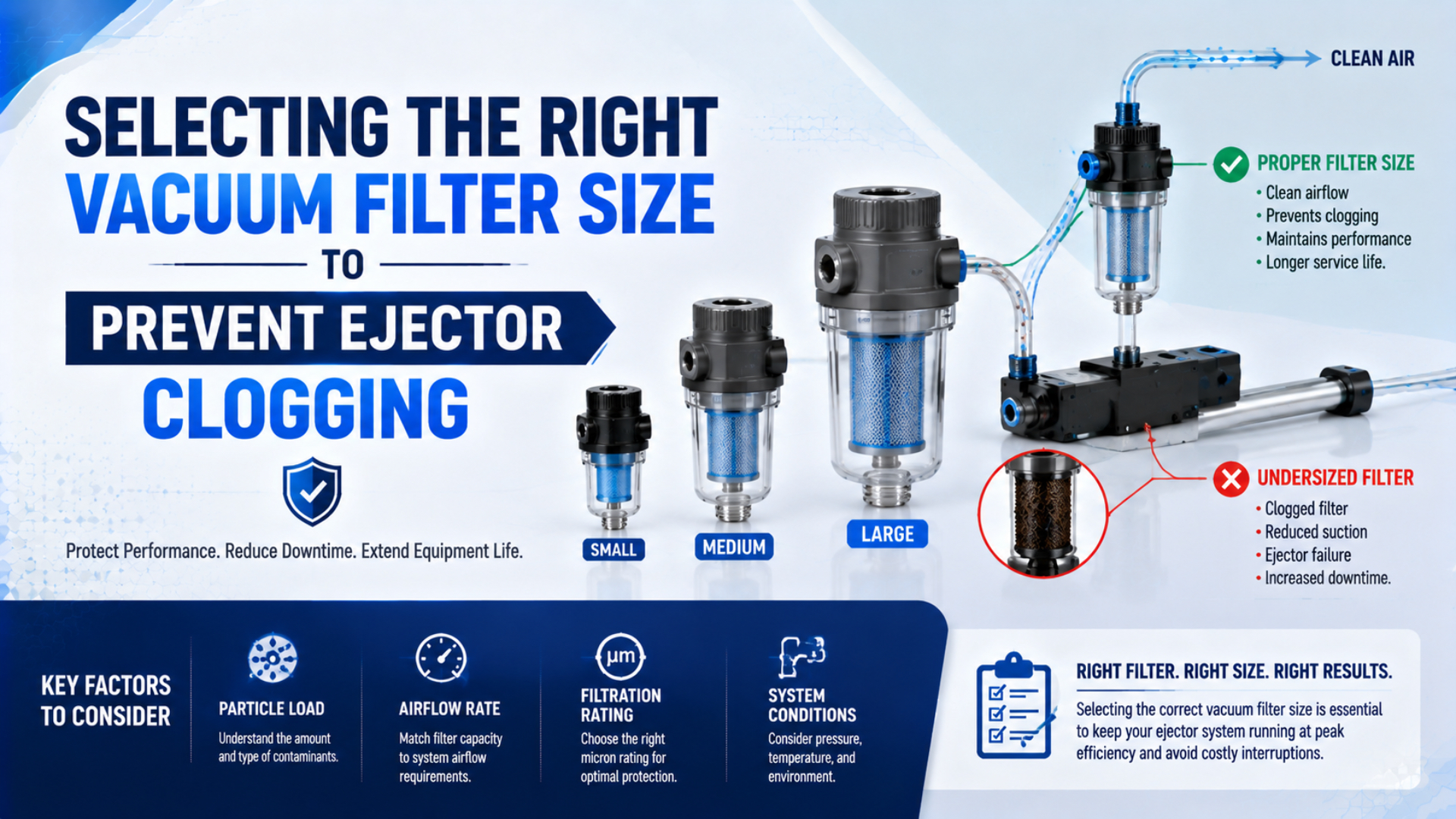
The right vacuum filter size is the model that passes the required suction flow at the system’s actual vacuum level without exceeding the permitted pressure drop, including an allowance for element loading. It must also provide a documented particle-removal rating for the contaminant and withstand the intended vacuum, temperature, media, cleaning method, and blow-off cycle.
Do not size a vacuum-side filter from the ejector’s compressed-air consumption. Motive air and suction flow belong to different flow paths. Select the supply-side air treatment from the ejector’s inlet-air demand and air-quality requirement. Select the vacuum-side filter from the suction demand between the workpiece and the ejector.
Key Takeaways
- Size supply and vacuum filters from their own flow paths.
- Check pressure drop on a vacuum-flow curve at the target vacuum.
- Specify filtration efficiency, not a micron number alone.
- One SMC ZFC range lists vacuum flows of 2-100 L/min, depending on model.
In this guide
- What Does “Vacuum Filter Size” Mean in an Ejector Circuit?
- Why Must Supply-Side and Vacuum-Side Filters Be Sized Separately?
- Data Required Before Selecting a Vacuum Filter
- How Do You Match Vacuum Flow to a Filter Curve?
- Filtration Grade Is a Product Specification
- Where Should Filters Sit in Multi-Cup Systems?
- How Should Restriction and Element Loading Be Monitored?
- What Belongs in a Vacuum Filter RFQ?
- Vacuum Filter FAQs
What Does “Vacuum Filter Size” Mean in an Ejector Circuit?
Vacuum filter size is not simply the thread stamped beside a port. It is a combination of pneumatic capacity and filtration performance. The relevant product data normally include a port or tube size, recommended flow, pressure-drop curve, filtration grade and efficiency, element area, internal volume, pressure range, and environmental limits.
Two filters with G1/8 ports can have different media areas and very different restriction. A larger port can also lead into a small element. Port compatibility matters for installation, but it doesn’t prove that the filter will pass the required flow.
The operating point matters just as much as nominal flow. SMC’s current ZFC catalog, for example, lists positive-pressure flow ranges of 15-650 L/min and vacuum-pressure flow ranges of 2-100 L/min across different models. The same catalog provides separate flow-characteristic graphs rather than one capacity value for every condition (SMC ZFC catalog).
This distinction is especially important during fast evacuation. A filter that supports steady leakage after a part is gripped can still slow the initial pump-down. Conversely, choosing a very large housing without checking internal volume may add dead volume near the cup. The correct selection balances clean pressure drop, loaded pressure drop, response time, available space, and service access.
The required result should be written as an operating envelope, not as “use a 1/4-inch filter.” A useful requirement states the suction flow at target vacuum, maximum acceptable clean and service-limit pressure drops, filtration performance, contaminant, and expected maintenance method.
Why Must Supply-Side and Vacuum-Side Filters Be Sized Separately?
A Venturi ejector has a compressed-air inlet and a vacuum inlet. Compressed air passes through the nozzle and diffuser to create suction. The vacuum inlet draws air from the cup, fixture, or process. These streams interact inside the ejector, but their flow values are not interchangeable.
The supply side protects the nozzle, valve, and pressure-sensing components from compressed-air contamination. SMC’s ZK2 manual recommends upstream air filtration and mist separation, specifies an ISO 8573-1 supply-air cleanliness class for that product, and warns that contaminants can adhere to internal components and reduce performance (SMC ZK2 operation manual). Apply the current manual for the exact ejector being specified, because the required air-quality class can differ by product.
The ISO 8573-1 compressed-air quality guide explains how particle, water, and oil classes are stated. Those classes belong in the supply-side specification only when the ejector manufacturer or plant standard requires them.
Size that supply treatment from:
- maximum ejector air consumption at the selected inlet pressure;
- simultaneous demand from all active ejectors;
- allowable inlet pressure loss at peak flow;
- required particle, water, and oil control;
- compressor and distribution-system conditions.
The vacuum-side filter protects the suction port from material drawn through a cup or process connection. Size it from:
- peak suction flow during evacuation;
- leakage after the part is sealed;
- target vacuum level;
- permitted pressure loss between cup and ejector;
- contaminant size, concentration, and loading rate.
Compressed-air consumption in L/min cannot be converted directly into a filter Cv by multiplying it by a safety factor. L/min is a flow under stated reference conditions, while Cv is a coefficient used in a pressure-flow relationship. More importantly, the motive-air value is not the suction flow that the vacuum filter carries.
For ejector fundamentals, including the relationship between supply pressure, nozzle geometry, suction flow, and attainable vacuum, see The Physics of Venturi Ejectors and Vacuum Control Valves.
Data Required Before Selecting a Vacuum Filter
Start with the ejector curve and the process duty. Record the unit conventions used by the manufacturer, because “normal” liters and actual volumetric flow are not automatically equivalent.
| Input | Why it matters | Evidence to request |
|---|---|---|
| Ejector model and nozzle option | Establishes the correct suction curve | Current datasheet and configured part number |
| Target vacuum | Locates the real operating point | Process limit and ejector curve |
| Peak evacuation flow | Sets the filter’s short-duration capacity | Cycle profile or validated model |
| Sealed leakage | Sets holding demand after pickup | Leak test at representative surfaces |
| Number of simultaneous branches | Determines combined flow | Valve sequence and worst-case state |
| Maximum filter pressure drop | Protects cup vacuum and response time | System pressure budget |
| Contaminant | Drives media and grade choice | Sample, process knowledge, or particle analysis |
| Loading rate | Determines service interval and element area | Mass collected per cycle or timed inspection |
| Blow-off arrangement | May reverse flow through the filter | Circuit diagram and filter limit |
| Environment | Affects housing, seals, and media | Temperature, chemistry, humidity, washdown data |
Use the worst credible operating combination, not a single average. A porous carton, rough casting, or warped sheet can introduce leakage that is absent during a bench test with a sealed cup. Several vacuum branches may open together even if they normally sequence one at a time.
Evacuation flow also changes through the cycle. It is high while the line and cup volume are near atmospheric pressure, then falls as vacuum develops. The ejector’s free-air suction value does not by itself prove the flow available at the target vacuum. Read the complete suction-flow curve.
The Vacuum Evacuation Time Calculator can help compare volume, target vacuum, leakage, and cycle-time sensitivity. Treat its result as a system estimate. The filter still needs to be checked against the manufacturer’s own vacuum-flow and pressure-drop data.
In my application reviews, I found that treating the vacuum filter as part of the complete vacuum-line pressure budget produces a better diagnosis. Tube length, fittings, valves, filter media, and manifolds all consume part of that budget. Checking only the filter can hide a restrictive elbow or undersized tube immediately beside it.
The same system-level check is used when diagnosing flow starvation in pneumatic systems. A component’s catalog capacity cannot compensate for restrictions elsewhere in the installed path.
How Do You Match Vacuum Flow to a Filter Curve?
Find the operating point on a vacuum-specific flow curve. The horizontal and vertical axes vary between manufacturers, so read the test conditions and units before comparing products. A positive-pressure curve is not a substitute for a vacuum-flow curve.
Follow this selection sequence:
-
Identify peak required suction flow. Include every branch that can draw simultaneously. Use the ejector curve at the relevant vacuum, plus measured leakage where available.
-
Set the allowable pressure-drop budget. Decide how much vacuum can be lost between the workpiece and ejector without violating grip force, process limit, or evacuation time.
-
Read clean-element performance. Confirm that the candidate passes the required flow at the target vacuum within the clean pressure-drop limit.
-
Define a loaded-element limit. Establish the differential pressure or performance change that triggers service. Use the product manual’s limit when it provides one.
-
Check transient behavior. Verify evacuation time with the filter, line volume, valves, and real leakage. A holding-state check alone is incomplete.
-
Check every limit. Confirm allowable vacuum, positive pressure if blow-off is used, temperature, media, mounting orientation, housing strength, and element compatibility.
An older SMC ZFC catalog illustrates why the conditions must travel with a flow number. It lists recommended flows of 10, 20, 30, and 50 L/min for different sizes when initial pressure drop is no more than 3 kPa. Those numbers describe that product range and test condition, not a universal filter-size table (SMC ZFC technical data).
Don’t substitute a pipe-flow equation or a compressed-air Cv table when the manufacturer publishes measured vacuum-filter curves. Media restriction changes as dust accumulates, and many catalogs report empirical product performance more directly than a single idealized coefficient can.
If the curve leaves little margin between the clean operating point and the permitted service limit, compare the next housing size or a larger-area element. The purpose of margin is to accommodate documented loading and variability, not to apply a fixed percentage to every system.
Filtration Grade Is a Product Specification
A micron value is incomplete unless it is paired with removal efficiency and test conditions. “10 µm” can mean a nominal rating, an efficiency at a stated particle size, or another supplier-defined convention. Read the catalog definition before comparing filters.
The distinction is explained in Absolute vs. Nominal Micron Filter Rating. In an RFQ, ask for the efficiency curve or the exact rating method rather than accepting an isolated micron number.
Current manufacturer data also show why one environment-to-micron chart is unreliable:
| Official product example | Published grade or efficiency | Relevant published flow data |
|---|---|---|
| SMC ZFC | Standard 5 µm at 95%; optional 10 µm in the cited catalog | Vacuum flow 2-100 L/min, model dependent |
| Festo ESF | 10 µm | Nominal flows 100, 260, and 270 L/min at -0.075 MPa |
| Festo VAF-PK | 50 µm | Nominal flows 50.8, 70, and 210 L/min at -0.075 MPa |
| Festo VAF-DB | 80 µm | Product-specific sizing data in the same catalog |
| Festo OAFF | 40 µm | Product-specific sizing data in the same catalog |
| Piab inline vacuum filters | Product variants include 5, 10, and 50 µm | Select by the exact product’s data and connection |
The Festo figures come from its vacuum-filter technical documentation (Festo vacuum filters). Piab publishes separate vacuum-filter products and variants rather than one universal grade (Piab 5 and 10 µm vacuum filter; Piab 50 µm inline filter).
These examples do not prove that finer is always better. Finer media may reduce particle penetration, but it can also create more restriction or load sooner. Coarser media may protect against larger debris while preserving flow. The correct choice depends on what must be stopped, the efficiency required, the available pressure budget, and the service plan.
When I compared the cited catalogs, I found that products described as vacuum filters span at least 5, 10, 40, 50, and 80 µm grades. That range is evidence against selecting a grade from a generic “clean” or “dusty” environment label alone. Each grade still needs its product-specific efficiency and flow data.
Media construction matters too, but broad labels such as paper, plastic, or metal do not establish suitability. Verify the exact element’s collapse resistance, cleanability, chemical compatibility, moisture behavior, shedding risk, and response to reverse flow. If the vacuum line can see blow-off pressure, confirm that condition explicitly.
For processes with airborne dust, the pneumatic contamination-control guide provides a broader method for locating ingress paths and planning inspections. Vacuum-side media still needs its own verified curve and rating.
Where Should Filters Sit in Multi-Cup Systems?
Place a vacuum filter where it intercepts contamination before it reaches the ejector and can be inspected without opening a dirty line over sensitive equipment. Keep the connection volume and restriction consistent with the required response time.
A central filter protects one ejector or manifold with fewer service points. It may be appropriate when branches see similar contamination and a single restriction cannot disable an unsafe load without detection. Its capacity must cover the simultaneous flow of the connected branches.
The decision resembles the tradeoff between centralized and point-of-use air treatment, but the vacuum circuit needs separate flow, failure, and blow-off checks.
Branch filters near individual cups can localize contamination and make a dirty pickup easier to identify. They add components, connections, dead volume, and maintenance points. Unequal loading can also make branch performance diverge over time.
Use these questions to choose the layout:
- Can one contaminated branch expose the common manifold?
- Would one loaded central element stop every pickup point?
- Are the branch flows and contaminants similar?
- Can maintenance reach and identify each filter?
- Is blow-off common or branch-specific?
- Does the safety analysis tolerate a shared restriction?
In multi-cup layout reviews, I found that the number of filters follows the contamination and failure boundaries, not the number of cups. There isn’t a universal rule that every cup needs its own filter. Map the contamination source, failure consequence, service access, and flow paths. Then compare central and distributed layouts under both clean and loaded conditions.
Avoid installing a general compressed-air line filter on the vacuum side unless its manufacturer explicitly rates it for that service. A housing designed for positive pressure can behave differently under external pressure, and its drain, bowl, seals, and flow data may not suit vacuum. The coalescing filter guide covers supply-side oil-aerosol removal, which is a different duty from trapping process dust in a suction line.
How Should Restriction and Element Loading Be Monitored?
Establish a clean baseline after commissioning. Record vacuum at the cup or manifold, vacuum at the ejector inlet when practical, evacuation time, supply pressure at the ejector, and the machine state used for the test. A later change is useful only when the reference condition is repeatable.
Differential pressure across the element is the most direct measure of restriction when the filter provides suitable ports or an indicator. Otherwise, track a combination of evacuation time and vacuum readings under the same test state. A vacuum reading taken only at the ejector can hide loss between the ejector and cup.
Do not impose a generic replacement interval such as every 500 hours. Dust concentration, particle properties, duty cycle, humidity, element area, and blow-off behavior can change element life substantially. Inspect more frequently during commissioning, then set the interval from measured loading and the manufacturer’s service criteria.
The current SMC ZFC catalog gives a product-specific replacement criterion of 0.1 MPa differential pressure for positive-pressure use and 20 kPa for vacuum-pressure use. Apply those figures only to the cited models and current instructions. Another filter may have a different limit or no permissible cleaning procedure.
When vacuum performance falls, compare the clean baseline in this order:
- Confirm supply pressure at the ejector while it is consuming air.
- Check cup seal, workpiece porosity, tubing, fittings, and valves for leakage.
- Measure restriction across the vacuum filter or temporarily test with a verified clean element.
- Inspect the ejector according to its manual if supply and vacuum-line conditions are correct.
- Restore guards and validate pickup, holding, blow-off, alarms, and safe failure behavior.
Never run production without required filtration merely to regain cycle time. A temporary diagnostic change should be controlled, brief, and followed by restoration of the approved circuit.
What Belongs in a Vacuum Filter RFQ?
A precise RFQ prevents a supplier from matching only the port size. Include:
- ejector manufacturer, model, nozzle option, and supply pressure;
- suction-flow requirement at the target vacuum;
- peak and steady operating states;
- number of simultaneous cups or branches;
- permitted clean and service-limit pressure drops;
- contaminant description and expected loading;
- required particle-removal efficiency and its test basis;
- housing and element material constraints;
- temperature, humidity, chemicals, and washdown exposure;
- vacuum range, any positive blow-off pressure, and flow direction;
- port or tube connection, mounting, envelope, and service clearance;
- indicator, differential-pressure port, or sensor requirement;
- replacement-element part number and acceptable cleaning method;
- sample or first-article validation plan.
Ask the supplier to return the exact curve and operating point used for selection. A catalog screenshot without axes, test conditions, or model identity is not sufficient. Record the document revision with the approved part number.
For a multi-source program, distinguish dimensional fit from functional equivalence. Two filters may connect to the same tube and still differ in media efficiency, internal volume, pressure loss, blow-off rating, and element availability. Validate each proposed alternate against the same RFQ and machine acceptance test.
Vacuum Filter FAQs
Should vacuum-side filter size be based on ejector air consumption?
No. Ejector air consumption describes the compressed-air supply path. A vacuum-side filter carries air drawn from the process. Size it from suction flow at the actual target vacuum, leakage, simultaneous branches, and the permitted vacuum-line pressure drop.
Is a smaller micron rating always better?
No. A finer grade can improve particle capture, but it may add restriction or load faster. Compare efficiency at the stated particle size, flow and pressure-drop data, element area, contaminant loading, and the ejector’s protection requirement.
Can a standard compressed-air filter be installed on the vacuum line?
Only when the manufacturer explicitly approves that product for vacuum service and the application stays within its ratings. Confirm housing behavior under vacuum, flow direction, drain and seal design, media, pressure-drop data, and any reverse-flow blow-off condition.
Does every suction cup need its own filter?
Not necessarily. Branch filters localize contamination, while a central filter reduces component count. Choose from simultaneous flow, cross-contamination risk, failure consequence, service access, dead volume, and the machine’s safety analysis.
When should a vacuum filter element be replaced?
Use the manufacturer’s service limit and a commissioned baseline. Differential pressure, evacuation time, and vacuum loss under a repeatable test state are better triggers than a universal hour interval. Replace damaged media and follow only the approved cleaning procedure.