

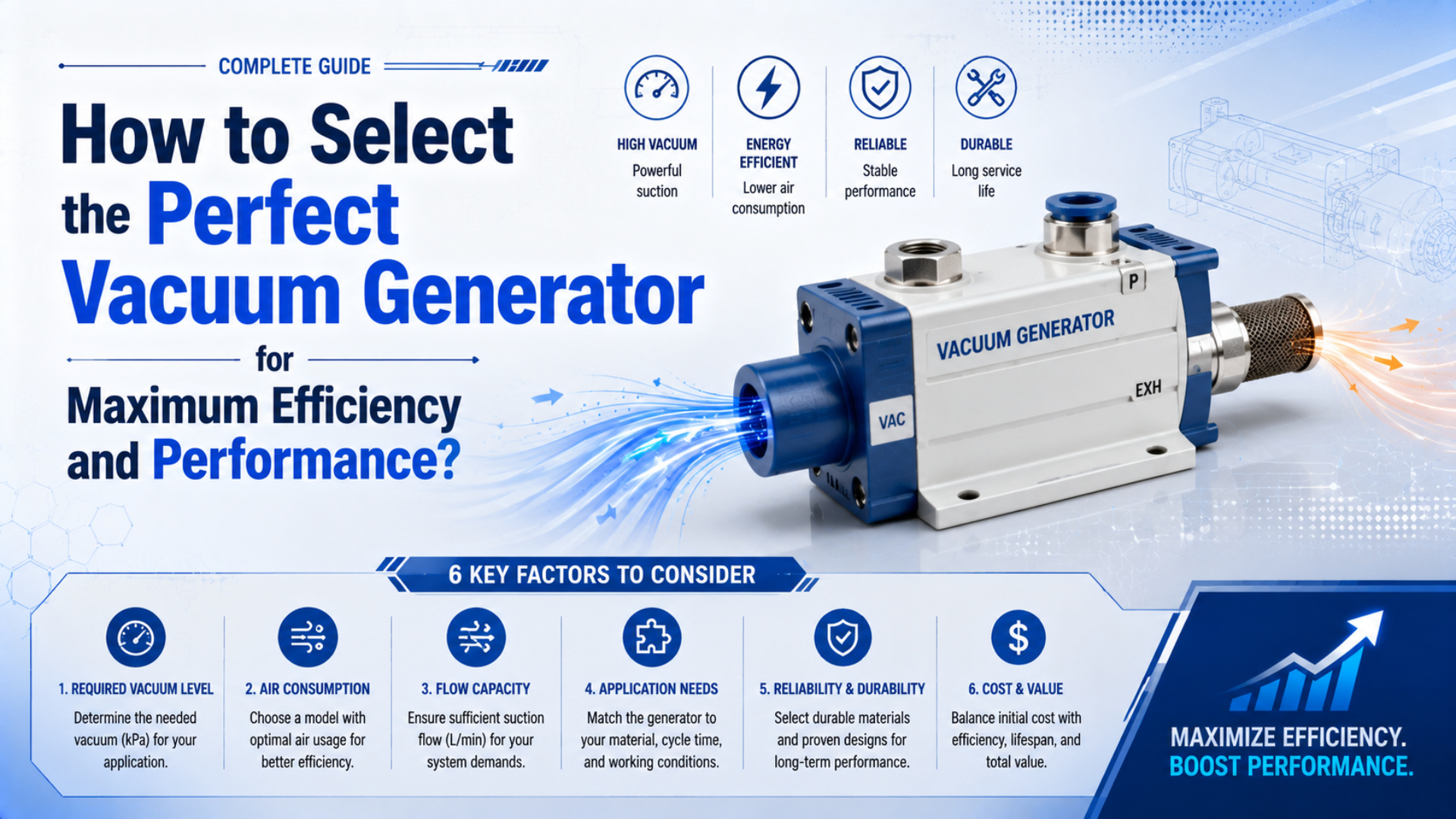
A vacuum generator is the device that evacuates the cup and connected circuit. To select a vacuum generator, choose the smallest unit that reaches the verified pick pressure within the allowed time, sustains it at measured leakage, and meets air-cost and safety limits. Maximum vacuum, maximum suction flow, and air consumption remain separate catalog values.
Start with the load, cup arrangement, surface, total evacuated volume, target response time, expected leakage, dynamic inlet pressure, duty cycle, and release method. Then compare each candidate at one common operating point. The final decision comes from a test on the actual workpiece, not from combining unrelated catalog maxima.
Key Takeaways
- Size cup holding force and generator flow as separate checks.
- Read suction flow at the required vacuum, not at the curve endpoint.
- SMC’s ZQ examples pair 5-22 L/min suction flow with 15-47 L/min motive-air use.
- Prove pick pressure, response time, leakage recovery, release, and safe failure on the machine.
The Vacuum Generator Selection Data Sheet
SMC’s current model-selection sequence uses seven steps, ending with evaluation on the actual equipment. That order is useful because generator capacity cannot be finalized before the workpiece, motion, cup geometry, and required holding force are known (SMC Vacuum Equipment Model Selection, 2026).
Write the operating requirement before opening a catalog. A usable data sheet contains:
| Input | Record this value | Why it changes the selection |
|---|---|---|
| Workpiece | mass, dimensions, center of gravity, surface, porosity | determines load, cup type, leakage, and load sharing |
| Motion | orientation, acceleration, deceleration, vibration | determines required holding margin |
| Vacuum circuit | cup count, cup volume, tube ID and length, manifold volume | determines evacuated volume and conductance |
| Timing | maximum time from vacuum command to safe-pick signal | determines required effective suction flow |
| Leakage | measured flow or pressure reached on the actual part | moves the operating point along the flow curve |
| Plant air | dynamic pressure at the generator, air quality, simultaneous demand | determines whether catalog performance is achievable |
| Controls | vacuum switch, check valve, shutoff logic, blow-off, fault response | determines air on-time and safe release |
| Commercial duty | generator count, cycles, holding time, shifts, energy price | determines annual compressed-air cost |
Treat the result as an operating envelope, not a single vacuum number. A concise requirement might read: “Maintain at least -55 kPa gauge while drawing 12 L/min of measured leakage, reach the switch point within 180 ms, and operate from 0.40 MPa dynamic inlet pressure.” That statement can be checked against a curve and a machine test.
How Do You Separate Cup Holding Force From Generator Capacity?
Schmalz defines ideal suction-cup holding force as pressure difference multiplied by effective suction area, . The relationship sizes the load side; it does not state the suction flow needed to evacuate tubing or replace leakage (Schmalz Vacuum Suction Cups, 2026).
The ideal normal holding force is:
In this equation, is the ideal normal force, is ambient pressure minus cup pressure, and is the manufacturer’s effective suction area. Use pressure and area in compatible SI units to obtain newtons.
For a vertical upward move, a screening load can be written as:
In this expression, is workpiece mass, is gravitational acceleration, is upward acceleration, and is a chosen design factor. Distribute the required force across cups only after considering center of gravity, unequal load sharing, workpiece bending, cup wear, contamination, and the consequence of one cup losing its seal.
Vertical faces require a separate sliding check because the load acts tangentially to the cup. Friction coefficient, oil, water, dust, and surface texture can dominate. Don’t reuse the normal-force equation as proof of shear capacity. Use published shear data or test the exact cup and surface. Test both.
A generator does not create extra holding force after the required pressure is reached. Its flow capacity determines how fast pressure develops and whether the system can maintain that pressure while air leaks in. Flow is separate. Use the Vacuum Cup Size Calculator for an initial load-side screen, then obtain the cup manufacturer’s effective-area and shear data.
How Should You Read a Vacuum Generator Performance Curve?
At their stated supply pressures, SMC ZQ105, ZQ107, and ZQ110 examples list maximum suction flows of 5, 10, and 22 L/min (ANR), while all three list -80 kPa maximum vacuum. Those values occur at different curve endpoints (SMC ZQ Series, 2023).
Maximum vacuum is measured with the suction port sealed, where suction flow approaches zero. Maximum suction flow is measured near atmospheric pressure at the suction port, where usable vacuum is low. A workpiece operates somewhere between these endpoints.
Read a candidate curve in this order:
- Mark the minimum acceptable vacuum pressure from the load check, including acceleration and the permitted pressure loss before the controller reacts.
- Intersect that pressure with the candidate’s suction-flow curve.
- Read the flow.
- Compare it with measured continuous leakage and the project’s required margin.
- Check evacuation-time data at the same supply pressure, tube, filter, volume, and pressure target.
- Record motive-air consumption at the dynamic inlet pressure rather than the plant header’s idle reading.
What if a catalog shows only “maximum vacuum” and “maximum flow”? Ask for the complete curve because combining those two maxima creates a fictional operating point.
Supply pressure also belongs to the comparison. The ZQ examples specify 0.35 MPa for the 0.5 mm nozzle and 0.43 MPa for the 0.7 and 1.0 mm nozzles. More inlet pressure is not a universal upgrade. The SMC selection guide recommends the model’s standard supply pressure and warns that excessive pressure can reduce performance as well as waste air.
For the nozzle, entrainment, and diffuser physics behind the curve, see The Physics of Venturi Ejectors and Vacuum Control Valves.
How Do Volume, Leakage, and Response Time Determine Flow?
Adsorption response time is the interval from valve operation until the cup reaches the pressure required for suction. SMC starts its flow screen with vacuum-side piping capacity divided by required response time, then adds the actual leakage operating point from the flow curve (SMC Vacuum Equipment Model Selection, 2026).
The evacuated volume includes cups, fittings, filters, tubes, manifolds, reservoirs, and sensor cavities. Long vacuum tubing adds volume and restriction. When response time matters, locating the ejector near the cups often works better than routing a long suction line to a remote cabinet.
For a closed volume and approximately constant effective pumping speed, a first screening estimate is:
In the estimate, is time, is total evacuated volume, is effective suction flow at the connected volume, and and are initial and final absolute pressures. Leybold uses volume, effective pumping speed, and pressure ratio for pump-down estimates, while noting that pressure-dependent speed and gas inflow change the result (Leybold Pump-Down Time, 2026).
An ejector’s suction flow usually changes as vacuum rises, so the equation is a screen rather than a release criterion. Use the manufacturer’s evacuation curve when available. Then test the installed volume. The Vacuum Evacuation Time Calculator helps organize volume, absolute pressure, leakage, and efficiency assumptions before that catalog check.
Porous board, textured castings, warped sheet, and worn cups add continuous leakage. Measure it with the actual workpiece. One practical method is to record the stabilized vacuum with the candidate ejector, then use that model’s flow curve to estimate the corresponding suction flow. Repeat across representative parts, not only the best-sealing sample.
Choosing Between High-Vacuum, High-Flow, and Centralized Sources
In SMC’s worked curve example, 40 L/min leakage leaves a high-vacuum ejector near -10 kPa but a high-flow version near -23 kPa; at 5 L/min leakage, the high-vacuum version reaches about -72 kPa. The application operating point determines which curve is useful (SMC Vacuum Equipment Model Selection, 2026).
| Source strategy | Usually fits | Main verification |
|---|---|---|
| High-vacuum ejector | sealed or low-leakage parts needing a deeper pressure differential | flow available at the holding setpoint |
| High-flow ejector | porous, rough, or inconsistent surfaces | sustainable vacuum at measured leakage |
| Multistage ejector | applications where its complete curve and motive-air demand outperform alternatives | model-specific curve, air consumption, exhaust and control data |
| Distributed ejectors | fast local response, short vacuum lines, independent cups | simultaneous compressed-air demand and noise |
| Central pump or blower | many points, long duty, continuous leakage, or plant-wide vacuum | line conductance, reserve, controls, maintenance, and total energy |
“Multistage” is a construction description, not an energy guarantee. Compare suction flow at the required pressure, motive-air flow at the stated supply pressure, and actual on-time. A single-stage unit with a well-matched nozzle and short duty may cost less to run than an oversized multistage unit left on continuously.
One generator feeding several cups creates a common-failure path. That matters. If one part is absent or one cup opens to atmosphere, vacuum can collapse at the remaining cups. Separate circuits, check valves, flow restrictors, or individual verification may be necessary. The correct arrangement follows the risk assessment, not the lowest component count.
Filters must be selected on the correct side of the circuit. The vacuum-side filter uses suction flow and allowable pressure drop; the supply-side filter uses motive-air demand and the generator’s inlet-air requirement. See Selecting the Right Vacuum Filter Size to Prevent Ejector Clogging for that separate calculation.
How Do You Compare Compressed-Air Cost Without Inventing Savings?
The same SMC ZQ examples pair 5, 10, and 22 L/min maximum suction flow with 15, 25, and 47 L/min (ANR) motive-air consumption. That spread shows why suction capacity and compressed-air demand must occupy separate columns in a bid comparison (SMC ZQ Series, 2023).
Annual electricity cost cannot be calculated from NL/min and electricity price alone. A defensible estimate needs normalized motive-air flow, generator count, measured on-time, annual operating hours, compressor specific power, and energy price:
The variables are normalized air flow , generator count , air-on duty fraction , annual operating hours , compressor specific energy , and electricity cost per kWh . Keep all volume reference conditions consistent.
The U.S. Department of Energy provides compressed-air assessment tools and a plant-cost worksheet rather than one universal cost factor (DOE Compressed Air Systems, 2026). Use measured site data when possible.
Air-saving control changes , not the generator’s instantaneous motive-air consumption. Measure it. On a sealed part, a check valve and vacuum switch may allow the supply valve to close during holding. On a porous part, the ejector may need to run continuously. Record restart frequency and minimum vacuum before accepting a duty-cycle reduction.
Use two energy scenarios in the RFQ: continuous air-on and verified shutoff control. Measure first. This prevents a supplier from quoting an optimistic duty cycle that the workpiece cannot sustain. It also exposes whether a higher-priced integrated unit earns its cost through measured off-time rather than a generic savings percentage.
Which Controls and Safety Functions Belong in the Selection?
SMC recommends confirming the vacuum-switch signal before lifting rather than advancing from a timer alone. Its guide also calls for drop-prevention measures when loss of electricity or supply air could create a falling-object hazard (SMC Vacuum Equipment Model Selection, 2026).
Specify the control sequence with the generator:
- Command vacuum before or at cup contact, as the workpiece permits.
- Start the response-time monitor.
- Require the safe-pick switch threshold before any load-bearing motion begins.
- Stop or maintain motive air according to the validated leakage strategy and record any restart.
- Alarm and enter the documented safe state if pressure crosses the safe-motion threshold.
- At placement, isolate vacuum and apply the shortest blow-off pulse that releases the worst-case workpiece reliably without disturbing nearby parts or pulling a second part from a stack.
- Confirm release.
The vacuum-switch threshold comes from the minimum pressure that still satisfies the load calculation under acceleration and vibration. More isn’t safer. Setting it closer to maximum vacuum can add delay without adding usable safety. Set separate warning, safe-pick, and abort thresholds when the controller and sensor resolution permit.
Check valves can retain vacuum after motive air stops, but retained vacuum is not proof of safe lifting. They buy time. Leakage, cup deformation, a missing part, and shared manifolds can defeat that protection. Hazardous loads may require mechanical secondary retention or guards. A reservoir can slow decay, yet it also increases evacuation and release time.
Exhaust matters too. A clogged silencer or restrictive common exhaust can add back pressure and alter performance. Record dynamic inlet pressure while air is flowing, then repeat the vacuum test with the final silencer, filter, tubing, fittings, and blow-off settings installed. The compressed-air pressure-drop guide covers the upstream measurement.
How Do You Prove the Selection on the Actual Machine?
SMC’s current selection process ends with Step 7, “Evaluate with actual equipment,” and its control guidance requires a suction-confirmation signal before motion. That is the correct release boundary: calculations shortlist the generator, while installed testing proves the circuit and workpiece combination (SMC Vacuum Equipment Model Selection, 2026).
Use a staged acceptance test:
| Test | Method | Pass criterion |
|---|---|---|
| Capped-port vacuum | seal the suction port and run at dynamic rated supply | reaches the model-specific sealed-port range |
| Known-volume response | evacuate a measured volume through the final circuit | reaches the specified switch pressure within the project time |
| Workpiece leakage | test representative clean, dirty, rough, warped, and porous parts | maintains the minimum pressure with the required margin |
| Dynamic handling | run worst-case acceleration, orientation, vibration, and emergency stop | no pressure crossing below the documented abort threshold |
| Release | test final blow-off and vent path | releases inside the machine timing limit without disturbing adjacent parts |
| Air-use verification | measure air-on time, restart frequency, and inlet flow | agrees with the approved cost scenario |
| Fault response | remove a part, open one cup, reduce supply, and interrupt power as permitted | machine enters its documented safe state |
There is no universal acceptable vacuum-decay percentage. Set the limit from stored volume, known leakage, minimum safe pressure, response time, and the machine’s reaction time. Record the full pressure trace rather than only the starting and ending values.
Keep three reference traces: capped port, known volume, and real workpiece. Use all three. They separate generator condition, circuit conductance, and part leakage. If capped vacuum is correct but the known-volume test slows, inspect restrictions and volume. If both pass but the part fails, investigate cups, placement, surface, and leakage before buying a larger generator.
For an RFQ or final approval, attach the data sheet, the chosen catalog curves, test circuit, pressure traces, flow reference conditions, control thresholds, and fault-test results. That package makes supplier comparisons repeatable and prevents future replacement parts from being selected by model name alone.
Vacuum Generator Selection FAQs
The ZQ range uses 0.5, 0.7, and 1.0 mm nozzles, yet each model still needs its own supply pressure, suction-flow curve, motive-air demand, and installed test. These questions address the shortcuts most likely to produce a wrong selection (SMC ZQ Series, 2023).
Is the generator with the highest maximum vacuum always the best choice?
No. Maximum vacuum is normally a sealed-port result near zero suction flow. Select at the minimum pressure required by the load and read how much suction flow remains there. A porous or leaking workpiece may perform better with a high-flow curve even when that generator has a lower sealed-port vacuum rating.
Can maximum suction flow be used to calculate evacuation time?
Not by itself. Maximum suction flow is usually stated near low vacuum, while flow changes as pressure falls. Include cup, tube, fitting, filter, manifold, and reservoir volume, then use the manufacturer’s evacuation curve or effective flow through the installed circuit. Validate the final timing at the actual switch threshold.
When does an air-saving valve reduce consumption?
It reduces consumption when the workpiece and circuit retain enough vacuum for motive air to remain off between controlled restarts. Measure the air-on duty cycle and minimum holding pressure. Porous material or a persistent leak may force continuous generation, eliminating most of the expected shutoff benefit.
What information should be sent with a vacuum generator RFQ?
Send workpiece mass and surface, motion and orientation, cup type and count, required vacuum, measured leakage, total volume, response time, dynamic supply pressure, motive-air limit, duty cycle, controls, release method, environment, and fault response. Include the exact operating point expected on the supplier’s curve.
Sources and technical references
- SMC Vacuum Equipment Model Selection, seven-step cup selection, ejector flow and leakage selection, response time, supply pressure, controls, safety, filtration, and model data. Retrieved 2026-07-27.
- SMC ZQ Series, nozzle diameter, standard supply pressure, maximum suction flow, air consumption, maximum vacuum, and flow-curve interpretation. Retrieved 2026-07-27.
- Schmalz Vacuum Suction Cups, pressure-difference and effective-area holding-force relationship. Retrieved 2026-07-27.
- Leybold: How to Calculate Pump-Down Time, volume, effective pumping speed, pressure ratio, and pump-down limitations. Retrieved 2026-07-27.
- U.S. Department of Energy: Compressed Air Systems, compressed-air assessment tools, plant cost guidance, and system-efficiency resources. Retrieved 2026-07-27.