

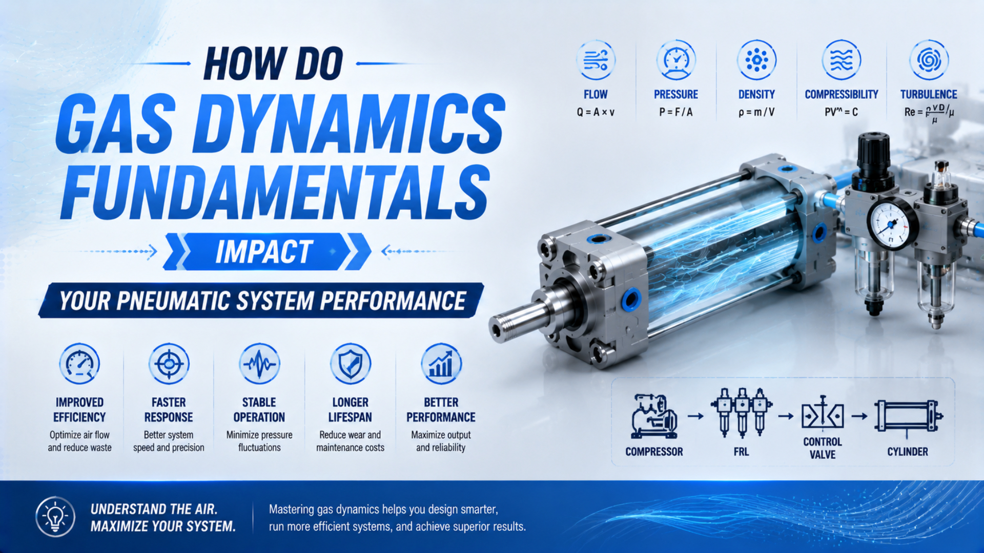
Gas dynamics is the study of how gas pressure, density, temperature, and velocity change while the gas moves or occupies a changing volume. In a pneumatic machine, those changes control cylinder speed, available force, response delay, air consumption, exhaust noise, and repeatability. A regulator pressure setting alone can’t predict any of them.
The practical question isn’t whether air is compressible. It is. The useful question is where compressibility matters in your circuit and which measurement exposes the limiting process. For most industrial machines, start with absolute pressure, temperature, mass flow, effective conductance, tube and chamber volume, and the pressure traces at the actuator.
Key Takeaways
- For air with a heat-capacity ratio near 1.4, ideal nozzle flow reaches its critical condition when downstream static pressure is about 0.528 of upstream stagnation pressure (NASA Glenn).
- Pressure supports force, while mass flow and system volume govern how fast useful chamber pressure develops.
- Measure dynamic pressure at the actuator before increasing plant pressure or replacing a cylinder.
How Do Gas Properties Become Machine Performance?
NIST’s primary gas-flow standards determine accumulated mass from measured pressure, volume, temperature, and an equation of state. Those same 4 quantities form a useful engineering map for a pneumatic machine: pressure and temperature set density, volume stores mass, and changing mass produces the pressure response that drives an actuator (NIST).
For dry air treated as an ideal gas:
Here, is air mass in kilograms, is absolute pressure in pascals, is contained volume in cubic metres, is the specific gas constant for air in joules per kilogram-kelvin, and is absolute temperature in kelvins. Use this equation as a state relation, not as a complete cylinder-motion model.
The relation explains several workshop observations. Increasing chamber volume requires more air mass to reach the same pressure. Warmer air is less dense at the same absolute pressure. A pressure gauge can show an acceptable static value while a valve, fitting, or long tube prevents mass from entering fast enough during motion.
Force and speed therefore come from different parts of the same process. Chamber pressure acting on piston area creates theoretical force. Flow into that changing chamber determines how quickly pressure can be maintained as the piston moves. Exhaust-side pressure subtracts from the useful pressure difference and can slow motion even when the supply gauge looks normal.
Mach number is useful at a local restriction, but it isn’t a master performance setting for the whole machine:
Here, is Mach number, is local gas velocity, and is the local speed of sound. NASA defines the speed of sound for an ideal gas as:
In this expression, is the ratio of specific heats, is the specific gas constant, and is absolute temperature. Local velocity can reach sonic conditions inside a small valve passage while flow in the connected tube remains subsonic. That distinction prevents a common error: assigning one Mach number to an entire pneumatic circuit.
In our experience, the most useful system boundary is often not “the cylinder.” Draw a boundary from the machine inlet through the valve and tubing to one cylinder chamber. Then treat the opposite chamber and its exhaust path as a second flow path. This exposes whether supply filling, exhaust back pressure, or mechanical load is controlling the motion.
Pressure and Flow Must Be Evaluated Together
ISO 6358-1 defines a steady-state method for characterizing pneumatic components with fixed or variable internal flow paths, but it specifically excludes energy-exchanging devices such as cylinders and accumulators. That 1 boundary matters: a valve’s catalog conductance can support system analysis, yet it doesn’t predict a moving cylinder by itself (ISO).
Pressure is energy potential per unit volume, not proof of available flow. If a machine is idle, pressure can equalize across an undersized line. When the valve opens, the demand rises quickly and the restriction reveals itself as a pressure difference. A single regulator gauge may miss the event because it is too far upstream, too slow, or both.
Flow also needs a declared reference. Standard litres per minute and SCFM describe equivalent flow at specified reference conditions. Actual volumetric flow inside a pressurized tube is smaller because the gas is denser. Don’t compare an unnamed “L/min” value from one catalog with a standard-flow value from another.
For a component chain, the smallest port isn’t automatically the only bottleneck. Effective conductance is distributed across filters, regulators, valve galleries, manifolds, fittings, tubing, meter-out controls, quick-exhaust valves, and silencers. ISO 6358-3 provides a method for estimating the overall steady-state flow characteristic of systems assembled from components and piping, including both subsonic and choked regimes (ISO).
This leads to a better selection sequence:
- Define the actuator load, target stroke, allowed stroke time, and required end pressures.
- Estimate the required chamber flow over the motion, including tube and clearance volume.
- Check supply and exhaust paths separately.
- Compare component data at the expected upstream and downstream absolute pressures.
- Confirm the result with dynamic pressure measurements at the machine.
If line losses are uncertain, use the Compressed Air Pressure Drop Calculator as a first-pass screen. It can’t replace valve conductance data or a pressure trace, but it can show whether tube length and inside diameter deserve attention before the regulator setting is raised.
When Does Choked Flow Limit Pneumatic Performance?
NASA’s ideal-gas relation places the maximum mass-flow condition at Mach 1 in the controlling throat. For air approximated with , the critical downstream-static to upstream-stagnation absolute-pressure ratio is about 0.528. Below that ratio, reducing downstream pressure further doesn’t increase the ideal throat mass flow (NASA Glenn).
The ideal critical ratio is:
Here, is the critical ratio of downstream static pressure to upstream stagnation pressure, with both expressed on an absolute scale. The term is the gas heat-capacity ratio. The relationship assumes an ideal gas and an isentropic restriction. Real valves are represented more usefully by tested conductance and critical-ratio data where available.
Choked flow is the condition in which a controlling throat reaches its maximum mass flow for the current upstream state and effective area. It is local. Choking may occur at a spool opening, seat, fitting, speed controller, silencer, or quick-exhaust passage. The tube immediately downstream does not have to remain sonic.
Nor does choking make the mass flow independent of everything downstream forever. A changing chamber pressure can move the operating point out of the choked region during the same stroke.
Upstream conditions still matter. Choked mass flow varies with effective throat area, upstream stagnation pressure, upstream stagnation temperature, gas constant, and heat-capacity ratio. That is why two circuits with the same nominal pressure ratio can deliver different mass flow.
What should you do with this in practice? If the chamber-pressure trace rises slowly while a large pressure difference exists across one component, check that component’s conductance and pressure-ratio data. The Air Orifice Flow Calculator can illustrate the pressure-ratio boundary for a simple opening, but use manufacturer data for a real valve assembly.
For a deeper treatment of the critical ratio and troubleshooting sequence, see what causes choked flow in pneumatic systems. The separate article on sonic conductance and critical pressure ratio explains how ISO-style component parameters differ from a nominal port size.
In our experience, a restriction can be correctly sized for steady flow and still produce an unacceptable stroke. Steady conductance answers how much mass can pass under defined pressure conditions. The moving application adds changing chamber volume, load-dependent pressure, valve timing, exhaust pressure, friction, and heat transfer. Both questions must be answered.
Volume and Heat Transfer Change Dynamic Response
NIST uses pressure-volume-temperature-time and rate-of-rise standards to determine gas mass flow, including collection vessels as small as 0.3 L and 2.5 L in its low-flow systems. The method highlights a general rule: pressure rise in a known volume can’t be interpreted accurately without time and gas temperature (NIST).
In a pneumatic machine, the controlled volume includes more than the nominal cylinder displacement. Add the tube bore and length, fitting cavities, valve-to-port galleries, end clearance, cushion recesses, manifolds, and any auxiliary reservoir connected during the event. A long large-bore tube may reduce frictional pressure drop yet add enough volume to delay pressure build-up. Bigger is not always faster.
The process is transient. As air enters a chamber, mass increases, the piston changes volume, gas temperature can rise through compression, and heat moves to the metal walls. During exhaust, rapid expansion and blowdown may cool the gas and nearby hardware. A simple isothermal or isentropic equation is therefore a limiting model, not a universal temperature prediction.
Valve-connected cylinder chambers are open control volumes while they flow. Applying a closed-mass relation across an entire powered stroke ignores the air entering and leaving. If you need a thermodynamic approximation, state the boundary, interval, valve state, leakage assumption, and heat-transfer assumption. Otherwise, use measured pressure and position traces with a mass-flow model.
If the problem is stopped-axis compliance, stick-slip, or closed-loop positioning rather than circuit flow capacity, see how air compressibility affects pneumatic cylinder control. That analysis treats pneumatic stiffness and controller limits instead of repeating the supply-path calculations used here.
Condensation and icing need an equally careful boundary. A local temperature drop can bring air below its dew point, especially when moisture removal is inadequate, but the outcome depends on inlet moisture, pressure, expansion rate, metal temperature, duty cycle, and ambient heat transfer. There is no defensible universal “temperature drop per valve.”
Which Restrictions Should You Check First?
The U.S. Department of Energy’s compressed-air sourcebook recommends keeping total loss from receiver output to point of use well below 10% of compressor discharge pressure in a properly designed system. It also identifies hoses, tubes, disconnects, filters, regulators, and lubricators as common point-of-use pressure-drop locations (U.S. DOE).
Start at the symptom, not at the compressor. If one cylinder is slow while adjacent equipment is stable, inspect the local branch, machine inlet, valve, meter-out control, tubing, fittings, port adapters, and exhaust silencer. If several machines sag together, move upstream toward the header, dryer, filter bank, receiver, or compressor control.
Supply and exhaust restrictions produce different traces:
| Observation during motion | Likely gas-dynamic interpretation | First checks |
|---|---|---|
| Machine inlet pressure collapses | Upstream branch or plant supply cannot support peak mass flow | Header pressure, branch ID, filter differential, local storage |
| Inlet remains steady but supply chamber fills slowly | Restriction lies between inlet sensor and chamber | Regulator, valve conductance, fittings, tube ID and length |
| Supply chamber reaches pressure but motion stays slow | Load, friction, cushioning, or exhaust back pressure may dominate | Opposite-chamber pressure, alignment, speed controls, silencer |
| Speed changes strongly with cycle rate | Heat, depleted local storage, regulator recovery, or repeated filling may be involved | Temperature, receiver pressure, duty cycle, regulator response |
| Sharp pressure oscillations follow switching | A transient wave or valve event may be present | High-speed pressure trace, tube length, valve timing, end conditions |
Port labels can mislead. A valve sold with a large threaded connection may still contain a smaller internal passage, and a small elbow or silencer can dominate the exhaust path. Compare tested flow characteristics, not only thread size.
Tubing layout also changes both resistance and stored volume. Keep runs direct, avoid unnecessary coils, respect bend radius, and size the inside diameter for the peak event. The detailed routing checklist is covered in how to route pneumatic tubing in automated machinery. For metering choices, use the pneumatic flow-control valve sizing guide.
A Practical Measurement Workflow
NIST’s PVTt name identifies 4 measured quantities: pressure, volume, temperature, and time. A machine diagnosis should add valve command, actuator position, and both chamber pressures. Synchronizing those signals separates supply starvation, exhaust restriction, load breakaway, thermal drift, and control timing far better than a single static gauge (NIST).
Use a repeatable operating condition. Record supply temperature, ambient temperature, machine inlet pressure, cycle rate, payload, regulator setting, valve command, actuator position, and chamber pressure. If possible, measure the pressure immediately upstream and downstream of the suspected restriction. A pressure difference that appears only during flow is valuable evidence.
Follow this sequence:
- Verify units and references. Convert gauge pressure to absolute pressure before using gas equations or pressure ratios. The distinction is explained in how absolute pressure affects pneumatic performance.
- Capture a baseline trace. Log several warm, stable cycles rather than one convenient stroke.
- Locate the pressure loss. Move one sensor boundary at a time from the machine inlet toward the cylinder.
- Separate extend and retract paths. A double-acting cylinder uses different piston areas and may have different supply and exhaust restrictions.
- Change one variable. Test a larger tube, a clean silencer, a different valve, a lower cycle rate, or a temporary local receiver without combining modifications.
- Repeat under the worst load. Confirm both performance and component pressure ratings.
What if the waveform contains a fast spike rather than a sustained pressure difference? Use a sensor and acquisition rate fast enough for the event, then examine valve timing, reflections, and abrupt flow interruption. The air-hammer analysis guide treats those transient waves separately from steady pressure drop.
The decisive measurement is often the pressure difference across a component during the short interval when speed is lost. Average flow and static pressure can both look acceptable because they erase the peak event. Align the command, position, and pressure traces on the same time axis before changing hardware.
How Should You Apply Gas Dynamics During Design?
ISO 6358 separates component testing from system calculation across 3 published parts, while Part 1 excludes cylinders and accumulators from its steady-state component method. The design consequence is direct: use component conductance data for flow paths, then evaluate changing volume, load, chamber pressure, and timing at the machine level (ISO).
Use this checklist before releasing a pneumatic circuit:
- Define minimum force from the lowest acceptable chamber pressure, not only the regulator setpoint.
- Specify the target stroke time and duty cycle in both directions.
- Use absolute pressure and temperature for gas equations.
- Declare whether flow values are standard, normal, free-air, mass, or actual volumetric flow.
- Obtain tested conductance or comparable flow data for valves, regulators, fittings, controls, and silencers.
- Add tube and clearance volumes to the driven chamber volume.
- Check the supply and exhaust pressure ratios across the full stroke.
- Review local choking at restrictions without treating it as a circuit-wide Mach condition.
- Include ambient temperature, moisture control, and expected warm-up state.
- Provide pressure test points near the machine inlet and actuator.
- Validate the final circuit under minimum supply, maximum load, and maximum cycle rate.
Don’t use a higher plant pressure to hide a local restriction. That may restore one actuator while increasing leakage, unregulated demand, and stress elsewhere. The DOE sourcebook recommends reducing pressure drops and using strategic storage before adding compressor capacity or increasing system pressure (U.S. DOE).
Gas dynamics becomes manageable when each model has a declared boundary. Use ideal-gas relations for state changes, ISO-style conductance for tested component flow, pressure-ratio analysis for local choking, and synchronized measurements for the moving machine. That combination is far more reliable than assigning the entire circuit a Mach regime.
For a technical circuit review, send the valve and actuator model numbers, tubing inside diameter and length, supply and chamber pressure traces, load, stroke, and target cycle time through the technical contact page. Those inputs make it possible to identify the correct calculation boundary before hardware is changed.
Gas Dynamics FAQs: What Should Pneumatic Engineers Check?
NASA identifies Mach 1 as the maximum ideal mass-flow condition at a controlling throat, while ISO 6358 distinguishes steady component characterization from full system behavior. These 2 boundaries resolve many recurring questions about pressure settings, choked valves, altitude, temperature change, and slow cylinder response (NASA Glenn; ISO).
Does a higher regulator pressure always make a pneumatic cylinder faster?
No. Higher upstream absolute pressure can increase available mass flow and force, but speed may still be limited by valve conductance, tubing, fittings, meter-out controls, exhaust back pressure, load, or cushioning. Measure pressure at both cylinder chambers during motion before raising the regulator or plant header pressure.
Does choked flow make pneumatic flow independent of downstream pressure?
Only within a defined range. Once the downstream-static to upstream-stagnation absolute-pressure ratio falls below the critical value, further lowering downstream pressure doesn’t increase ideal throat mass flow. Upstream pressure, upstream temperature, effective area, gas properties, and the restriction’s tested conductance still determine the available flow.
Does altitude change the critical pressure ratio?
Not directly for the same ideal gas and heat-capacity ratio. Altitude changes atmospheric absolute pressure, compressor inlet conditions, gauge-to-absolute conversions, and the exhaust boundary. Those changes can move a component into or out of choking, even though the ideal critical ratio itself remains tied primarily to the gas property .
Why can a cylinder be slow when the static pressure is correct?
Static pressure can recover while the actuator is idle. During motion, an undersized valve, tube, fitting, filter, regulator, or silencer may create a large pressure difference and restrict mass flow. Use synchronized machine-inlet, chamber-pressure, valve-command, and position traces to capture the short interval when speed is lost.
Can gas-dynamics equations predict the exact cylinder stroke time?
Not from one equation. Stroke time depends on changing chamber volumes, supply and exhaust mass flow, both chamber pressures, load, friction, valve timing, cushioning, leakage, and heat transfer. A fill-time estimate can screen the volume-flow relationship, but final acceptance needs a component model or measurements from the assembled circuit.
Sources and technical references
- ISO 6358-1:2013, steady-state flow characteristics of pneumatic components
- ISO 6358-3:2014, calculating steady-state characteristics of systems
- NASA Glenn, Mass Flow Choking
- NASA Glenn, Isentropic Flow Equations
- NASA Glenn, Speed of Sound Equation
- NIST, Gas Flow Standards
- U.S. Department of Energy, Improving Compressed Air System Performance