

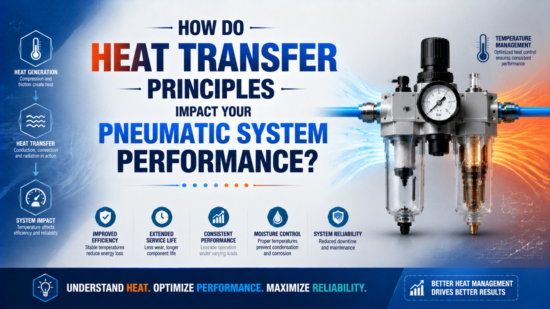
Heat transfer in a pneumatic system is the movement of thermal energy within the gas and hardware or across the system boundary. Boundary choice matters. Heat affects gas density, seal and lubricant conditions, clearances, sensor limits, and the rate at which a component reaches thermal equilibrium. The US Department of Energy identifies three surface-transfer modes: conduction, convection, and radiation (DOE, retrieved 2026).
A warm cylinder is therefore a symptom, not a diagnosis. It may be rejecting normal compression or friction heat, absorbing heat from a machine frame, or approaching a model-specific limit. The right question is not simply “How hot is it?” It is “Where is energy entering, where can it leave, and which rated component sets the limit?”
Key Takeaways
- Conduction, convection, and radiation describe surface heat paths, not a complete powered-cylinder cycle.
- One SMC cylinder manual specifies 5-60°C, but every model and accessory must be checked separately.
- Surface temperature does not equal chamber-gas or seal-contact temperature.
- Cooling hardware should follow root-cause checks, not replace them.
Temperatures That Define the Thermal Boundary
One SMC stainless-steel cylinder manual specifies an ambient and fluid temperature range of 5-60°C and warns against operation outside the stated temperature, pressure, or kinetic-energy limits. That is a product-family requirement, not a universal pneumatic limit (SMC, retrieved 2026).
A useful thermal review separates at least five temperatures:
- Supply-air temperature at the valve inlet, after the air has passed through upstream treatment equipment and distribution piping.
- Chamber-gas temperature during filling, compression, expansion, dwell, and exhaust.
- Component surface temperature at the barrel, end cap, valve body, coil, guide, or manifold. This visible boundary usually responds more slowly than chamber gas.
- Local ambient temperature around the installed component.
- Neighbouring structure temperature at brackets, guards, machine frames, ovens, tooling, or process equipment.
These values do not move together. Chamber air can heat during compression and cool during expansion while the cylinder wall changes much more slowly. A hot bracket can conduct energy into a cylinder even when its internal friction is normal. Conversely, a cool visible surface does not prove that a hidden seal contact or solenoid winding is within its rating.
For field comparisons, record temperature rise above the local ambient:
is the surface temperature rise in K or °C. Its inputs are the measured surface value and local air temperature , taken at the same operating state. Units stay consistent: temperature differences have the same numerical value in K and °C.
Use the exact datasheets for the cylinder, seals, grease, valve, coil, switch, cable, fitting, and tubing. A special high-temperature actuator does not automatically raise the rating of its standard sensor or nearby valve.
Heat Sources and Heat-Rejection Paths
DOE guidance separates conduction, convection, and radiation as three mechanisms, but a pneumatic component can experience all three. Their directions depend on local temperature differences. Heat may leave through a mounting bracket while entering the same cylinder by radiation from a nearby oven (DOE, retrieved 2026).
Common heat inputs include:
- Mass flow and gas compression. Air entering a chamber carries enthalpy. Pressure, temperature, and volume then change during the stroke, with the inlet state and valve flow influencing the transient result.
- Seal and guide friction. Sliding contacts generate heat.
- Cushioning and impact. End-of-stroke kinetic energy must be absorbed by an air cushion, elastomer bumper, shock absorber, or machine structure.
- Valve-coil electrical loss. An energized solenoid warms nearby hardware.
- Throttling and exhaust restriction. A restriction changes pressure and temperature while also affecting speed, backpressure, and cycle time.
- External process heat. Furnaces, welding, hot tooling, washdown water, sunlight, and machine frames can dominate the component’s own heat generation.
Cooling can occur through the same boundaries. Expansion and exhaust may produce local cooling. The SMC manual also warns that temperature drops caused by piping or operating conditions can create condensation, which may degrade or wash away grease and shorten service life. Heat management must therefore consider both overheating and unwanted cooling.
For detailed cycle-rate and impact analysis, use the short-stroke thermal buildup guide and the pneumatic cushion energy guide. This article stays at the system heat-path level.
Which Heat Transfer Equation Should You Use?
NASA gives the Stefan-Boltzmann constant as for radiation heat loss. The value is fixed. Conductivity, contact resistance, convection coefficient, emissivity, area, temperatures, and geometry are installation inputs, so choose an equation only after defining the boundary (NASA, 2012).
Conduction through a solid path
For a one-dimensional solid with constant properties and cross-section:
is the heat-transfer rate in W. Thermal conductivity is measured in W/(m·K), while is the area normal to heat flow in m². The path length is in m. The temperature difference is expressed in K.
Use this relationship for a defined barrel wall, bracket, plate, or other known heat path. A catalog conductivity cannot describe an entire bolted assembly because paint, oxide, fastener preload, gaps, surface flatness, and real contact area alter the joint. The interface may control.
Thermal resistance is often easier for a multi-part path:
Series resistances add. Parallel paths split heat. A bracket that conducts heat away in one installation may conduct process heat into the actuator in another, so “higher conductivity” is not automatically better.
Convection between a surface and air
For a surface at a reasonably uniform temperature:
is the convection coefficient in W/(m²·K), and is exposed area. Surface temperature is . Local bulk-air temperature, written as , must represent the air outside the immediate thermal boundary layer. The sign changes when that air is hotter than the surface.
The difficult input is . It depends on air properties, orientation, geometry, velocity, turbulence, obstructions, and whether flow is natural or forced. A generic coefficient can support a screening calculation, but a fan selection or thermal guarantee needs a validated correlation, test, or simulation for the installed geometry.
Compressed-air jets are rarely a sensible default cooler. They add air demand, noise, contamination movement, and possible condensation while masking the original heat source. Avoid that trade. First confirm that airflow is the limiting heat path.
Radiation between a surface and its surroundings
For a small gray surface exchanging radiation with large surroundings:
is surface emissivity. NASA’s Stefan-Boltzmann constant is , while is the radiating area presented to the surroundings. Both temperatures must be absolute values in K. Real enclosures may also require view factors and opposing-surface properties.
Radiation cannot be calculated correctly with °C inside the fourth-power term. Emissivity also cannot be selected from a generic material name without considering the condition of the actual installed surface. Inspect it. Oxidation, paint, contamination, wavelength, temperature, and viewing geometry all affect the input.
A surface balance is not a chamber model
A surface heat balance is an accounting of thermal energy entering, leaving, or accumulating inside a defined hardware boundary. The three external rates can be combined as a surface heat-rejection estimate:
This equation does not describe an entire powered cylinder stroke. A valve-connected chamber exchanges mass while its volume changes. The first law for a control volume includes mass flow, heat and work. Use the separate adiabatic versus isothermal cylinder guide for that thermodynamic boundary.
The practical distinction is simple: surface equations estimate how fast a defined component boundary can exchange heat. Chamber equations estimate how gas state changes while air enters, leaves, compresses, expands, and moves a load. Mixing the two can produce a precise-looking answer to the wrong problem.
Worked Example: What Can a Surface Heat Balance Tell You?
NASA gives for thermal radiation. Using that constant with stated assumptions lets an engineer compare heat paths without presenting the result as a universal cylinder capacity (NASA, 2012).
Assume a component has:
- Exposed area .
- Surface temperature , equal to 60°C.
- Ambient and radiative surroundings at , equal to 25°C.
- Assumed convection coefficient .
- Assumed emissivity .
- A measured mounting-path resistance to a bracket at 35°C, obtained from a separate steady-state test of the installed joint.
The screening results are:
| Heat path | Calculation | Estimated rate |
|---|---|---|
| Convection | 33.6 W | |
| Radiation | 24.0 W | |
| Mount conduction | 8.3 W | |
| Total | Sum of the three paths | 65.9 W |
The calculation says that this assumed boundary could reject about 66 W while holding the stated temperatures. It is a screening result. It does not prove that the real component generates 66 W, that its internal seals are 60°C, or that 60°C is acceptable. Those conclusions require measured inputs, a model-specific limit, and a steady condition.
Try a sensitivity check before changing hardware. Recalculate with the measured airflow, surface finish, mounting temperature, and exposed area. If the answer changes mainly with , airflow may deserve further study. If it changes mainly with the bracket temperature, moving or insulating the conductive path may matter more than adding a fan.
How Does Heat Transfer Change Pneumatic Performance?
The same SMC manual that lists a 5-60°C operating range also warns that moisture condensation can degrade or wash away grease. Temperature affects performance through material limits, air state, lubrication and clearance, but it does not supply one universal life multiplier or efficiency penalty (SMC, retrieved 2026).
| Observation | Heat-transfer interpretation | What must be checked before acting |
|---|---|---|
| Cylinder surface warms and reaches a repeatable plateau | Heat generation and rejection may have reached equilibrium | Exact ratings, load, pressure, speed, cycle definition and baseline |
| Gland or guide is hotter than the barrel | Local friction, side load, contamination or poor heat spreading may be involved | Alignment, guide reactions, lubrication, leakage and contact-temperature confirmation |
| Valve body is warm near the coil | Electrical heating may be entering the manifold | Coil voltage, duty rating, ambient temperature and valve manual |
| Exhaust port or tubing becomes cold | Expansion or high flow may be cooling the local surface | Dew point, drainage, icing, restriction and exhaust capacity |
| Entire actuator tracks a hot machine frame | Conduction or radiation from the process may dominate | Bracket temperature, shielding, view to hot surfaces and installation layout |
| Temperature rises after cushion adjustment | More end energy or exhaust restriction may be dissipated locally | Moving mass, speed, cushion setting, backpressure and allowable kinetic energy |
Pressure and temperature also influence air density. Density is only one input. A hot supply volume contains less mass than the same volume at the same absolute pressure when colder. Yet a production cylinder’s force and timing depend on both chamber pressures and valve flow. Restrictions, friction, load and the control strategy also matter. Do not turn one temperature reading into an unsupported force or energy correction.
If temperature changes coincide with unstable point-of-use pressure, use the pressure fluctuation diagnostic guide. If the question is chamber volume and wasted air, continue with the dead-volume efficiency guide.
Which Thermal Control Measure Should Come First?
ISO 4414:2010 addresses safety, reliable operation, maintenance and energy efficiency for pneumatic systems and their components. Its scope supports a system-level sequence. Identify the hazard and operating condition first, verify component compatibility, remove the cause and then validate the modification (ISO, confirmed 2021).
Apply corrective measures in this order:
- Reduce avoidable heat generation. Correct side load, binding, excessive speed, repeated impact, exhaust restriction, leakage, incorrect voltage, and unsuitable duty before adding hardware that may hide the symptom without lowering the original loss.
- Reduce external heat input. Relocate the component, add a shield, change the bracket path, or isolate it from hot tooling when the process is the source.
- Restore intended heat rejection. Remove blocked ventilation, accumulated lint, covers, or deposits only when doing so is compatible with the environment and manufacturer instructions.
- Evaluate engineered cooling. A fan, duct, heat spreader, or heat sink needs verified airflow, geometry, cleanliness, power, noise and maintenance requirements.
- Select a rated product. Specify a compatible assembly.
Do not put thermal paste into a cylinder interface, remove a coating, drill fins into a body, or change fastener torque unless the component manufacturer approves the modification. These actions can change fit, corrosion protection, sealing, cleanliness and structural load paths.
For applications already outside standard ratings, use the high-temperature cylinder selection guide. For repeated-operation testing and sensor placement, use the high-cycle cylinder thermal analysis guide.
What Should Be Recorded Before a Thermal Design Change?
SMC’s example manual specifies at least four thermal-adjacent limits in one table: ambient and fluid temperature, pressure, piston speed, and allowable kinetic energy. A defensible change record must preserve the complete operating recipe because temperature alone cannot show whether the component was used inside those other limits (SMC, retrieved 2026).
Record:
- Manufacturer, series, complete part number, installed options, revision of the datasheet, and the lowest temperature rating among every sensor, cable, seal, grease, valve, tube and fitting in the assembly.
- Cylinder bore, stroke, mounting and guided-load arrangement.
- Valve, coil, tubing, fittings, silencers and flow-control configuration.
- Valve-inlet state.
- Both chamber pressures when transient behaviour matters.
- Load, speed, dwell, cycle definition, cycle rate and duty period.
- Local ambient, nearby hot surfaces and airflow state.
- Repeatable surface measurement points and sensor method.
- Stable temperature, time to plateau, cooldown behaviour and stop criteria.
- Leakage, alignment, lubrication, drainage, contamination and maintenance findings.
Infrared imaging can locate a useful comparison point, but it needs its own controls. NIST determines sample temperature using emissivity-related and radiance measurements against blackbody references, illustrating why emissivity cannot be treated as an automatic camera setting (NIST, updated 2025). Use the cylinder-seal thermography guide for the full measurement workflow.
In our experience reviewing replacement requests, the most useful thermal request is rarely “send a cooler cylinder.” A record such as “the mounting bracket remains 18°C hotter than local air while the cylinder is idle” immediately points toward an external conductive path. “The cylinder gets hot” leaves the engineering boundary undefined.
Pneumatic Heat Transfer FAQs
SMC lists 5-60°C for one stainless-steel cylinder family and offers other products with different temperature capabilities. These five FAQs therefore use heat-transfer equations as diagnostic tools while keeping acceptance limits tied to the complete part number and installed accessories (SMC, retrieved 2026).
Does a hot pneumatic cylinder always mean energy is being wasted?
No. A warm surface shows that energy reached that location and is being stored or transferred. It does not identify the source or quantify system efficiency. Compare the temperature with ambient, duty, pressure, load and the exact rating, then check friction, impact, leakage, restrictions and external heat before assigning an energy-loss cause.
Can I use a polytropic equation for a complete powered cylinder stroke?
Not as a universal model. A relation such as can describe an approximately fixed mass over a defined interval. During a powered stroke, air normally enters one chamber and leaves the other while both volumes change. Use mass and energy balances, absolute pressure and temperature, valve flow and wall heat transfer.
Should I add a fan when a pneumatic component runs hot?
Only after confirming that external convection is the limiting path. A fan cannot correct side load, seal damage, cushion impact, hot supply air or an overheated mounting structure. If testing supports forced convection, verify airflow, contamination control, power, noise, maintenance access and temperature margin under the full duty cycle.
Can an infrared camera measure the internal seal temperature?
No. It estimates the temperature of a visible surface from detected radiation and user-supplied corrections. Emissivity and reflected surroundings can change the result. So can viewing angle and spot size. Use thermal imaging to locate repeatable surface patterns, then corroborate them with contact measurements and mechanical or pneumatic evidence.
When should I specify a high-temperature pneumatic cylinder?
Specify one when measured ambient or fluid temperature, external radiation, conducted heat or duty-cycle heating exceeds the standard assembly’s rating after avoidable faults are removed. Confirm the cylinder and seal limits together. Then check grease, sensor, cable, valve, tube and fitting ratings. A high-temperature seal alone does not qualify the complete installation.
Sources and technical references
-
US Department of Energy, Thermodynamics, Heat Transfer, and Fluid Flow, Volume 2, retrieved July 27, 2026.
-
MIT Unified Engineering, First Law for a Control Volume, retrieved July 27, 2026.
-
NASA, Performance Testing of a Non-Nuclear Fuel Element in a Hot Hydrogen Stream, 2012, retrieved July 27, 2026.
-
NIST, System for Infrared Spectral Emittance of Materials, updated 2025, retrieved July 27, 2026.
-
SMC, Stainless Steel Cylinder Operation Manual, DOC1054735, retrieved July 27, 2026.
-
SMC, ISO Compact Cylinder C55/CD55 Product Information, retrieved July 27, 2026.
-
ISO 4414:2010, Pneumatic Fluid Power, General Rules and Safety Requirements, confirmed 2021.