

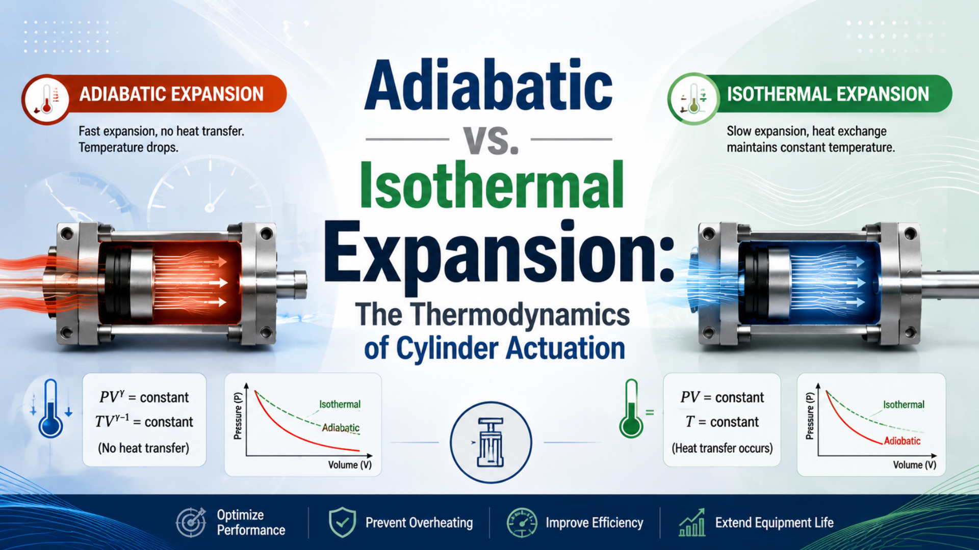
Adiabatic and isothermal expansion are useful limits, not competing labels for an entire pneumatic-cylinder stroke. The adiabatic vs. isothermal expansion comparison becomes useful only after the system boundary is defined. A working cylinder is usually open and transient: air enters one chamber, air leaves the other, the piston changes both volumes, and heat crosses the walls.
A 2017 experiment used a 50 mm bore, 20 mm rod, and 200 mm stroke cylinder. Its two chambers behaved differently. One air charge heated by 23 K during compression, while the expanding side cooled by 17 K; neither result creates a universal correction factor for other cylinders (Hassan, Ghanim, and Hamandy, 2017).
Key Takeaways
- One test measured a 23 K rise and a 17 K drop inside cylinder chambers.
- Use absolute pressure and temperature in gas-law calculations.
- Treat isothermal and reversible adiabatic paths as model limits.
- Calculate force from both chamber pressures, areas, friction, and load.
The Correct System Boundary Comes First
A 2006 actuator-model study found that reduced-order methods can omit temperature dynamics, inlet-air mixing, and explicit wall heat transfer. Boundary choice changes the answer. A sealed chamber may be modeled as a closed mass, while a powered cylinder chamber exchanges mass as its volume changes (Carneiro and Almeida, 2006).
Start with the ideal-gas state equation:
In this equation, is absolute pressure, is chamber volume, is air mass, is the specific gas constant, and is absolute temperature. For air, NASA reports approximately 0.286 kJ/(kg·K) for (NASA Glenn Research Center, retrieved July 22, 2026).
Pressure over time also depends on mass entering and leaving, piston motion, and heat transfer, so a cylinder chamber needs a control-volume energy balance:
is the chamber air’s internal energy, is heat transfer into the air, is mass-flow rate, is specific enthalpy, and is boundary power delivered through piston motion. The signs assume positive piston work leaves the chamber. A complete model also needs leakage and may need spatial temperature gradients.
Apply each label to a defined gas mass and time interval, not to the cylinder name. Air trapped behind a closed valve, supply air crossing a restriction, and exhaust accelerating through a valve are different control problems; calling all three “adiabatic expansion” hides the term that may control the result.
Which Thermodynamic Stages Occur During One Cylinder Cycle?
The 2017 cylinder experiment measured pressure, piston displacement, and temperature simultaneously, finding a 23 K temperature rise in one chamber during compression and a 17 K drop in the expanding chamber. A cylinder cycle should therefore be divided by valve state and piston motion before selecting any process law (Hassan et al., 2017).
| Cycle stage | Mass boundary | Volume change | Dominant questions | Useful first model |
|---|---|---|---|---|
| Initial filling | Air enters | Small or zero before breakaway | How fast does pressure reach breakaway force? | Transient open system |
| Acceleration and stroke | Air enters one side and exits the other | Both chambers change | What sets pressure, force, speed, and temperature? | Two open chambers plus piston dynamics |
| Cushioning | Flow paths become restricted | Rapid local change near end cap | How high are back pressure and deceleration? | Transient chamber and restriction model |
| End-position hold | Valves may close or continue supplying | Nearly fixed | How do leakage and heat recovery change pressure? | Fixed-volume or leakage model |
| Exhaust and reset | Air leaves through valve and silencer | Depends on piston motion | Where do pressure drop and cooling occur? | Open blowdown and compressible-flow model |
During initial filling, the piston may remain still while supply air raises the driving-chamber pressure. The chamber is close to constant volume, but it is not a closed mass. What changes at breakaway? Once pressure force exceeds the opposing chamber force, friction, and external load, the piston moves and converts part of the incoming pneumatic energy into mechanical work. During motion, the supply chamber grows while the exhaust chamber shrinks, and both sides exchange mass through restrictions. Valve conductance, tubing volume, port geometry, supply droop, exhaust back pressure, friction, and load determine the pressure histories. The related guide to air compressibility and cylinder control explains how those histories also change stiffness and settling.
At the end of stroke, the boundary changes again. A trapped chamber can approach a closed-system model after its valve path closes, but leakage and thermal recovery slowly move its state. This is why a model that fits the moving phase may fail during a long hold.
What Do Isothermal, Adiabatic, and Polytropic Models Actually Mean?
NIST defines one standard atmosphere as exactly 101,325 Pa, equal to 14.6959 psi. Gas-law pressure ratios must use absolute pressure, not gauge pressure, because the thermodynamic state is measured from vacuum and the choice affects pressure, temperature, and boundary work (NIST Pressure and Gas Flow Unit Conversions, updated 2025).
These three models impose different constraints on the same ideal gas.
Isothermal expansion is a fixed-temperature path for a defined gas mass. Boyle’s law gives:
is constant for the selected gas mass. As volume increases, pressure decreases. Isothermal does not mean constant pressure or constant cylinder force. It means that heat transfer offsets the internal-energy change that would otherwise accompany expansion or compression.
Reversible adiabatic expansion is a no-heat-transfer, no-entropy-generation path for a defined gas mass. For a calorically perfect gas:
is the ratio of specific heats. Near ordinary pneumatic temperatures, is a common dry-air approximation. Adiabatic means no heat crosses the selected boundary. Isentropic adds reversibility, so friction, turbulence, mixing, and finite pressure drops make a real process differ from the reversible equation. MIT’s ideal-gas lecture treats isothermal, reversible adiabatic, and free expansion as distinct paths (MIT OpenCourseWare, 2021).
Polytropic expansion is a compact empirical approximation represented by:
is a fitted exponent for a defined process, geometry, time range, and operating condition. Setting reproduces the isothermal relation. Setting reproduces the reversible adiabatic relation. A value between them can approximate some closed-chamber tests, but it does not automatically include valve flow, leakage, friction, or changing air mass.
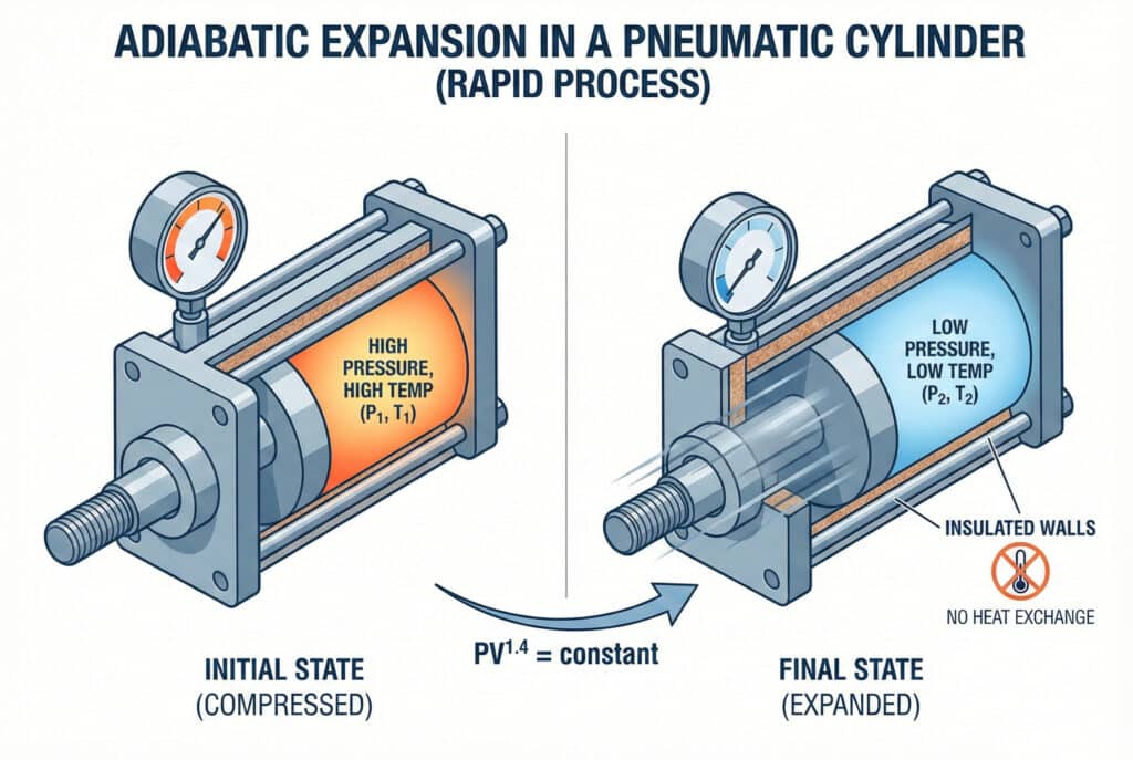
This reversible adiabatic picture is a closed-mass limit, not an insulated working cylinder exchanging air through a valve.
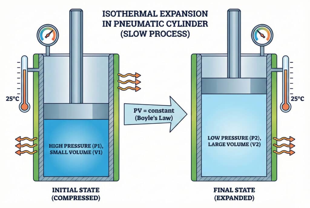
This isothermal picture is a closed-mass limit in which constant temperature still allows pressure to fall as volume increases.
Worked Closed-System Benchmark
NASA gives for air, while its isentropic relations connect pressure, density, and temperature for a calorically perfect gas. The next calculation compares model limits for one fixed gas mass. It does not predict a valve-driven cylinder stroke (NASA, retrieved July 22, 2026).
Assume dry air begins at an absolute pressure of 7 bar, a temperature of 293.15 K, and a volume of 0.25 L. Let it expand to 0.50 L. The volume doubles, so the ratio is .
Start with the isothermal limit:
At a final absolute pressure of 3.50 bar, the ideal boundary work is:
Using SI units gives approximately 121 J.
Now apply the reversible adiabatic limit:
With and final pressure near 2.65 bar absolute, calculate final temperature from:
At approximately 222 K, or -51°C, the ideal boundary work becomes:
The result is approximately 106 J. Because heat enters during expansion, the isothermal path delivers more work between these volume endpoints than the reversible adiabatic path. Yet this benchmark does not rate a powered cylinder: its supply valve adds mass while the opposing chamber creates back pressure.
How Should Engineers Choose a Polytropic Exponent?
The 2006 reduced-order study compared constant-temperature and polytropic assumptions with models that include inlet-air mixing and wall heat transfer. No exponent won universally. That distinction matters in practice. Model complexity should follow the pressure-prediction task, not a value copied from another actuator (Carneiro and Almeida, 2006).
When a chamber is genuinely trapped, estimate from synchronized absolute pressure and volume data over the selected interval:
Both pressures must be absolute, and neither volume may omit end-cap clearance, ports, fittings, tubing, or valve-side dead volume that remains connected. Use data only where mass is effectively constant. If a valve is still supplying, exhausting, or leaking appreciably, the fitted exponent absorbs mass-flow effects and loses its physical meaning. Don’t fit one exponent across a complete cycle. Breakaway, acceleration, mid-stroke motion, cushioning, dwell, and thermal recovery have different boundaries. Repeat the test at the relevant supply pressure, load, speed, stroke position, ambient temperature, and cycle rate, then report sensor locations and sample rate with the fitted value.
A good exponent is local evidence, not a material property of air. A changed value does not mean the air acquired new thermodynamics; the simplified closed-path relation is absorbing dynamics that belong in the mass-flow and heat-transfer terms.
Compare the simple model against a higher-order pressure equation before accepting it for control design. A 1999 dynamic analysis showed that continuity and polytropic models can be replaced by an explicit energy formulation with wall heat conduction and convection from gas entering and leaving double-acting actuator chambers (Pneumatic actuator dynamic analysis, 1999).
What Does the Expansion Model Change in Force, Speed, and Air Use?
CAGI’s 2021 system-design handbook calculates cylinder demand from swept volume, actual stroke, and regulated pressure, and warns that individual devices can differ by more than 10% from approximate figures. Thermodynamic assumptions affect transient pressure and normalized air volume, but they don’t replace the actuator’s mechanical force balance (CAGI, 2021).
For cap-end extension of a single-rod double-acting cylinder:
and are simultaneous gauge pressures referenced to the same ambient pressure, is piston area, is rod-side annular area, and the remaining terms oppose extension. This equation gives the instantaneous net force available for acceleration. The pneumatic cylinder force guide explains the area and pressure terms in detail.
Temperature affects force indirectly when it changes chamber pressure, mass flow, seal friction, leakage, or lubricant behavior. If both port pressures are measured, don’t subtract a second generic “adiabatic loss percentage” because that counts part of the same effect twice. What usually limits the stroke? Speed depends on how rapidly mass reaches and leaves both chambers, not only on a chosen exponent. A valve or tube can enter choked flow even when downstream pressure falls further. The guide to choked flow and cylinder speed covers that restriction boundary, while meter-out control explains why exhaust back pressure improves stability but consumes force margin.
Air consumption uses another boundary. Standard or free-air demand converts the mass used per cycle to a declared reference pressure and temperature, not the instantaneous geometric chamber volume. CAGI recommends actual stroke and regulated pressure; the cylinder air-consumption guide adds clearance, cycle rate, and reference-condition checks. For a quick ratio check, the Compression Ratio Calculator verifies absolute pressures but does not calculate heat transfer, chamber temperature, cylinder work, or the correct polytropic exponent.
A Measurement Workflow for Real Cylinder Actuation
ISO 6358-1:2013 defines steady-state flow testing for pneumatic components with compressible fluids, but explicitly excludes components such as cylinders and accumulators that exchange energy with the fluid during measurement. Use valve flow data as one model input, then measure the operating cylinder as a transient system (ISO 6358-1, 2013).
Record synchronized signals whenever the calculation influences sizing, cycle time, safety, or control tuning:
- Valve command and, when available, spool or poppet feedback.
- Supply pressure at the valve inlet during the event.
- Cap-end and rod-end pressure at the cylinder ports.
- Piston position and velocity at the process-relevant datum.
- Load force or a defensible load and friction estimate.
- Chamber or port temperature with sensor response time and mounting method.
- Ambient temperature and time since machine start-up.
- Valve model, tube inside diameter and length, fittings, silencers, and flow-control settings.
- Cycle rate, dwell time, stroke used, cushioning, and end-stop contact.
- Air quality, pressure dew point, lubrication state, and observed condensation or frost.
Place pressure sensors close enough to the ports to capture chamber behavior without mistaking long-tube pressure for chamber pressure. Temperature measurement is harder: a surface thermocouple reads metal, while a fast gas-path probe reads one local gas region and may disturb flow. State exactly what was measured. Next, plot valve command, both port pressures, position, and temperature against one time base. A delay before motion may be pressure buildup against breakaway friction. Falling supply pressure during the stroke suggests a flow or distribution problem, whereas a temperature change after motion stops points toward heat recovery.
Sketch two boundaries on the circuit diagram: one encloses the moving chamber air and crosses the valve flow path. Another encloses the trapped volume after closure. Reusing the same equation for both drawings without changing its mass-flow terms probably solves the wrong problem.
Which Design Rules Follow From the Thermodynamics?
SMC warns that calculated pressure, temperature, and air-quantity results can differ from actual equipment. CAGI adds that approximate air-use figures for individual tools may vary by more than 10% from published estimates. Oversizing isn’t a cure. Model the mechanism, then validate the configured circuit (SMC; CAGI).
- Do not oversize the bore to “beat adiabatic loss.” Select bore from measured or defensible dynamic pressure, load, friction, acceleration, and safety requirements. A larger bore also increases swept volume and flow demand.
- Do not raise plant pressure as a thermal correction. More pressure changes available force and air use, but it doesn’t remove a restrictive valve, long tube, high exhaust back pressure, or poor control tuning.
- Do not insulate a standard cylinder to make it adiabatic. Insulation can reduce heat recovery and change seal and lubricant temperatures. Follow the manufacturer’s temperature limits instead.
- Do not specify a heat exchanger to make routine motion isothermal. First check whether the real requirement concerns force, speed, repeatability, surface temperature, icing, or energy use. Those problems call for different measurements and remedies.
- Do reduce unnecessary dead volume without creating a flow restriction. Shorter lines can improve response, but too little tube inside diameter limits mass flow.
- Do separate thermal cooling from moisture-related icing. The adiabatic cooling and cylinder icing guide covers pressure dew point, exhaust restrictions, and frost-location diagnosis.
- Do verify the exact duty. Test the specified cylinder, valve, tubing, load, stroke, speed controls, ambient range, and consecutive-cycle count.
Routine industrial selection rarely needs the full energy differential equation. A staged model is enough: use manufacturer flow data for restrictions, geometric chamber volumes, both dynamic port pressures, the mechanical force balance, and measured cycle time. Add temperature dynamics when thermal drift, icing, high-frequency cycling, precision control, or model-based simulation makes them decision-relevant.
Cylinder Thermodynamics FAQs: What Should Engineers Check?
NIST defines one atmosphere as exactly 101,325 Pa, while the 2017 cylinder experiment recorded a 23 K rise and 17 K drop in two chamber events. Use both facts carefully. The FAQ applies absolute variables, separates the cycle into stages, and validates simplified models with synchronized machine data (NIST; Hassan et al.).
Is fast cylinder motion always adiabatic?
No. Fast motion can reduce the time available for wall heat transfer, but the working chambers still exchange mass through valves, tubing, and restrictions. Friction, mixing, leakage, exhaust back pressure, and piston work also matter. “Adiabatic” is defensible only for a defined boundary and interval where heat transfer is negligible.
Does isothermal expansion keep cylinder force constant?
No. Boyle’s law still makes pressure fall as a fixed gas mass expands at constant temperature. Force isn’t fixed either. Opposing chamber pressure, effective areas, friction, and load remain in the balance, so removing temperature change does not create constant pressure or constant net force.
Can I use a universal polytropic exponent for every cylinder?
No. A fitted exponent depends on geometry, connected dead volume, stroke region, cycle time, heat transfer, pressure, and whether the chamber mass is actually trapped. Report the test interval and conditions. If the valve is supplying or exhausting, use a mass-flow model rather than forcing those effects into one exponent.
Should gauge pressure be used in adiabatic and isothermal equations?
No. State equations and pressure ratios require absolute pressure. Add the local atmospheric pressure to gauge pressure before applying the gas-law relationship, and use absolute temperature in kelvins or degrees Rankine. Gauge pressure remains convenient in the mechanical force balance when both port pressures use the same ambient reference.
What minimum data should an engineer collect before changing the cylinder?
Record the valve command, valve-inlet pressure, both cylinder-port pressures, position, cycle timing, load, tube dimensions, and flow-control settings. Add fast temperature measurements when thermal behavior matters. This set separates supply restriction, exhaust back pressure, breakaway friction, load, compressibility, heat transfer, and control delay far better than a single pressure gauge.
Sources and technical references
- NASA Glenn Research Center, Equation of State, ideal-gas variables and air-specific gas constant; retrieved July 22, 2026.
- NASA Glenn Research Center, Isentropic Flow Equations, calorically perfect-gas isentropic relations; retrieved July 22, 2026.
- MIT OpenCourseWare, Lecture 7: Ideal Gas Processes, 2021; retrieved July 22, 2026.
- NIST, Pressure and Gas Flow Unit Conversions, updated July 28, 2025; retrieved July 22, 2026.
- ISO 6358-1:2013, Pneumatic fluid power, steady-state flow-rate test methods, confirmed standard with 2020 and 2026 amendments; retrieved July 22, 2026.
- J. Falcão Carneiro and F. Gomes de Almeida, Reduced-Order Thermodynamic Models for Servo-Pneumatic Actuator Chambers, 2006; retrieved July 22, 2026.
- J. M. Hassan, D. Ghanim, and N. B. Hamandy, Experimental Investigation of a Temperature Change inside Pneumatic Cylinder Chambers, 2017; retrieved July 22, 2026.
- Dynamic Analysis of Pneumatic Actuators, Simulation Practice and Theory, 1999; retrieved July 22, 2026.
- CAGI, Compressed Air System Design, Compressed Air and Gas Handbook, 2021; retrieved July 22, 2026.
- SMC, Pneumatic Pressure Change, Temperature Change, Air Quantity, and Status Change Calculation Software, retrieved July 22, 2026.