

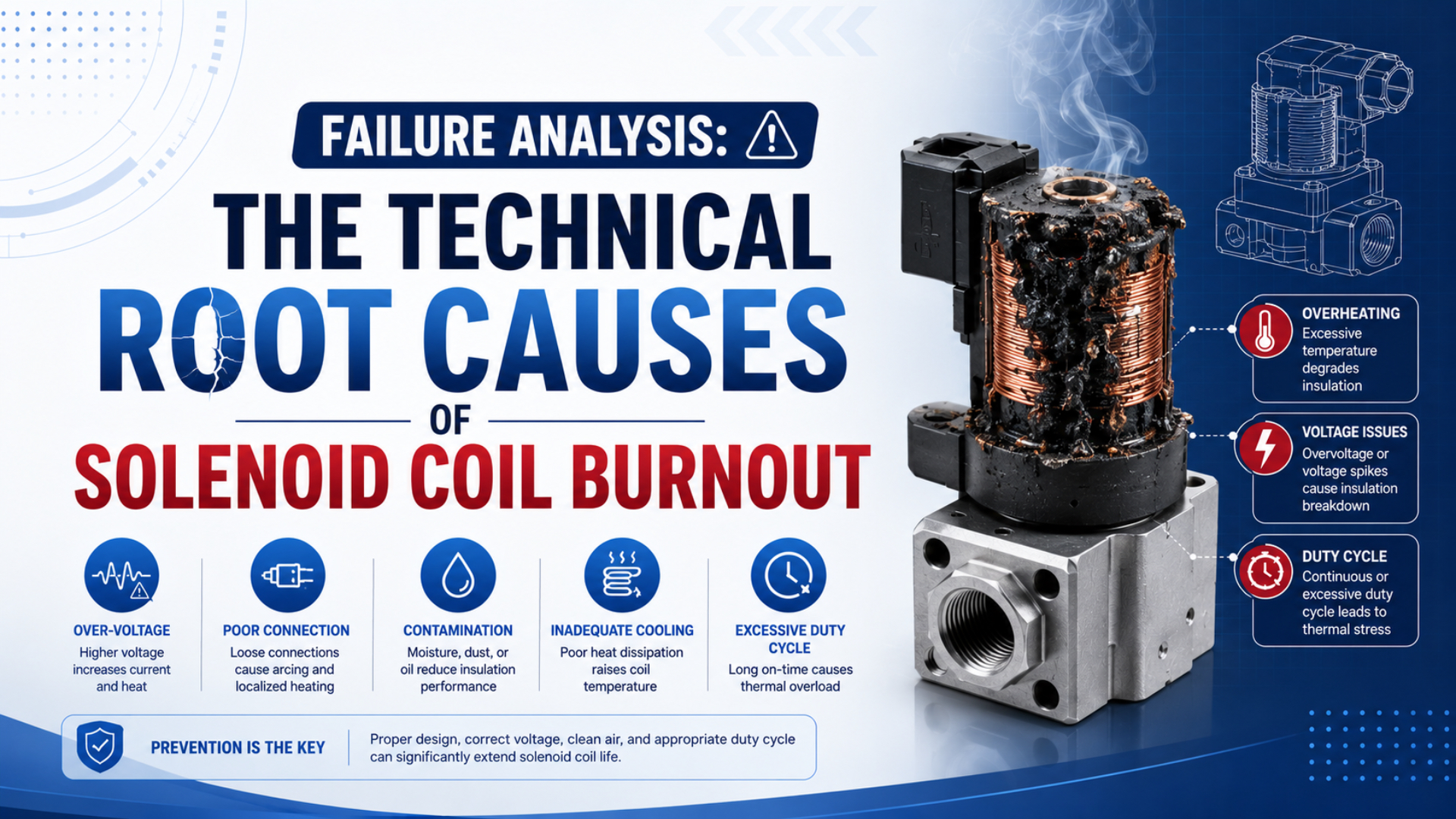
Solenoid coil burnout is the loss of electrical function after winding insulation, a connection, an embedded rectifier, or another coil component fails thermally or electrically. A blackened coil proves damage, but it doesn’t identify the initiating cause. Supply mismatch, sustained AC inrush, excessive duty, trapped heat, connector resistance, moisture, chemical attack, or an internal short can leave similar evidence.
Start with the complete coil and valve code. Record AC or DC supply, rated voltage and frequency, permissible tolerance, wattage or VA, duty rating, insulation class, ambient and medium temperatures, connector electronics, mounting arrangement, and whether the armature completed its stroke. Each field can change the diagnostic path.
Key Takeaways
- A Festo MS coil example is rated for 100% duty and ±10% voltage fluctuation.
- At fixed resistance, 110% DC voltage produces 110% current and 121% power.
- A jammed core can sustain high current in a true AC solenoid.
- Measure before replacing the coil.
What Does a Burned Solenoid Coil Actually Prove?
One Emerson M-Series manual checks 4 conditions after a burned solenoid is found: open circuit, nameplate supply voltage and frequency, ambient temperature, and a jammed core (Emerson M-Series Solenoid Pilot Manual, accessed 2026). Burned appearance doesn’t rank those competing causes.
A useful investigation separates the failure site from the initiating event. The winding may open because insulation failed between turns, a lead connection developed resistance, moisture created leakage, or a rectifier shorted. The initiating event could be overvoltage, a stalled AC armature, excessive enclosure temperature, an unsuitable connector, or simple age within the declared operating envelope.
Don’t start by asking, “Which replacement coil fits?” Start with three other questions:
- What electrical architecture is inside this coil or connector?
- What voltage, current, temperature, and movement occurred during the failed command?
- What changed before the first failure: supply, PLC output, suppressor, valve mechanics, cabinet loading, washdown, chemical exposure, or replacement part number?
The smell of burned insulation, a melted encapsulant, or an open continuity reading confirms that the component needs replacement. It does not prove overvoltage. A winding can also fail from sustained AC pickup current, repeated thermal cycling, a hot terminal, water ingress, chemical incompatibility, or an internal manufacturing defect.
Use the related solenoid-valve troubleshooting guide when the valve does not operate but the coil has not yet been condemned. The tests should distinguish loss of electrical actuation from low pilot pressure, blocked exhaust, contamination, and downstream actuator resistance.
Burned-coil evidence is the last link in the chain. Root-cause analysis works backward from the winding and connector to the current waveform, magnetic movement, supply, environment, and control sequence.
Identify the Coil Architecture Before Diagnosing Failure
Festo lists true AC and DC variants in one MS coil family, while Parker documents another family whose AC versions are DC coils with built-in full-wave rectifiers and no traditional AC inrush (Festo MS Coil Data; Parker Coil Technical Tips, accessed 2026). An “AC” label is not a complete circuit description.
Four architectures cover most industrial troubleshooting cases:
| Coil architecture | Current behavior | Failure question to ask first |
|---|---|---|
| Plain DC winding | current is primarily set by applied voltage and hot winding resistance | Is the measured voltage and energized duration inside the exact coil rating? |
| True AC winding | current falls after the armature closes the magnetic air gap | Did the core seat, or did pickup current continue? |
| Rectified AC coil | an internal rectifier feeds a DC-style winding | Is the rectifier, supply frequency range, transient rating, or winding damaged? |
| DC coil with current reduction | electronics apply pickup current, then reduce holding current | Did the driver complete the transition, and is the correct connector or sub-base installed? |
One current-reduction example comes from Festo. A VACS coil draws a nominal 138 mA for up to 70 ms, then reduces to 50 mA (Festo VACS-C-R8-1RAL Technical Data, accessed 2026). If a technician measures only the holding phase, the pickup event disappears. If the wrong connector bypasses or disrupts current reduction, a normal-looking 24 VDC supply can still accompany excess heat.
The AC-versus-DC coil guide compares response behavior. The coil-inductance guide explains why current rise and magnetic movement cannot be inferred from resistance alone.
How Do Voltage and Resistance Set DC Coil Heating?
Festo specifies ±10% permissible voltage fluctuation and 100% duty for its MS coil family; one 24 VDC version is listed at 11.5 W (Festo MS Coil Data, accessed 2026). These are model-specific limits, but they show which nameplate fields a DC investigation must preserve.
For a plain DC winding at one temperature, current follows Ohm’s law:
Here, is current in amperes, is voltage across the coil in volts, and is winding resistance in ohms at the measured temperature. Copper resistance rises as the winding heats, so a cold resistance reading and a hot energized current are not interchangeable.
The electrical input converted mainly to heat in a steady DC winding is:
Here, is input power in watts. If resistance were temporarily fixed and voltage rose to 110% of rated value, current would become 110% and power would become 121%. That is a 10% current increase and 21% power increase, not an exponential current increase. Real hot-coil values also reflect rising resistance and heat transfer.
Measure voltage at the connector while the coil is energized. A power-supply setting doesn’t include cable drop, output-module drop, relay contact resistance, shared return voltage, or connector faults. Then record current from pickup through the holding interval. Compare both traces with the exact coil, connector, and driver data.
What if the measured DC current is low rather than high? Check whether the winding is already hot, the supply collapses under load, a connection has high resistance, or electronics are reducing current as designed. A low current can explain failed pickup, but it doesn’t automatically explain a burned winding. The damage may have occurred earlier.
Resistance is most useful as a controlled comparison. Isolate the circuit according to the approved procedure, disconnect electronics that would distort the reading, record coil temperature, and compare with manufacturer data or an unused coil of the same complete code at a similar temperature. An open circuit confirms failure. A plausible resistance does not prove healthy turn-to-turn insulation.
Voltage identifies electrical stress only when paired with winding temperature and architecture. A correct 24 V reading can coexist with excess heat from failed current reduction, a hot cabinet, or a true AC mechanism hidden behind a rectifier or connector assembly.
Why Can a Jammed Armature Burn Out a True AC Coil?
Bürkert states that true AC coil current is higher with the core dropped out because the magnetic air gap lowers inductive reactance; operating without the core can overheat and burn the coil within minutes (Bürkert AC Solenoid Coils, accessed 2026). This mechanism should not be copied to every DC or rectified-AC design.
For an idealized AC winding, current depends on impedance rather than resistance alone:
Here, is impedance in ohms, is winding resistance, is inductive reactance, is RMS voltage, and is RMS current. The core position changes the magnetic circuit and therefore the effective inductance. This compact equation is a screening relationship, not a complete nonlinear solenoid model.
Festo lists 30 VA pickup and 22 VA holding for several 50 Hz MS AC coils (Festo MS Coil Data, accessed 2026). Those two ratings make the mechanical check inseparable from the electrical check. If contamination, incorrect assembly, side loading, a damaged shading ring, insufficient force margin, or foreign material prevents the core from seating, current may remain near the higher pickup condition.
Bürkert’s Type 0287 instructions state the boundary directly: a seized core can overheat an AC coil and cause functional failure (Bürkert Type 0287 Instructions, accessed 2026). Diagnose the core and guide tube under the exact valve maintenance procedure. Don’t energize a loose AC coil without its armature assembly.
An audible click is supporting evidence, not a complete test. It may come from a pilot element while the main stage remains stuck, or it may occur without full seating. Combine the sound with current waveform, work-port pressure, and the valve’s approved movement check. The valve shift-time analysis shows how to separate command, coil, valve, pressure, and machine endpoints.
What Does a 100% Duty-Cycle Rating Really Permit?
Festo marks the MS family as 100% duty, while SMC warns that continuous energization of 3 or more neighboring stations can produce a large temperature increase in one V100 installation (Festo MS Coil Data; SMC V100 Instructions, accessed 2026). Duty rating does not cancel the product’s ambient, mounting, or grouping conditions.
A 100% duty rating means the declared product can remain energized under its specified operating conditions. It does not mean any voltage, ambient temperature, connector, enclosure, manifold grouping, or medium temperature is acceptable. A coil mounted alone in free air and the same coil inside a crowded sealed panel can reach different equilibrium temperatures.
For an intermittent coil, duty cycle is:
Here, is duty cycle as a fraction, is energized time, and is de-energized time within the declared cycle. The formula doesn’t select an allowable duty. That limit must come from the exact coil data and may depend on maximum on-time, cycle duration, ambient temperature, and mounting.
Current-reduction electronics add another boundary. SMC reports that one V100 power-saving circuit reduces holding power to approximately one third after an effective energizing time above 67 ms (SMC V100 Instructions, accessed 2026). Confirm that the correct low-power option, connector polarity, and control pulse are present before treating continuous energization as the sole fault.
Thermal class is not a field temperature limit by itself. IEC 60085 establishes how electrical insulating materials and insulation systems receive thermal classifications when thermal ageing dominates (IEC 60085:2007, 2007). The complete coil still has declared ambient and medium ranges, temperature rise, enclosure, approvals, and installation restrictions.
For system-level power choices, see the low-power solenoid valve guide. Low holding power can reduce heat, but it does not excuse a jammed armature, incorrect voltage, water ingress, or an unsuitable driver.
Voltage, Frequency, Residual Voltage, and Suppression Need Separate Evidence
One Emerson manual requires at least 85% of rated voltage for its M-Series pilot, while Festo’s MS coil data declares ±10% permissible fluctuation for that different family (Emerson M-Series Manual; Festo MS Coil Data, accessed 2026). A universal voltage threshold would conflict with those product-specific limits.
Overvoltage raises power in a plain DC winding and may stress embedded electronics. Confirm RMS or DC voltage at the coil during the actual energized interval, including regulator tolerance and abnormal operating states.
Undervoltage can prevent pickup. In a true AC solenoid, incomplete seating may sustain higher current and create more heat even though the supply is low. In a plain DC coil, lower voltage usually reduces steady electrical power, but a control sequence may keep the coil energized far longer while waiting for a missing position signal.
Frequency mismatch changes true AC reactance and magnetic performance. Some coils are explicitly rated 50/60 Hz; others list separate voltage and frequency combinations. Match the complete nameplate. Don’t assume that every 50 Hz coil fails on 60 Hz or that every dual-frequency label permits any AC voltage.
Residual voltage can keep a low-power coil partially energized after the PLC output turns off. Indicator lamps, triac outputs, snubbers, leakage current, or long cables can contribute. Measure at the coil in the off state and compare with the valve manual’s residual-voltage limit.
Inductive suppression protects switching devices and changes release behavior. A diode, TVS, Zener, MOV, RC network, or integrated suppressor must match the coil and output hardware. The voltage spike created when a coil is switched off is not automatically proof that another coil on the circuit burned the winding. Capture the waveform at the failed branch and trace the shared topology.
For timing consequences, the solenoid response-time measurement guide explains why the suppressor, driver, voltage, current, and port-pressure traces need synchronized endpoints.
Environmental and Installation Evidence
Festo’s MS data lists IP65 only with the specified plug socket and gives an ambient range of -5 to 50°C for the cited family (Festo MS Coil Data, accessed 2026). The rating belongs to the assembled configuration, not to a loose coil with a missing gasket or poorly tightened connector.
Inspect the installation before cleaning or replacing anything:
| Inspection area | Evidence to record | Failure path it tests |
|---|---|---|
| Coil and connector | orientation, cable entry, seal, gasket, retaining nut, discoloration | water entry, loose retention, local connection heat |
| Thermal environment | nearby air, medium temperature, energized neighbors, cabinet ventilation, duty history | inadequate heat rejection or excessive grouping |
| Washdown | spray direction, standing water, damaged plug, assembly ingress rating | leakage through the cable entry, gasket, or housing |
| Chemicals | exposed fluid, concentration, cleaning method, contact duration | attack on housing, cable, seal, potting, or wire insulation |
| Vibration | unsupported cable mass, loose fasteners, movement marks, mounting distortion | lead fatigue, fretting, or intermittent contact |
| Manifold context | failed station, adjacent stations, shared connector or output group | local component fault versus common electrical or thermal cause |
What should a thermal image prove? It can document surface-temperature differences under controlled load, but surface temperature is not winding temperature and emissivity affects the reading. Compare identical coils under the same state, distance, settings, ambient, manifold position, and stabilization time. Use the exact product limit for acceptance.
The media-temperature guide covers heat entering through the valve body. The valve-manifold IP guide explains the complete assembly, including sealing and connector installation details.
How Should You Test a Suspected Coil Without Destroying the Evidence?
OSHA 29 CFR 1910.147 requires stored or residual energy to be relieved, disconnected, restrained, or otherwise rendered safe during covered servicing work (OSHA 1910.147, accessed 2026). Coil diagnosis can involve electricity and trapped air. Hot surfaces and springs add other hazards. So do suspended loads and commanded machine movement.
Follow the machine’s energy-control and authorized diagnostic procedures. Voltage and current measurements may require controlled energization. The same applies to waveform and temperature capture. Use properly rated instruments with guarded access. Establish the required exclusion zone and PPE, and assign personnel qualified for the circuit. Don’t remove a connector, coil, or valve operator while it is energized or pressurized.
Use this evidence sequence:
| Step | Measurement or observation | Decision it supports |
|---|---|---|
| 1 | full valve, coil, connector, and driver codes | identifies architecture and declared limits |
| 2 | symptom direction, command duration, duty history, and recent changes | defines the failed event and likely exposure |
| 3 | voltage and current waveform at the branch | separates supply, driver, winding, pickup, and holding behavior |
| 4 | manual override and approved armature or valve movement check | separates operator, pilot, main stage, and downstream load |
| 5 | ambient, medium, connector, manifold, and surface-temperature comparison | tests heat-rejection and installation hypotheses |
| 6 | isolated cold resistance and approved insulation checks | identifies open, shorted, grounded, or moisture-affected circuits |
| 7 | teardown evidence from an authorized serviceable assembly | locates winding, lead, rectifier, connector, seal, or mechanical damage |
| 8 | repeat test after correction | proves that the initiating condition was removed |
Do not apply a megohmmeter or other high test voltage through a connector containing LEDs, suppressors, rectifiers, PWM circuits, fieldbus electronics, or a PLC output unless the manufacturer explicitly permits the method and connections. Disconnecting the wrong component can also erase evidence or introduce another failure.
For example, a 24 VDC reading and an open coil prove only that rated voltage was present at the moment of measurement and the winding is now open. They don’t reveal the earlier current, cabinet temperature, water path, duty history, or whether the replacement connector contains the correct current-reduction circuit.
The highest-value trace begins before the coil fails. A synchronized record of command, voltage, current, port pressure, and temperature can show whether the electrical event preceded failed movement or followed it.
When Should You Replace the Coil, Operator, or Entire Valve?
Festo states that one MSF coil family can be replaced without interrupting the pneumatic circuit, showing that coil-only replacement is possible for some designs (Festo MSF Coil Data, accessed 2026). Other valves use integrated operators or sealed electronics, so the service boundary comes from the exact product documentation.
Replace only the coil or connector when the manufacturer permits it, the armature and guide tube move correctly, seals and valve body remain suitable, and the replacement matches voltage, current type, frequency, power, connector, suppression, duty, temperature, ingress, and approval requirements.
Replace the operator assembly when the core, guide tube, shading ring, spring, pole face, or operator seal is damaged and the approved spare includes those components. A new coil fitted over a jammed AC armature may fail again.
Replace the complete valve or manifold station when the product is not serviceable, the main stage is contaminated or damaged, the sub-base electronics have failed, an incompatible fluid or chemical has attacked multiple materials, or the manufacturer does not provide an approved repair path.
Whatever is replaced, correct the initiating condition first. Confirm supply tolerance, driver and suppressor, armature travel, pilot path, current reduction, ambient and medium temperature, enclosure heat, adjacent-coil loading, water entry, chemical compatibility, and control sequence. Then repeat the original trace in both energizing and de-energizing directions.
A replacement RFQ should include six evidence groups:
| RFQ group | Required information |
|---|---|
| Product identity | complete valve, operator, coil, connector, and manifold codes |
| Coil rating | AC/DC type, voltage, frequency, power, tolerance, duty, and suppression |
| Control circuit | PLC output or driver, residual voltage, cable length, polarity, connector electronics |
| Environment | ambient and medium ranges, washdown, chemical exposure, ingress requirement, approvals |
| Pneumatic duty | supply and pilot pressure, valve function, normal state, switching rate, energization duration |
| Failure evidence | photographs, resistance result, current trace, thermal comparison, armature condition |
This package lets the supplier confirm the whole electrical and mechanical interface. A coil that fits the tube physically may still be wrong electrically. For broader replacement logic, connect the evidence with the spool-stiction failure analysis, especially when the coil remains energized because the valve never reaches the expected state.
Solenoid Coil Burnout FAQs: What Should Maintenance Teams Verify?
The investigation must distinguish at least 4 coil architectures: plain DC, true AC, rectified AC, and current-reduced DC. Each can produce a burned or open coil, but the decisive evidence differs. Use the complete part code, measured waveform, movement result, thermal environment, and manufacturer service boundary before ordering a replacement.
Does a Jammed Valve Always Increase Solenoid Coil Current?
No. A jammed core can sustain high pickup current in a true AC solenoid because the open magnetic gap reduces inductive reactance. A plain fixed-voltage DC winding does not automatically draw more current when the valve sticks; its current mainly follows applied voltage and hot resistance. Driver and rectifier designs add other behaviors.
Is a Solenoid Coil with a 100% Duty Rating Safe at Any Temperature?
No. A 100% duty rating applies only within the product’s declared voltage, ambient, medium, mounting, grouping, connector, and heat-rejection conditions. Nearby energized coils or a sealed cabinet can raise temperature. Confirm the complete data sheet and installation restrictions instead of treating the duty percentage as an independent thermal guarantee.
Can Correct Voltage Prove That Overvoltage Did Not Cause the Failure?
No. One normal reading describes only that measurement interval. The earlier circuit may have experienced a wrong supply setting, intermittent connection, failed regulator, transient, incorrect driver, or wiring change. Capture voltage and current over the complete command and inspect event history, connector electronics, and the failed component before excluding electrical stress.
Should Coil Resistance Be Compared While the Coil Is Hot?
Only against a value corrected or specified for a comparable temperature. Copper winding resistance rises with heat, so a hot coil normally reads higher than the same coil when cold. Record temperature, isolate embedded electronics, and compare with manufacturer data or an identical known-good coil under similar conditions. Resistance alone cannot prove insulation health.
Can a Burned Coil Be Replaced Without Replacing the Valve?
Sometimes. Several valve families use replaceable coils, while others integrate the operator, electronics, or sealing interface. Coil-only replacement is appropriate only when the manufacturer permits it and the armature, guide tube, valve stage, connector, and environment pass inspection. Otherwise replace the approved operator assembly or complete valve and correct the root cause.
Sources and Technical References
This analysis uses 10 primary manufacturer, standards, and regulatory sources covering DC power, true AC inrush, rectified coils, current reduction, duty rating, insulation classes, safe servicing, and replacement boundaries. Every numeric example belongs to the cited product or stated fixed-resistance assumption; none is a universal coil-life prediction.
Publisher and author information is available on About Us. Submit technical corrections or application evidence through the contact page with the complete coil code, connector, supply, waveform, valve state, temperature, duty history, and failure photographs.
- Festo, Solenoid Coils MSFG and MSFW. Retrieved 2026-07-22.
- Festo, Solenoid Coils MSF. Retrieved 2026-07-22.
- Festo, VACS-C-R8-1RAL Solenoid Coil Technical Data. Retrieved 2026-07-22.
- SMC, V100 Series Installation and Maintenance Instructions. Retrieved 2026-07-22.
- Parker, Coils and Electronics Technical Tips. Retrieved 2026-07-22.
- Bürkert, Solenoid Coils for Alternating Current. Retrieved 2026-07-22.
- Bürkert, Type 0287 Solenoid Valve Operating Instructions. Retrieved 2026-07-22.
- Emerson, M-Series Solenoid Pilot Instruction Manual. Retrieved 2026-07-22.
- IEC 60085:2007, Electrical Insulation, Thermal Evaluation and Designation. Retrieved 2026-07-22.
- OSHA 29 CFR 1910.147, Control of Hazardous Energy. Retrieved 2026-07-22.