

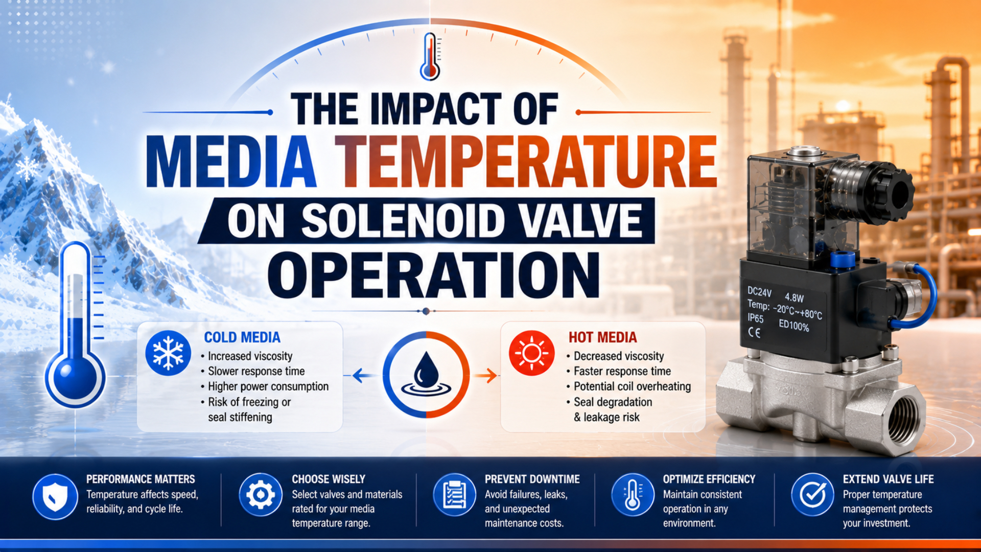
Media temperature affects a solenoid valve through heat transfer, seal behavior, fluid viscosity, pressure capability, and the temperature reached by the operator assembly. A reliable selection therefore needs four separate limits: media, ambient, coil winding, and complete-valve temperature. The lowest applicable limit, under the actual pressure and duty cycle, controls the installation.
This is why a generic statement such as “PTFE is suitable for high temperature” can’t qualify a valve. The selected part number, coil, seal set, media, pressure differential, connector, approvals, mounting, and exposure time must all remain inside their documented limits.
Key Takeaways
- Treat media, ambient, winding, and body temperature as 4 different inputs.
- Model-specific limits override generic seal-material temperature tables.
- Copper resistance rises about 0.393% per °C near 20°C, but resistance is a diagnostic, not a valve rating.
- Validate hot soak, cold soak, pressure, voltage, leakage, and shifting together.
Four Temperatures Define Solenoid Valve Operation
Bürkert lists Type 6027 medium limits from -10°C to +80°C with NBR and up to -40°C to +180°C for one PTFE-plus-PEEK configuration (Bürkert Type 6027 operating instructions, retrieved 2026). That spread shows why media temperature acts through the complete construction, not the body metal alone.
The medium first contacts the wetted path: the inlet, seat, diaphragm or plunger seal, internal guides, outlet, and sometimes a pilot passage. Heat then conducts into the valve body and operator. How far it travels depends on flow rate, dwell time, valve position, body mass, mounting, insulation on adjacent piping, and the surrounding air.
Keep these four temperatures separate:
| Temperature | What it describes | Primary decisions it affects |
|---|---|---|
| Media temperature | Fluid entering and passing through the valve | Seals, seat, viscosity, corrosion, pressure rating, pilot behavior |
| Ambient temperature | Air surrounding the installed valve and coil | Coil heat rejection, connector, electronics, enclosure and approvals |
| Winding temperature | Internal copper temperature after electrical and environmental heating | Resistance, insulation aging and available electromagnetic force |
| Body or surface temperature | Measured temperature at a defined external point | Heat-transfer trend and burn/contact protection, but not direct proof of winding temperature |
The temperatures can differ sharply. A steam valve may carry hot media while its coil sits in cooler air. A valve in a heated enclosure may have moderate air passing through it but a hot operator. A cold-room valve may see dry compressed air above the room temperature during production, then cold-soak to the room temperature during a long shutdown.
The useful engineering question isn’t “What temperature can this material survive?” It is “Which documented component limit will be reached first in this exact installed state?” That change in wording prevents a material property from being mistaken for an assembly rating.
For a general explanation of the electrical-to-pneumatic sequence, see how pneumatic solenoid valves control compressed-air flow.
How Should You Build the Operating Temperature Envelope?
Emerson lists one ASCO V365 valve at -10°C to +60°C ambient and -10°C to +90°C fluid, while its NBR construction and electrical data remain part-number specific (Emerson ASCO V365B01C-ZE30A, retrieved 2026). A valid temperature envelope must therefore preserve the exact catalog configuration and every stated condition.
Start with the ordered model code and current manufacturer documentation. Record the maximum and minimum for media and ambient separately, then add pressure differential, duty cycle, voltage tolerance, media compatibility, mounting orientation, ingress protection, hazardous-area approval, and any derating note. Don’t combine limits from different variants.
The following examples illustrate the method. They are not interchangeable recommendations.
| Documented example | Ambient range | Fluid or medium range | What the example proves |
|---|---|---|---|
| ASCO V365B01C-ZE30A, NBR | -10°C to +60°C | -10°C to +90°C | Ambient and fluid limits can differ on the same SKU |
| ASCO L145R2-Z614A, PTFE | -10°C to +80°C | +60°C to +170°C | A hot-fluid valve can still have a much lower ambient ceiling |
| Bürkert Type 6027, selected NBR configuration | Check exact variant | -10°C to +80°C | Seal and operator combination sets the published limit |
| Bürkert Type 6027, selected PTFE-plus-PEEK configuration | Check exact variant | -40°C to +180°C | A different internal construction changes the envelope |
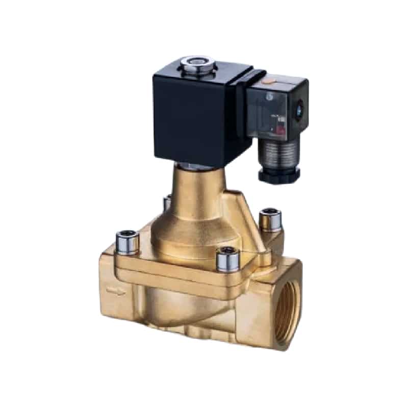
A high-temperature valve is a documented assembly. PTFE in the product name does not, by itself, establish the allowable media temperature, ambient temperature, pressure, coil duty, or steam compatibility.
Use this sequence when reviewing a candidate:
- Define the lowest and highest steady media temperatures at the valve inlet.
- Add credible startup, cleaning, shutdown, and upset transients with duration.
- Measure the local ambient near the coil, not at a distant room thermostat.
- Match the exact media, concentration, moisture content, and contamination.
- Confirm operating and differential pressure across the entire temperature range.
- Check the coil voltage, AC or DC supply, duty rating, connector, suppression, and approvals.
- Compare the project limits with the manufacturer’s combined-temperature notes.
How much margin is enough? Use an absolute temperature allowance based on sensor accuracy, process variability, local hot or cold spots, and the consequence of failure. A percentage margin on Celsius temperature is not physically meaningful because the Celsius zero is arbitrary.
This same discipline applies when approving a solenoid valve as an OEM replacement. Temperature is one compatibility gate, not a substitute for function, flow, pressure, interface, and fault-state checks.
Coil Resistance as a Thermal Diagnostic
NIST gives 0.00393 per °C as the temperature coefficient of resistance for standard annealed copper at 20°C (NIST Circular 31, retrieved 2026). That value supports a useful DC-coil temperature estimate when the winding material and cold resistance are known, but it does not replace the valve manufacturer’s thermal rating.
For a first-order estimate near the reference temperature:
Here, is winding resistance at estimated temperature , is the measured or specified resistance at 20°C, and is the copper coefficient, approximately . Use the same meter, lead compensation, and stable de-energized measurement method for comparisons.
If a DC coil measures , the estimated resistance at 80°C is:
That is about a 23.6% increase, not 40%, because the winding rose 60°C above the 20°C reference. For an ideal constant-voltage DC coil, current follows and electrical input follows . Higher resistance therefore reduces current and input power. Magnetic force and shifting margin still depend on the magnetic circuit, air gap, spring, friction, supply voltage, and valve construction.
What about AC coils? A resistance reading can reveal an open or grossly abnormal winding, but it doesn’t describe AC inrush, holding current, inductive impedance, shading-ring condition, or armature seating. Compare AC measurements only with the exact manufacturer’s procedure and known-good part.
Resistance is most valuable as a trend taken under repeatable conditions. One hot reading without a cold baseline can’t separate normal copper behavior from an incorrect coil, shorted turns, poor connector contact, low supply voltage, or excess mechanical load on the armature.
Why Do Hot and Cold Valves Miss a Shift?
SMC states that SYJ3000 response data are measured at 0.5 MPa, rated voltage, and 20°C coil temperature without a surge suppressor (SMC SYJ3000 catalog, retrieved 2026). Those controlled conditions explain why a catalog response number should not be treated as a guaranteed hot-soak or cold-start result.
At elevated temperature, a valve can lose margin through several paths:
- the winding resistance rises and a DC coil draws less current at the same voltage;
- the body transfers media heat toward the operator while the energized coil adds its own heat;
- a seal may soften, swell, harden, extrude, or lose compression depending on its compound and media;
- viscosity can fall, changing leakage, damping, and pilot behavior;
- pressure capability or hazardous-area temperature classification may impose a lower limit than the seal material.
Cold operation has a different fault pattern. Fluid viscosity may rise. Elastomers and lubricants may stiffen. Moisture can condense or freeze in pilot passages, exhausts, silencers, or connectors. Supply pressure can also fall during peak demand, leaving a pilot-operated valve below its minimum differential pressure.
This is why “hot valves switch faster” and “cold valves switch slower” are weak rules. The direction and size of the change depend on the medium, actuation principle, pressure differential, orifice, spring, seal system, lubricant, voltage, and measured location. Review direct-acting and pilot-operated solenoid valves before assigning a temperature symptom to the coil alone.
For cold pneumatic assemblies, moisture control and cold-soak starting deserve their own acceptance criteria. The sub-zero pneumatic cylinder guide covers those system-level checks. Hot actuator installations likewise need the full-component review described in the high-temperature pneumatic cylinder guide.
Which Protection Methods Actually Reduce Thermal Risk?
The ASCO L145R2-Z614A example permits fluid up to +170°C but lists a maximum ambient of +80°C for the cited configuration (Emerson ASCO L145R2-Z614A, retrieved 2026). The 90°C difference demonstrates the design goal: limit heat reaching the operator and preserve its ambient conditions without hiding the coil inside an unapproved insulating layer.
Choose controls in this order:
- Select a documented valve configuration. Match the media, temperature, pressure, seal system, coil, connector, duty, and approvals first.
- Move the operator or pilot when permitted. A manufacturer-approved remote pilot or separated actuator can keep electrical parts away from the heat source.
- Reduce radiant exposure. Use a heat shield with an air gap, while keeping required access, ventilation, and clearances.
- Limit conductive heat transfer. Review pipe length, thermal breaks, bracket design, and upstream insulation with the valve manufacturer and process engineer.
- Control the local ambient. Ventilate or condition the enclosure when the selected electrical equipment permits it.
- Instrument the installation. Log media inlet, body, coil-surface, and local ambient temperature during the worst duty cycle.
Don’t wrap the coil to “protect” it from heat. An insulating cover can trap its internally generated heat and raise winding temperature. Insulating hot piping may help people and process efficiency, but stopping insulation at the valve or adding a removable, engineered cover is often necessary for cooling, access, inspection, and maintenance.
Compressed-air spot cooling, water jackets, Peltier modules, and improvised refrigeration aren’t universal fixes. They add energy use, contamination paths, condensation risk, and new failure modes. Use them only as part of an engineered and manufacturer-approved thermal design.
A Temperature-Validation Test Matrix
OSHA 29 CFR 1910.147 covers unexpected release of pneumatic, electrical, thermal, and other hazardous energy during servicing (OSHA, Control of Hazardous Energy, accessed 2026). Temperature validation must therefore separate safe de-energized inspection from controlled live testing performed by qualified personnel under the site’s approved procedure.
Build a test matrix around actual boundary conditions, not a single room-temperature cycle.
| Test stage | Conditions to stabilize | Measurements | Acceptance evidence |
|---|---|---|---|
| Baseline | Nominal media, ambient, pressure and voltage | leakage, current, resistance, shift time, outlet pressure | Reference trace and part identity |
| Cold soak | Minimum specified ambient and media after longest shutdown | first-command voltage, pressure, response, leakage, repeat strokes | Starts and shifts without sticking or ice-related restriction |
| Hot steady state | Maximum continuous media, ambient and duty | coil surface, body, inlet/outlet media, voltage, current, leakage | All documented limits and machine criteria pass |
| Hot restart | Worst shutdown followed by restart | pull-in, pressure differential, response and fault indication | Valve reaches commanded state reliably |
| Temperature cycling | Defined low/high transitions and dwell times | leakage trend, connector condition, resistance baseline | No progressive drift or damage |
| Fault injection | Approved low voltage, low pilot pressure, blocked-flow simulation or sensor fault | safe response, alarm, recovery and record | Failure is detected and machine state remains acceptable |
Before opening a connector or pneumatic line, isolate electrical and pneumatic energy, relieve stored pressure, control gravity or spring motion, and verify the safe state. Live voltage, current, response-time, and temperature measurements require a separate energized-test plan with defined boundaries and competent personnel.
Run one-factor fault injections before combining them. Low voltage plus hot soak plus marginal pilot pressure may reproduce the field failure, but it won’t identify which boundary is weak. Establish each threshold separately, then test the credible combined worst case.
Record the exact part code, coil code, seal code, firmware or PLC revision when relevant, instruments, sensor locations, calibration status, stabilization time, media, pressure, voltage, and pass/fail limits. Without that context, a temperature log is difficult to reproduce.
What Should You Measure When a Valve Becomes Unreliable?
Bürkert’s Type 6027 instructions pair medium limits with seal and solenoid variants, while NIST quantifies copper resistance change at 0.00393 per °C near 20°C (Bürkert; NIST, retrieved 2026). Together, those facts support a two-track diagnosis: verify the selected assembly and measure the electrical and thermal state.
| Symptom | Measure first | Likely branches to separate |
|---|---|---|
| Works cold, fails after warm-up | loaded coil voltage, current, body and local ambient temperature | voltage drop, normal resistance rise, winding damage, heat soak, tight armature, low pilot margin |
| Fails on first cold start | media and body temperature, point-of-use pressure, moisture/dew-point records | stiff seal or lubricant, ice, blocked exhaust, low pilot differential, connector condensation |
| Coil is hot but valve shifts | exact coil code, voltage, duty rating, ambient, stable current | normal continuous-duty heat, overvoltage, wrong frequency, poor heat rejection |
| Clicks but no downstream pressure | inlet and outlet pressure, manual override result, exhaust restriction | blocked port, insufficient differential, stuck main stage, incorrect function, closed isolation valve |
| Leakage rises with temperature | leakage path, media identity, pressure and seal code | incompatible or damaged seal, thermal expansion, seat contamination, pressure derating |
| Intermittent after washdown | connector ingress, insulation resistance under approved procedure, corrosion | water entry, thermal shock, damaged cable gland, unsuitable enclosure |
A click isn’t proof of a complete shift. An indicator LED proves only that voltage reached part of the connector circuit. Follow the diagnostic sequence in how to troubleshoot a failing pneumatic solenoid valve, then add temperature and heat-soak measurements at defined locations.
Stop testing if the coil shows discoloration, cracked encapsulation, odor, melted insulation, unexpected smoke, visible arcing, severe leakage, or a temperature above the documented limit. Replace the damaged component only after the root cause and installed conditions have been identified.
What Belongs in a Temperature-Critical Solenoid Valve RFQ?
Bürkert’s Type 6027 documentation contains medium ranges spanning at least 220°C from the cited -40°C lower limit to +180°C upper limit across different constructions (Bürkert Type 6027, retrieved 2026). An RFQ that says only “high-temperature valve” cannot identify which construction, pressure condition, or operator is required.
Send the supplier a reproducible operating envelope:
- exact media name, concentration, contamination and phase;
- continuous, startup, cleaning and upset media temperatures with dwell times;
- minimum and maximum local ambient at the coil;
- minimum, normal and maximum inlet and outlet pressure;
- required differential pressure at actuation;
- flow, port function, normal state, orifice or Cv/Kv target;
- supply voltage, AC or DC, frequency, allowable drop, duty and switching rate;
- seal, body, connector, enclosure and hazardous-area requirements;
- mounting orientation, nearby radiant heat, insulation and enclosure details;
- leakage, response, hot-start and cold-start acceptance limits;
- photos, nameplate, circuit, dimensional drawing and failure history for a replacement.
Ask the supplier to return the complete part code and the document revision supporting every limit. If a quote lists only a seal material and a maximum temperature, it isn’t a complete technical response.
Solenoid Valve Temperature FAQs: What Should Engineers Check?
The cited ASCO L145R2-Z614A configuration separates a +170°C fluid ceiling from a +80°C ambient ceiling, a difference of 90°C (Emerson ASCO L145R2-Z614A, retrieved 2026). These questions focus on the practical distinctions that prevent a hot-fluid rating, insulation class, or material limit from being applied to the wrong part of the valve.
Is media temperature the same as solenoid coil temperature?
No. Media temperature is measured in the fluid path, while winding temperature is inside the energized coil. Heat can conduct from the medium into the operator, and the winding adds electrical heat. Measure media, local ambient, and defined surface points separately; estimate winding temperature only with an approved method and suitable baseline.
Can a Class H coil operate in 180°C ambient air?
Not automatically. Class H describes an insulation-system thermal class, not the complete valve’s ambient rating. The operator still has self-heating, and its connector, encapsulation, approvals, seals, electronics, and installation impose limits. Use the ambient range published for the exact valve-and-coil code rather than the insulation-class number alone.
Does PTFE make every solenoid valve suitable for steam?
No. PTFE may be one seat or sealing material, but steam service also depends on its grade and geometry, body and internal materials, pressure-temperature rating, operator temperature, differential pressure, cycle duty, and approvals. Select a complete steam-rated model and verify the manufacturer’s media table for the exact configuration.
How much temperature margin should a solenoid valve have?
Use an absolute margin derived from measurement uncertainty, process variation, local hot or cold spots, transient duration, and failure consequence. Don’t apply a percentage to Celsius temperature. Document both the worst credible condition and the margin, then confirm the entire ordered configuration stays within its published operating envelope.
Should a hot solenoid coil be wrapped with insulation?
Usually not unless the manufacturer explicitly approves the arrangement. A coil generates its own heat, so wrapping it can reduce heat rejection and raise winding temperature. Prefer a correctly rated operator, thermal separation, shielding with an air gap, ventilation, remote piloting, or enclosure control supported by the component documentation.
Sources and technical references
- Bürkert. Type 6027 2/2-way solenoid valve operating instructions. Medium and ambient limits by solenoid and seal construction. Retrieved 2026-07-22.
- Emerson. ASCO V365B01C-ZE30A and ASCO L145R2-Z614A. Part-specific ambient, fluid, seal and electrical data. Retrieved 2026-07-22.
- NIST. Copper Wire Tables, Circular 31. Standard annealed-copper resistance and temperature coefficient at 20°C. Retrieved 2026-07-22.
- SMC. SYJ3000 catalog. Response-time test conditions and valve specifications. Retrieved 2026-07-22.
- OSHA. 29 CFR 1910.147, Control of Hazardous Energy. Electrical, pneumatic, thermal and stored-energy controls for servicing. Accessed 2026-07-22.