

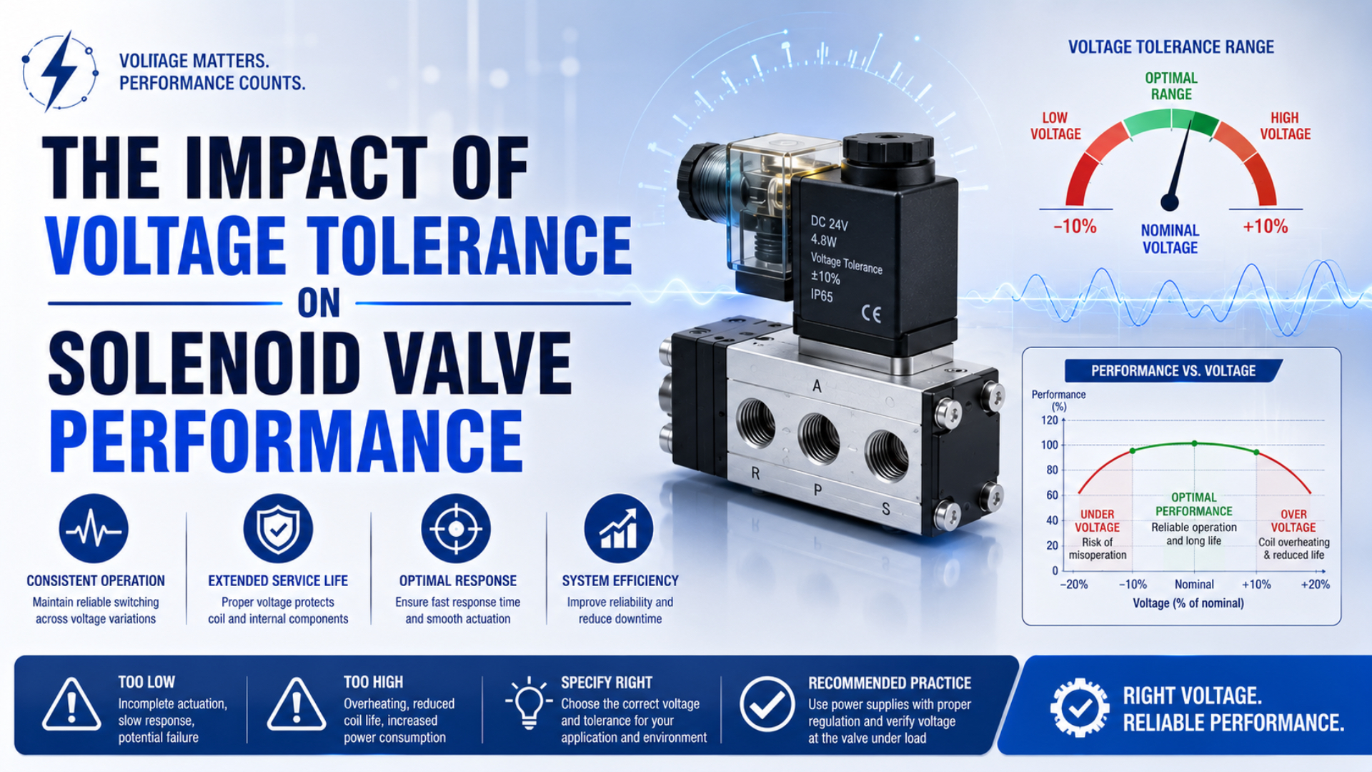
Solenoid valve voltage tolerance is the allowable voltage range for one documented coil and valve configuration, measured at the coil terminals under the stated operating conditions. It isn’t a universal ±10% rule. A 24 VDC power supply can read 24.0 V with the output off while the energized coil receives less because of an output transistor, long cable, connector resistance, shared load, or current-limiting driver. What must the installed valve prove? It must pull in, remain shifted, release, and stay within its thermal limits at both ends of its published range. Measure voltage where the coil uses it.
Key Takeaways
- One SMC series permits -15% to +10%, while other documented coils use ±10%.
- Pull-in can require more current than holding.
- Check voltage at the energized coil terminals, not only at the power supply.
- Validate hot and cold operation at the real pressure differential.
Why Is Solenoid Valve Voltage Tolerance Model-Specific?
SMC VS4 permits -15% to +10%, while Bürkert Type 5411 specifies ±10% (SMC; Bürkert, retrieved 2026). Both offer 24 VDC versions, proving nominal voltage alone cannot define the permissible window. Use exact model documentation.
At 24 VDC, the SMC window reaches 20.4 V and a ±10% Festo VUVG example reaches 21.6 V (Festo, retrieved 2026). Both stop at 26.4 V. ASCO’s Series 275/375 provides a third boundary: +10%/-5% for its listed 12 or 24 VDC versions, versus +10%/-15% for specified AC versions. Consequently, its 24 VDC example starts at 22.8 V, which is 2.4 V above the SMC lower limit (ASCO, retrieved 2026). These arithmetic translations compare documents; they do not approve another valve.
In our experience reviewing replacement RFQs, a bare “±10%” line creates more questions than it answers. The useful record binds that percentage to coil and valve codes. Electrical type, frequency, connector and suppression follow. So do duty rating, ambient range, pressure differential and pilot requirement. Record the document revision as well. Otherwise maintenance can install a physically compatible coil with another electrical window. Its release behavior or approval can differ from the part that passed the machine test, and its temperature capability can fall short of the installation.
What Does Low Voltage Change During Pull-In?
Festo separates pull-in from holding current. One 2024 datasheet specifies 138 mA nominal pick-up current for up to 70 ms, then 50 mA after reduction; low voltage matters most before the armature seats and completes that starting interval (Festo, 2024).
Pull-in is demanding. At the starting air gap, static friction and spring load resist motion; a direct element can also oppose pressure force. Pilot operation adds minimum differential pressure plus pilot flow. Once the armature seats, a smaller magnetic gap can permit lower holding current. Weak energization can buzz or chatter. Motion can be late, or an audible click can occur without the commanded pneumatic path. That sound proves an impact occurred somewhere; it cannot confirm full spool travel or pilot transfer. Outlet pressure and required flow remain unproven. Follow the solenoid troubleshooting sequence to separate those branches.
Treat the familiar current-squared magnetic relationship as a screening model. Under fixed cold resistance, 90% voltage gives 90% current; an ideal current-squared term therefore falls to 81%. Reality is messier. Working gap and steel saturation matter, while leakage flux or pole geometry can reshape the curve. Spring load, friction, pressure, temperature, and driver waveform add separate uncertainty. For the full force-stroke method, use the plunger-force guide.
Why Does Hot-Coil Voltage Margin Shrink?
NIST gives as standard annealed copper’s resistance-temperature coefficient at a 20°C reference condition (NIST, retrieved 2026). The effect is measurable. A first-order 60°C winding rise adds about 23.6% resistance, reducing DC current and pull-in margin when terminal voltage stays unchanged.
For a voltage-driven DC coil, start with the installed electrical state:
denotes current at winding temperature . The measured energized-terminal voltage is , and is hot winding resistance. This equation excludes AC inductive impedance and current-regulated PWM behavior. If resistance rises by 23.6% while terminal voltage stays fixed, the ideal ratio becomes . Do not relabel that result as a guaranteed 19.1% force loss. Armature position and magnetic-circuit geometry govern the conversion from current to force, while saturation and leakage can change it further.
Coil surface temperature isn’t winding temperature. Nor do nominal watts reveal hot pull-in current. See media temperature and solenoid operation for a repeatable resistance-based diagnostic that does not pretend to be an assembly rating.
When we review an intermittent warm failure, the cold-bench result is only a baseline. The decisive test applies the documented lower voltage after duty and ambient conditions have stabilized the coil. A unit can pass cold, warm gradually, and then lose current margin even though its source voltage never changes. Record coil-terminal voltage and current on the same time base as winding-temperature estimate, inlet pressure, outlet pressure, command signal, and confirmed valve state. That aligned trace distinguishes an electrical boundary from a pressure or mechanical problem.
Finding Voltage Loss at the Coil Terminals
SMC notes approximately 0.5 V of transistor drop in one SY-series power-saving circuit and tells users to include it in the allowable fluctuation check (SMC SY precautions, retrieved 2026). On a nominal 24 V circuit, that internal drop consumes about 2.1% before cable or connector losses are counted.
Use a loaded voltage budget:
is source voltage during the command. Those drop terms cover the PLC or driver output, both cable conductors, and contacts or connectors. Add any verified series element. A reading directly across the coil terminals captures the combined result without hiding it behind separate assumptions.
During diagnosis, capture the first command after the relevant hot or cold soak. Repeat it during cycling and when neighboring loads switch. Bandwidth matters. A slow display can average away a short pull-in dip or obscure a PWM peak. De-energized resistance or continuity testing requires isolation. Energized voltage and current measurements need qualified personnel plus the site’s electrical-safety procedure. Off-state behavior deserves its own trace because leakage can delay release or keep a low-power operator partly energized. Check that branch after command removal or when dropout is slow.
How Should AC, DC, and Current-Controlled Coils Be Treated?
Electrical architecture changes the test. ASCO lists +10%/-5% for DC and +10%/-15% for AC in one valve family. TI’s DRV110 instead applies a peak current and then a lower hold current (ASCO; Texas Instruments, retrieved 2026). These are different electrical systems, so one voltage-force rule cannot describe all three.
| Coil or driver type | What must be checked | Common wrong shortcut |
|---|---|---|
| Plain DC resistance coil | Loaded terminal voltage, hot resistance, pull-in current, steady current, duty | Applying cold nameplate watts at every temperature |
| AC coil | Voltage, frequency, inrush, holding current, armature seating, shading components | Treating it as a DC resistance load |
| Peak-and-hold driver | Minimum peak current, peak duration, hold current, PWM behavior, fault protection | Checking only average voltage with a slow meter |
| Pilot-operated valve | All electrical checks plus minimum pilot differential and exhaust condition | Calling every missed shift an electrical fault |
Suppression hardware changes the circuit too: a diode or Zener can alter release time, and varistors or electronic clamps can change controller-side voltage. Treat the valve and output-module instructions as a matched pair. AC and DC versions can share a body yet require different frequencies, connectors, suppressors, and replacement codes. When timing is part of acceptance, use the boundaries in the solenoid response-time guide. For electrical architecture, see the AC versus DC coil comparison.
A Voltage-Tolerance Commissioning Test Matrix
Bürkert lists 50 ms opening and 30 ms closing for Type 5411 at 20°C, 6 bar inlet pressure, 1 bar pressure difference, and rated voltage (Bürkert, retrieved 2026). Those conditions make its catalog timing a test reference, not a machine guarantee.
Stay inside the published limits. Never drive a component outside its rating merely to find a destructive threshold or manufacture an artificial failure.
| Test state | Electrical condition | Pneumatic and thermal condition | Acceptance evidence |
|---|---|---|---|
| Identity check | Exact coil voltage, AC/DC type, frequency, connector, driver | Exact valve code and function | Installed parts match approved documents |
| Cold start | Published lower voltage boundary | Minimum ambient, first command, worst valid pressure | Complete shift and release without chatter |
| Hot pull-in | Published lower voltage boundary at coil terminals | Stabilized duty, maximum valid ambient and pressure differential | Current and pneumatic state meet acceptance limits |
| Upper voltage | Published upper boundary | Maximum duty and ambient | No abnormal current, temperature, noise, leakage, or failed release |
| Shared-load event | Minimum observed source voltage | Other outputs and actuators operating | Terminal voltage and shift remain inside limits |
| Off-state test | Output commanded off | Worst leakage-current path and hot coil | Valve releases within the required time |
| Repetition | Boundary voltage across specified cycles | Real load, pilot pressure, exhaust and flow | No missed shifts or progressive drift |
Define two acceptance results: an electrical boundary and a pneumatic outcome. A record saying “the supply remained above 21.6 V” is incomplete when the exact valve uses another range or the coil terminals were not measured. An audible click is equally incomplete when outlet pressure never confirms the commanded path. Before opening a connector or air line, isolate hazardous electrical energy and stored pneumatic pressure under the site’s approved procedure. OSHA 29 CFR 1910.147 covers unexpected energy during servicing; qualified personnel need a separately controlled method for live diagnostics (OSHA, accessed 2026).
What Should a Voltage-Critical Solenoid Valve RFQ Include?
Across the cited 24 VDC examples, lower boundaries range from 20.4 V to 22.8 V. That 2.4 V span shows why an RFQ must identify the complete assembly and driver configuration plus the document revision supporting its allowable range, not merely request a “24 VDC solenoid valve.”
Send the supplier these conditions:
- valve function and normal state;
- complete valve, coil, and connector codes plus the required fail state;
- measured supply minimum and maximum at the machine, with AC/DC type and frequency;
- PLC or driver part number, output topology, available current, internal voltage drop, channel grouping, short-circuit behavior, protection method, PWM frequency, peak-current level, peak duration, hold-current level, and diagnostic leakage;
- conductor size and total circuit length;
- connector indicators, suppression components, contact ratings, terminal material, and expected off-state leakage;
- continuous duty, command frequency, energization time, local ambient extremes, enclosure ventilation, and neighboring heat sources;
- medium, validated pressure range, minimum pilot differential, required flow, exhaust restrictions, contamination controls, and mounting orientation;
- measurable pull-in, release, outlet-pressure, and response-time criteria;
- applicable approvals and replacement traceability.
Require the supplier to return exact ordered codes and the applicable document revision. Physical fit isn’t electrical equivalence. A substitute can alter the voltage window or current waveform. Release time may change. So can connector polarity, frequency compatibility, thermal limits, suppression behavior, and approval status. Use the OEM solenoid compatibility guide for the remaining function, pressure, flow, interface, and fault-state checks.
Solenoid Valve Voltage Tolerance FAQs
Across the four cited manufacturer examples, the nominal 24 VDC lower boundary spans 20.4 V to 22.8 V. These answers keep model limits separate from installed voltage loss and coil temperature, then connect the electrical result to pneumatic load and proof of the commanded valve state.
What voltage tolerance should I specify for a solenoid valve?
Specify the range published for the exact coil and valve code, then confirm the matching driver and connector. Keep every associated condition. Duty and ambient temperature remain part of that rating, as do pressure differential and approvals. Never substitute a generic ±10% rule. Project limits must fit inside the documented window with measurable commissioning criteria.
Where should solenoid valve voltage be measured?
Measure directly across the energized coil terminals during pull-in and steady operation. Repeat it under the worst shared load. After the relevant hot or cold soak, capture the same points again because a power-supply reading cannot reveal losses across the output transistor, both cable conductors, terminals, connector, and series protection components.
Can a 24 VDC solenoid valve operate at 20 V?
Only when the exact manufacturer documentation permits that value under the installed conditions; the cited SMC window reaches 20.4 V, whereas the ASCO DC example starts at 22.8 V. Twenty volts fails both examples. Nominal voltage or a different valve family’s limit cannot approve the installed part.
Why does a solenoid click but fail to pass air?
A click isn’t proof of flow. Check loaded coil voltage and current, then measure inlet and outlet pressure while confirming the pilot differential. Manual override behavior, spool or poppet travel, exhaust restriction, and contamination separate the remaining branches. Some failures combine electrical loss with pneumatic load and appear only during production.
Does overvoltage always burn out a solenoid coil?
Not immediately, but operation above the published upper boundary is unapproved and can raise electrical input or thermal stress depending on the coil and driver. Confirm actual terminal voltage, current, duty, ambient temperature, heat rejection, and protection behavior. Replace any damaged coil only after the cause and full installed conditions are documented.
Sources and technical references
- SMC, Series VS4 Direct Operated Solenoid Valve catalog, rated voltages and -15% to +10% allowable fluctuation. Retrieved 2026-07-22.
- SMC, Series SY Specific Product Precautions, power-saving circuit timing, transistor voltage drop, and suppression notes. Retrieved 2026-07-22.
- Festo, VACF-B-R4 Solenoid Coils datasheet, December 2024, ±10% fluctuation plus nominal pick-up and reduced holding current. Retrieved 2026-07-22.
- Festo, VUVG-LK10 solenoid valve technical data, 24 VDC coil and ±10% permissible fluctuation. Retrieved 2026-07-22.
- Bürkert, Type 5411 datasheet, voltage tolerance and stated switching-time test conditions. Retrieved 2026-07-22.
- Emerson ASCO, Series 275/375 catalog, model-family AC and DC voltage ranges. Retrieved 2026-07-22.
- Texas Instruments, DRV110. Peak-and-hold controller. Retrieved 2026-07-22.
- NIST, Copper Wire Tables, Circular 31, standard annealed-copper resistance-temperature coefficient. Retrieved 2026-07-22.
- OSHA, 29 CFR 1910.147 Control of Hazardous Energy, servicing energy-control requirements. Accessed 2026-07-22.