

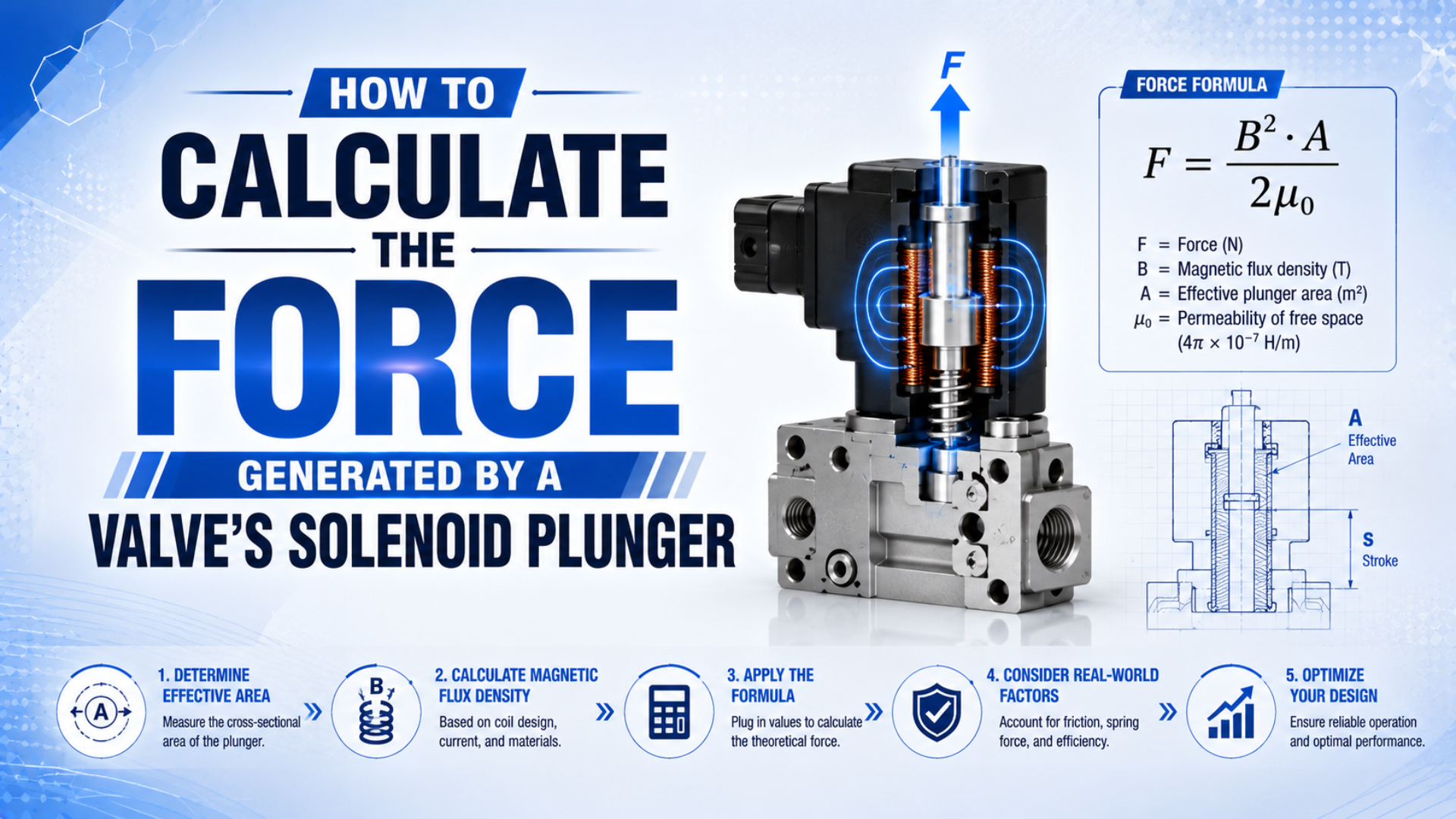
Calculate a valve solenoid’s plunger force in two stages. First, estimate magnetic attraction at each relevant air gap. Then compare the available force with the spring, pressure, friction, and dynamic loads that oppose motion. The familiar magnetic-pressure equation is useful for screening, but a real force-stroke curve usually needs measured data or a field model.
The distinction matters. A calculation can predict substantial force at the closed position yet still miss the starting force needed to open the valve. Pole geometry, magnetic saturation, leakage, coil temperature, and supply behavior all change the result.
Key Takeaways
- The ideal pole-face estimate is .
- A direct-acting valve must also overcome pressure, spring, friction, and acceleration loads.
- COMSOL documents three practical force methods: Maxwell stress, tensile force, and virtual displacement.
- Check force across the full stroke, especially at the initial air gap.
What Does Solenoid Plunger Force Actually Mean?
Bürkert describes its Type 6013 as a direct-acting plunger valve up to DN 6.0 and offers a kick-and-drop coil option (Bürkert Type 6013, retrieved 2026-07-22). Plunger force is the electromagnetic attraction available at a stated current, position, temperature, and magnetic-circuit condition, not a single permanent rating.
The force changes as the plunger moves. At the open position, the main air gap is usually largest and the magnetic circuit has its highest reluctance. Near the seat, the gap is smaller, the inductance is different, and the iron may be closer to saturation. The result is a force-stroke curve rather than one force value.
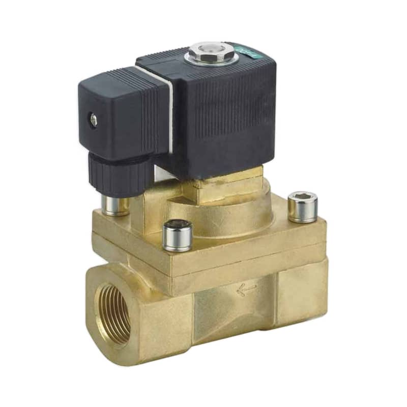
Start by defining the force location:
- Initial or pull-in position: the de-energized gap where motion must begin.
- Mid-stroke position: a point where acceleration, spring compression, or flow forces may change.
- Seated or holding position: the minimum working gap after the plunger has completed its stroke.
That definition prevents a common mistake: comparing closed-gap magnetic force with open-gap load. For more background on the mechanism, see how pneumatic solenoid valves convert an electrical command into air-flow control.
The force number that matters is the smallest positive margin along the required motion, not the largest number on the curve. If the plunger cannot start, a generous seated-force result has no practical value.
What Must the Plunger Overcome Inside a Valve?
ASCO divides a solenoid valve into 2 functional units, the electromagnet with its core and the valve body with one or more orifices (ASCO Engineering Information, retrieved 2026-07-22). A usable calculation must connect the electromagnetic force from the first unit to the mechanical and fluid loads in the second.
For a direct-acting, normally closed valve, use this static opening-force budget:
Here, is plunger position, is the worst inlet-to-outlet pressure differential, and is the effective pressure-loaded seat area. The spring, friction, and flow-force terms must use the same direction convention. If a load assists opening, give it a negative sign rather than silently discarding it.
For a dynamic check, include the moving mass and target acceleration:
The mass includes the plunger and any coupled moving parts. The damping coefficient represents velocity-dependent resistance in a simplified model. COMSOL uses the same spring-mass-damper structure when modeling a transient electromagnetic plunger (COMSOL linear plunger model, 2015).
| Load term | Minimum input needed | Frequent error |
|---|---|---|
| Pressure load | Worst differential and effective seat area | Using port thread area instead of seat area |
| Spring load | Preload and spring rate through the stroke | Checking only the free spring force |
| Friction | Seal, guide, surface, and temperature condition | Treating friction as a fixed percentage |
| Flow force | Flow direction and valve geometry | Ignoring it during high-flow switching |
| Inertia | Moving mass and required acceleration | Using a static force balance for response time |
Pressure force grows with effective area. A larger port label doesn’t establish that area, so use the seat drawing or manufacturer force data. The related guide to pressure differential and pneumatic force explains why inlet pressure alone is not enough.
When Is the Magnetic-Pressure Formula Useful?
Ansys demonstrates an axisymmetric solenoid model with 650 windings and 1 amp per winding, while explicitly assuming no iron saturation and negligible external leakage (Ansys solenoid actuator tutorial, 2025). Those assumptions show where the magnetic-pressure equation belongs: an early estimate for a simple, nearly uniform air gap.
For a field that is approximately normal to a flat pole face, the ideal attraction is:
In this equation:
- is ideal normal force in newtons.
- is flux density in the working air gap in tesla.
- is the effective pole-face area carrying that flux in square metres.
- is the vacuum magnetic permeability, approximately for engineering work.
Since the 2019 SI revision, is measured rather than defined as an exact constant. At adoption, NIST reported a relative standard uncertainty of only , far below the uncertainty in a practical valve’s geometry and flux distribution (NIST SP 330, Section 2, 2019).
What does the formula leave out? It does not calculate from coil turns and voltage. Nor does it automatically include fringing, leakage, conical pole faces, multiple gaps, residual gaps, nonlinear steel, or pressure and spring loads. Treat the answer as ideal magnetic attraction at one operating point.
Worked Example: Estimating Ideal Pole-Face Force
Using the NIST engineering value for , consider a flat circular pole with and a modeled gap flux density of (NIST SP 330, Section 2, 2019). These are illustrative inputs, not a universal valve rating, and the result is an ideal screening value.
First, convert the diameter to metres and calculate the circular area:
Then apply magnetic pressure:
That is not yet the valve’s guaranteed pull-in force. Suppose the worst-position load budget is . The ideal static margin would be:
An 8 N ideal margin may disappear after leakage, saturation, coil heating, voltage tolerance, friction spread, and manufacturing tolerances are included. Don’t convert it into a generic safety factor. Instead, calculate the minimum-current force-stroke curve for the actual geometry and verify the critical points on hardware.
A field solver isn’t required for the arithmetic above; it is required when the assumed and are no longer defensible. The real modeling question is therefore not “Can I divide by ?” but “Do I know the gap field well enough for that simplification?”
Why Does the Simple Current-and-Gap Formula Break Down?
The same Ansys example that uses 650 turns also calls its no-saturation and negligible-leakage assumptions simplifications; it calculates force by both virtual work and Maxwell stress for comparison (Ansys, 2025). A turns-current-gap equation is therefore a magnetic-circuit model, not a universal description of every valve solenoid.
For one dominant uniform air gap and linear magnetic material, a rough relationship is:
Here, is coil turns, is current, is ideal pole area, and is the dominant air gap. The equation predicts an inverse-square gap relationship and a square relationship with current. Both are conditional.
Why can the prediction fail?
- Iron saturation: increasing ampere-turns no longer produces a proportional increase in flux.
- Leakage and fringing: not all flux crosses the intended pole area, and the gap field isn’t uniform near edges.
- Multiple reluctances: guide-tube sections, residual gaps, nonmagnetic sleeves, and joints can rival the main gap.
- Geometry changes: tapered poles and side-working gaps create force components that a flat-area model misses.
- Current isn’t fixed by voltage alone: resistance rises as the winding heats, and inductance changes with plunger position.
Core permeability cannot be used as a direct force multiplier. Once the iron reluctance becomes small compared with the air-gap reluctance, raising relative permeability further may have little effect. At high flux density, saturation can dominate instead.
This is also why a fixed “fringing correction” is unsafe. Edge effects can change the effective field distribution in either a helpful or harmful way for the intended axial force, depending on pole shape and the integration surface.
Virtual Work and FEA for Real Geometry
A Heilbronn University paper documents 3 solenoid-force methods in COMSOL: Maxwell stress, Maxwell tensile force, and virtual displacement (Vogel and Ulm, 2011). These methods are appropriate when the force-stroke curve depends on tapered poles, nonlinear material data, leakage paths, or more than one significant air gap.
For a linear magnetic system driven at constant current, magnetic co-energy gives:
If inductance describes the position dependence, this becomes:
COMSOL presents the same inductance-gradient relationship for force calculated from magnetic energy (COMSOL differential inductance, 2017). It explains why a coil’s inductance-versus-position data can be more useful than its nominal wattage.
| Method | Best use | Main limitation |
|---|---|---|
| Magnetic pressure | Fast screening at one simple air gap | Requires a defensible local gap field and effective area |
| Lumped reluctance model | Early turns, gap, and geometry studies | Loses accuracy with leakage, saturation, and complex poles |
| Virtual work or co-energy | Force from energy change with position | Needs a sound field or inductance model |
| Maxwell stress integration | Detailed force on real geometry | Sensitive to mesh, material data, boundaries, and integration setup |
| Bench force-stroke test | Final validation of the built unit | Applies only to tested tolerances and conditions |
Build a position sweep from the de-energized gap to the seated residual gap. Repeat it at minimum operating current, nominal current, and any permitted short-duration peak current. For a DC voltage-driven coil, couple the electrical and thermal models so winding resistance isn’t frozen at room temperature.
Two independent force methods are more valuable than an extra decimal place. Ansys compares virtual-work and Maxwell-stress results in its solenoid example; agreement between methods is a useful model check, while disagreement points to mesh, boundary, or integration-surface problems.
How Should Pull-In and Holding Force Be Checked?
Texas Instruments’ DRV110 uses 2 commanded current levels: a fast-rising peak level for valve activation and a lower hold level to reduce power and thermal dissipation (TI DRV110, retrieved 2026-07-22). This control strategy separates pull-in current from hold current, but it does not establish a universal ratio between pull-in and holding force.
Pull-in force is the magnetic force available at the starting position and current waveform. Compare it with spring preload, pressure load, static friction, and the acceleration needed to complete the stroke before the peak-current timer expires.
Holding force is the force available after the plunger reaches its seated or commanded position. The smaller residual gap often improves magnetic attraction, so the required hold current may be lower. It still must exceed the return spring, pressure, vibration, and any force needed to keep the sealing or pilot element in position.
Could you infer both from coil watts? No. The same nominal power can correspond to different turns, wire resistance, inductance, pole geometry, stroke, materials, and thermal state. Use current, position, and force-stroke data.
For a voltage-driven DC coil, begin with:
As copper winding resistance rises with temperature, current and force margin can fall. Check the minimum allowed supply voltage at the coil terminals, including wiring and driver losses, and the maximum stabilized winding resistance. If switching time matters, the solenoid response-time measurement guide explains why current rise and mechanical travel must be measured separately.
AC coils need their manufacturer-specific current, shading-ring, frequency, inrush, and holding data. Don’t apply a blanket AC-versus-DC force percentage. The separate AC and DC solenoid coil comparison covers that electrical distinction.
A Practical Solenoid Force Calculation Workflow
The COMSOL paper’s 3 force methods and Ansys’s 2-method comparison point to a staged workflow: screen with simple equations, model the actual force-stroke curve, then validate hardware (Vogel and Ulm, 2011; Ansys, 2025). Each stage should reduce a named uncertainty rather than produce an unsupported “accuracy” percentage.
In our experience, a one-page force-stroke worksheet is more useful than a single headline force. It keeps the magnetic assumptions, valve loads, electrical limits, and test conditions visible in the same decision record.
- Define the valve state. Record direct, semi-direct, or pilot operation; normally open or closed behavior; stroke; seat diameter; and flow direction. The direct-acting versus pilot-operated valve guide helps identify which load the plunger actually moves.
- Build the opposing-force budget. Calculate pressure load from the effective seat area, add spring force through the stroke, and document friction, flow-force, inertia, and orientation assumptions.
- Establish electrical limits. Use minimum coil-terminal voltage, hot resistance, driver current limits, duty cycle, and peak-current duration. Don’t substitute nameplate power for actual current.
- Run an ideal magnetic screen. Use magnetic pressure only if gap flux density and effective area are defensible. Use the simple turns-current-gap relationship only while its reluctance assumptions hold.
- Generate force versus position. Apply virtual work or Maxwell stress with nonlinear material curves, actual residual gaps, leakage space, and sufficient mesh refinement.
- Compare force and load at every position. The design margin must stay positive long enough to achieve the required acceleration and complete the stroke.
- Test minimum and maximum conditions. Measure current and force or motion at low voltage, hot coil, worst differential pressure, tolerance extremes, and both clean and expected service conditions.
- Investigate discrepancies. A valve that clicks but doesn’t pass flow may have a mechanical, pilot-pressure, contamination, or exhaust problem rather than insufficient coil force. Use the solenoid-valve troubleshooting sequence before changing the coil.
Write the final design record as a force-stroke envelope, not one nominal force. Include the current waveform, coil temperature or resistance, supply tolerance, pressure differential, spring tolerance, and acceptance test. That record makes later replacement and fault analysis much easier.
FAQs: What Should Engineers Check About Solenoid Plunger Force?
COMSOL’s proportional-solenoid paper compares 3 calculation methods, while Ansys checks 2 methods on one actuator model (Vogel and Ulm, 2011; Ansys, 2025). The practical lesson is to match calculation effort to geometry and risk, then verify the force margin at the actual pull-in condition.
Is B²A/(2μ₀) the actual force of every solenoid?
No. It is an ideal magnetic-pressure estimate for a field that is approximately uniform and normal to an effective pole area. It does not automatically include leakage, fringing, saturation, tapered poles, multiple gaps, spring load, pressure load, or friction. Use measured gap flux or a field solution, then validate the result.
Why is pull-in force usually the limiting check?
Pull-in begins at the de-energized position, where the working air gap is commonly largest and static friction must be broken. The plunger also has to accelerate before a peak-current interval ends. Compare minimum-current magnetic force with the full starting load; don’t use the higher seated-force value as a substitute.
Can I calculate plunger force from coil watts alone?
No. Watts do not define turns, current, inductance, pole geometry, air gap, material saturation, or position. Even for a DC coil, hot resistance changes current under voltage drive. Use a force-stroke curve at stated currents and temperatures, plus the coil’s peak, hold, duty-cycle, and voltage limits.
How should pressure differential be included?
For a direct-acting seat, begin with and confirm the force direction. Use effective seat area, not port thread area. A pilot-operated valve needs a different pressure-balance model because the solenoid may open only a small pilot orifice rather than the main passage.
When is FEA necessary?
Use FEA when leakage, nonlinear steel, tapered or stepped poles, several air gaps, moving boundaries, or a tight force margin make the lumped model unreliable. Sweep the full stroke and relevant currents. Compare Maxwell stress with virtual work where possible, perform mesh checks, and validate selected points with bench measurements.
Sources and technical references
- Ansys: Magnetic Analysis of a Solenoid Actuator, accessed 2026-07-22.
- ASCO Engineering Information: Solenoid Valves, accessed 2026-07-22.
- Bürkert Type 6013 Direct-Acting Plunger Valve, accessed 2026-07-22.
- COMSOL: How to Model a Linear Electromagnetic Plunger, 2015.
- COMSOL: Using Differential Inductance and Coils, 2017.
- Vogel and Ulm: Theory of Proportional Solenoids and Magnetic Force Calculation, 2011.
- NIST SP 330, Section 2, 2019.
- Texas Instruments DRV110, accessed 2026-07-22.