

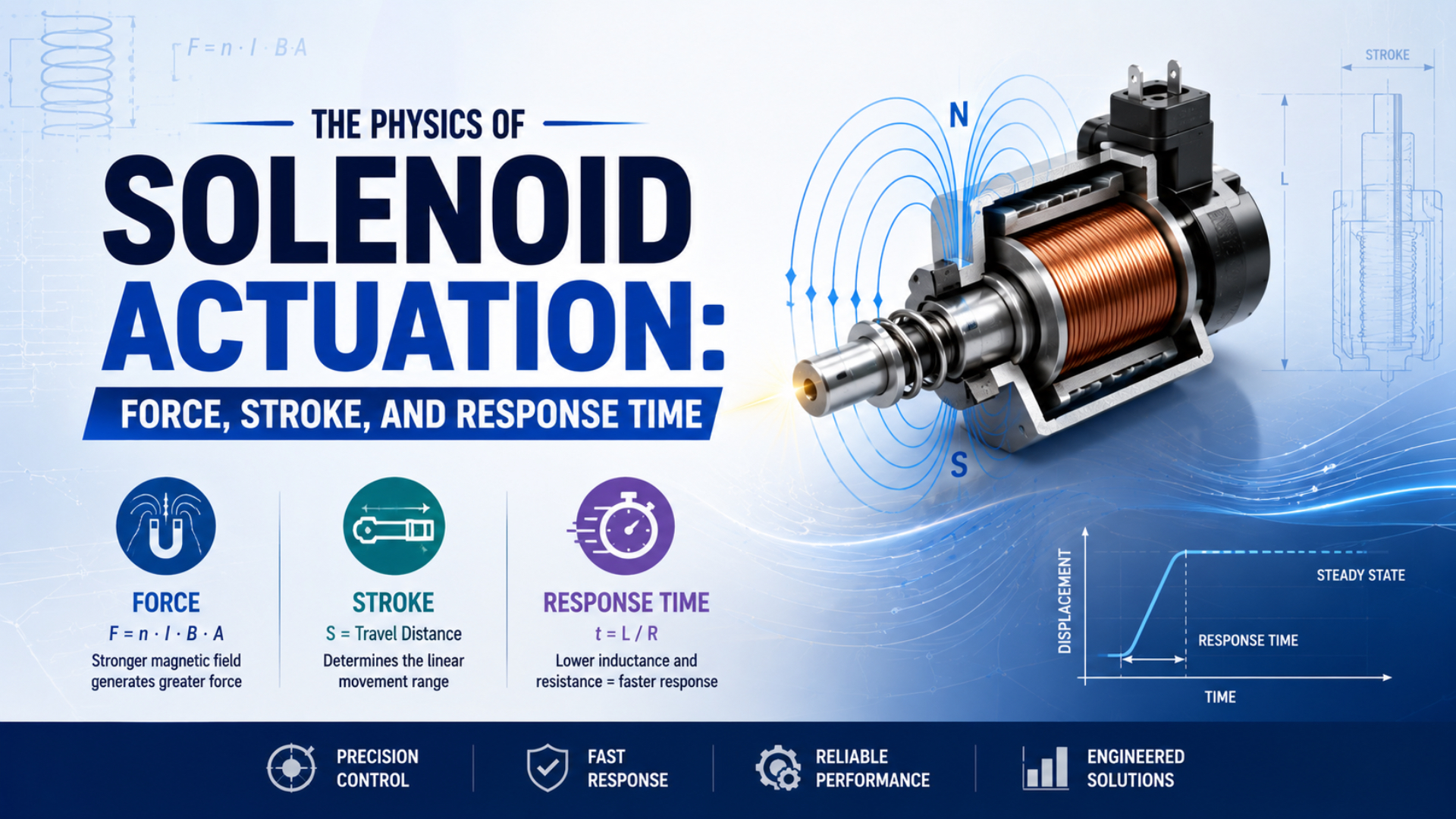
A solenoid valve does not switch simply because voltage reaches the coil. Current must build, magnetic force must exceed the opposing load at the present armature position, and the moving assembly must complete its stroke. Only then can the valve change the pneumatic path. Force, stroke, and response time are therefore one coupled design problem.
Key Takeaways
- ISO 12238:2023 covers shifting-time tests for 2- and 3-position directional valves.
- Magnetic force must exceed the complete load at every required stroke position.
- A simple inverse-square gap equation is a screening model, not a universal valve law.
- SMC’s 12 ms figure applies only to specified SY conditions.
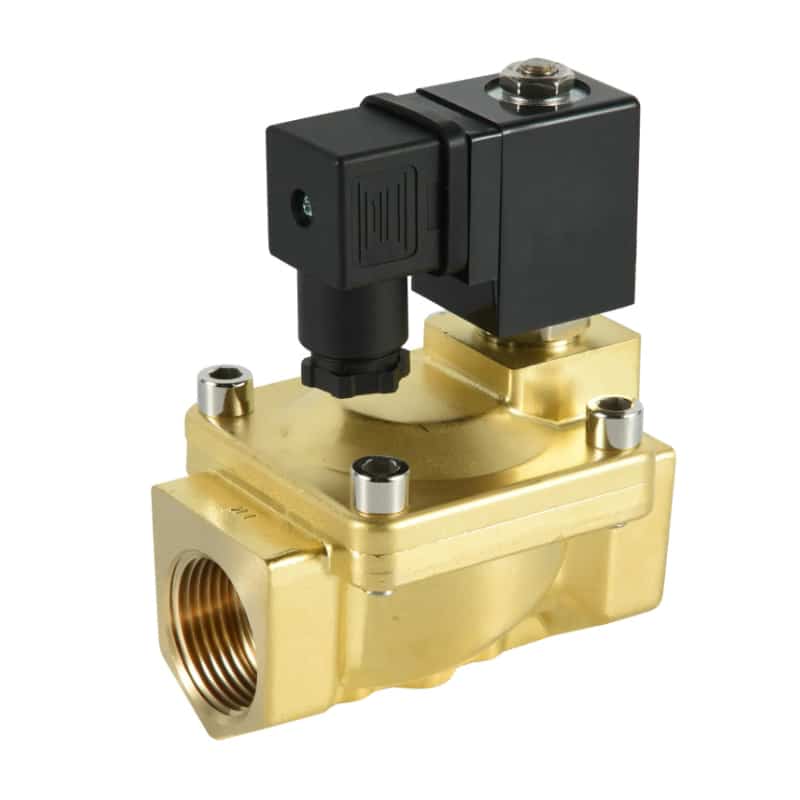
This 2/2-way valve illustrates the energy path: the coil creates a magnetic field, the armature converts that field into motion, and the internal sealing element changes the flow path. The external shape reveals little about the force margin or timing inside, so selection has to use the valve’s own curves and test conditions.
What Does Solenoid Actuation Actually Control?
ISO 12238:2023 applies to electrically or pneumatically operated directional valves with 2 or 3 positions, including monostable and bistable designs (ISO 12238, 2023). A solenoid’s immediate job is narrower: move an armature or pilot element far enough to make the valve change state.
Solenoid actuation is the conversion of an electrical command into controlled magnetic force and armature travel. It ends at a defined mechanical or valve event, not automatically at the actuator’s final pneumatic result.
That distinction prevents a common timing error. The coil produces magnetic flux. The flux creates force on the armature. Armature movement then opens a seat, moves a spool, or vents a pilot chamber. In a pilot-operated valve, main-stage movement can continue after the solenoid has completed its own short stroke.
The actuation chain is best separated into five physical events:
- The electrical driver applies voltage or regulated current.
- Coil current and magnetic flux rise.
- Magnetic force exceeds the starting load.
- The armature completes its mechanical stroke.
- The valve element changes pressure or flow at the selected measurement point.
The direct-acting versus pilot-operated valve guide explains why the fifth event differs between valve architectures. A direct-acting plunger may move the main seal. A pilot solenoid may move only a small pilot seat while differential pressure moves the larger main element.
Kendrion separates two intervals. Activation delay is the time from current excitation to the start of armature movement. Stroke time is the interval from that first movement to the stroke limit. Their sum is attraction time (Kendrion technical explanations, 2018):
Here, each time is measured in seconds or milliseconds using the same event definition. Pneumatic pressure rise is a later event and should not be folded into attraction time unless the specification explicitly defines it that way.
Force, Stroke, and Load Form One Operating Margin
Kendrion documents 3 distinct families of magnetic force-stroke curves: dropping, horizontal, and climbing toward the stroke limit (Kendrion, retrieved 2026-07-22). The curve is not a cosmetic datasheet graph. It must remain above the valve’s opposing-load curve wherever motion is required.
At each armature position , define the available margin as:
is magnetic force, is coil current, and includes external opposing loads such as spring, pressure, friction, flow force, and gravity where relevant. A positive static margin starts the check. The remaining net force then drives inertia and velocity-dependent damping during motion.
Force margin is the difference between available magnetic force and the external opposing load at a specified current, position, and time. It is not a second allowance for inertia.
For a simplified axial model:
is positive when gravity opposes the commanded stroke and negative when gravity assists it. For a horizontal stroke with negligible axial weight, set it to zero. is moving mass and represents velocity-dependent damping. The equation makes the practical boundary clear: seated holding force cannot prove breakaway at the initial gap.
The weakest point can occur before the armature moves, midway through travel, or near the seat if spring compression rises sharply. Overlaying the two curves exposes that point immediately. Comparing only one nominal force with one nominal load can hide it.
Kendrion defines stroke work as the area under the magnetic force-stroke curve:
is mechanical work in joules, while and are the start and end positions in metres. Work is useful for comparing actuators, but it still does not replace a point-by-point margin check because equal areas can hide very different curve shapes.
When Is the Inverse-Square Air-Gap Model Useful?
A 2024 experimentally validated proportional-solenoid study achieved at across a 1-3 mm working range by shaping the pole geometry (Applied Sciences, 2024). That near-flat result shows why geometry can defeat a universal inverse-square force assumption.
For one dominant, uniform air gap with unsaturated magnetic material and negligible leakage, magnetic pressure gives an ideal screening estimate:
is air-gap flux density in tesla, is effective pole area in square metres, and is magnetic permeability of free space. This equation estimates local attraction from the gap field. It does not calculate the spring, pressure, friction, or flow loads inside the valve.
A further lumped approximation substitutes ampere-turns and gap length:
is coil turns, is current, is idealized pole area, and is the dominant gap. The expression explains why current and air gap matter, but only while the iron reluctance, leakage, fringing, saturation, residual gaps, and position-dependent geometry remain small enough to ignore.
The original temptation is to double and declare that force becomes one quarter. That conclusion follows from the simplified equation, not from every built solenoid. A guide tube, nonmagnetic sleeve, side gap, tapered pole, saturation region, or leakage path can change both the magnitude and shape of the curve.
For a more complete calculation, use magnetic co-energy, Maxwell stress, or a measured force-stroke map. The solenoid plunger force calculation guide covers those methods and the valve’s pressure, spring, friction, and acceleration loads in detail.
How Does Coil Current Become Pull-In Force?
Texas Instruments specifies its DRV110 for 6-48 V DC and rectified 120/230 V AC solenoid applications, with independently set peak current, keep time, and hold current (TI DRV110 datasheet, 2018). The three-stage waveform separates fast pull-in from lower-power holding instead of treating coil voltage as the whole command.
For an ideal DC coil with constant resistance and inductance , the electrical time constant is:
After a voltage step , current rises as:
is in seconds, in henries, in ohms, and in amperes. At , the ideal fixed-parameter circuit has reached about 63.2% of its final current. That is an electrical reference point, not a guaranteed armature or valve response time.
Real solenoids add two complications. First, inductance changes with armature position because magnetic reluctance changes. Second, armature motion changes flux linkage and creates a motion-related voltage term. A more general coil equation is:
is flux linkage, which depends on current and position. A 2023 high-speed-solenoid study used this coupled circuit, magnetic-field, and mechanical framework, then verified current and displacement against a laser-based test rig (Materials, 2023).
The pickup threshold is a crossing event, not a fixed multiple of . Motion begins when the rising curve first exceeds the instantaneous load. Two coils with the same nominal L/R value can cross that threshold at different times because their force-current maps, springs, friction, pressure loads, and drivers differ. Coil heating changes the comparison again. Rising winding resistance reduces steady current under voltage drive, while the hot magnetic and mechanical system may also behave differently. Use minimum voltage at the coil terminals and stabilized hot resistance for the worst pull-in check, not only the room-temperature nameplate value. This hot-coil condition can define the lower end of the verified operating envelope. The separate coil inductance and response-time article examines driver and suppression effects more closely.
Why Is Response Time More Than L/R?
A pneumatic-valve study modeled 4 coupled domains: circuit, magnetic circuit, mechanical motion, and airflow, then compared calculation with a response-characteristic test system (Measurement and Control, 2019). The result supports a practical rule: coil current rise is only one contributor to valve and machine timing.
The force-stroke interaction divides mechanical response into distinct phases:
| Phase | Armature state | Governing question |
|---|---|---|
| Current buildup | stationary at initial gap | when will magnetic force cross the starting load? |
| Breakaway | static friction is overcome | is the first positive margin large enough to start acceleration? |
| Travel | position and inductance change together | does force remain above the rising spring and pressure load? |
| Approach to seat | velocity and remaining gap fall | will the armature finish travel without rebound or stall? |
| Hold | armature is at the stroke limit | can reduced hold current preserve the required seated state? |
Response time follows the force margin through the stroke. During current buildup, the armature is stationary, so the driver, resistance, inductance, and initial air gap determine how quickly magnetic force reaches the opposing load. Breakaway occurs only after that threshold is crossed. As the armature travels, position changes inductance, flux linkage, spring load, friction, and sometimes pressure or flow force, so acceleration cannot be inferred from L/R alone. Near the seat, the remaining margin and damping determine whether travel finishes cleanly or the armature rebounds. In the hold state, a driver may reduce current only after the required position is secured. The 2019 pneumatic-valve study therefore coupled 4 domains, circuit, magnetic circuit, mechanical motion, and airflow, instead of treating coil timing as the complete response (Measurement and Control, 2019).
Energizing and de-energizing still require separate measurements. On release, the driver clamp controls current decay; residual magnetic force, spring return, friction, pilot pressure, and exhaust conditions govern what follows. There is no defensible rule that every valve must open faster than it closes, or the reverse.
The AC versus DC solenoid coil comparison explains why supply type alone cannot rank complete response. For the downstream timing budget and fill calculation, use the separate valve shift-time analysis.
What Does a Millisecond Rating Actually Mean?
SMC lists 12 ms or less for one SY3000 2-position single-solenoid condition at 0.5 MPa, rated voltage, and 20°C coil temperature; other SY sizes and suppressor options have different limits (SMC SY3000/5000/7000 catalog, retrieved 2026-07-22). The conditions are part of the number.
ISO 12238:2023 exists because shifting time needs a defined procedure. It specifies test methods for electrically and pneumatically operated directional valves, rather than endorsing one universal response range. A catalog value can be useful for comparing configurations only when function, pressure, voltage, temperature, suppressor, test point, and stated method align.
Before using any millisecond figure, record these fields:
| Required field | Why it changes the interpretation |
|---|---|
| Valve model and function | a 2-position single, double, or 3-position valve may have different timing |
| Operating pressure | changes pilot and pressure forces |
| Coil voltage at switching | controls current rise and force margin |
| Coil temperature | changes winding resistance |
| Surge suppressor or driver | changes pickup or release current waveform |
| Timing direction | energize, de-energize, open, close, and return are different events |
| Measurement endpoint | armature movement, valve shift, outlet pressure, or machine sensor |
| Downstream volume and plumbing | changes pneumatic fill and exhaust delay |
A response number without an endpoint cannot be added to a cycle-time budget. “Command to armature movement” and “command to 90% pressure at the cylinder port” may both be valid measurements, but they answer different questions. The solenoid valve response-time measurement guide shows how to synchronize electrical and pressure traces.
A Practical Selection and Verification Workflow
Kendrion divides attraction into 2 measured intervals, activation delay and stroke time, while ISO 12238:2023 standardizes directional-valve shifting-time tests (Kendrion, 2018; ISO, 2023). A sound workflow preserves both boundaries instead of trying to solve every delay with one coil specification.
- Define the switched element. Identify whether the solenoid moves a main poppet, a spool, or only a pilot seat. Record normally open or closed behavior and monostable or bistable function.
- State the required stroke. Use the actual armature or pilot travel, including assembly tolerances. Do not substitute valve port size or spool travel unless they are the same physical motion.
- Build the load curve. Include spring preload and rate, differential-pressure force, seal or guide friction, flow force, orientation, and the moving mass.
- Obtain force-stroke data. Use curves at the relevant current, coil temperature, and duty cycle. A holding-force headline is not enough.
- Check the minimum margin. Compare available and required force from initial gap to seat. Confirm that the peak-current duration is long enough to complete motion.
- Define the response endpoint. Write “command to first armature motion,” “command to valve shift,” or “command to stated outlet-pressure threshold.”
- Test the corners. Measure low coil-terminal voltage, hot resistance, minimum and maximum pressure, intended suppressor, realistic plumbing, and both switching directions.
- Separate valve and machine delays. If outlet pressure changes promptly but cylinder motion is late, investigate flow, tube volume, exhaust, load, and cushioning before replacing the coil.
For troubleshooting, capture coil voltage and current on the same time base as outlet pressure. Current that rises normally without motion points toward inadequate force margin, sticking, excessive pressure load, or a mechanical fault. Late current rise points first toward the supply, driver, wiring, resistance, or inductance. The pneumatic solenoid valve troubleshooting guide provides the wider fault sequence.
The final engineering record should contain the force-stroke curve, load assumptions, current waveform, coil temperature, pressure, suppressor, timing direction, and measurement endpoint. That packet is much more transferable than a statement that the valve is “fast.”
Solenoid Actuation FAQs: Force, Stroke, and Response Time
ISO 12238:2023 covers 2- and 3-position directional valves, but it does not make one millisecond value universal (ISO 12238, 2023). These answers keep force, armature stroke, valve shift, and downstream pneumatic response separate so engineers can compare datasheets and measurements on the same basis.
Does doubling the air gap always reduce solenoid force to one quarter?
No. That result belongs to an ideal single-gap model with fixed current, uniform area, negligible leakage, unsaturated iron, and no other important reluctance. Real guide tubes, tapered poles, residual gaps, fringing, saturation, and position-dependent inductance change the curve. Use the simple equation for screening, then check model-specific or measured force-stroke data.
Is a solenoid’s holding force the correct value for valve selection?
Not by itself. Holding force is measured near the stroke limit, where the working gap is commonly smallest. Pull-in begins at the initial position and must overcome spring preload, pressure load, static friction, and inertia. Select against the minimum positive force margin across the full commanded stroke, not the largest seated-force value.
Does one L/R time constant equal valve response time?
No. One ideal fixed-parameter L/R time constant reaches about 63.2% of final current, but movement begins at a force threshold. Position-dependent inductance, hot resistance, driver behavior, spring and pressure loads, armature travel, valve architecture, and downstream air volume all add or alter delay. Define and measure the required endpoint directly.
Can higher voltage always make a solenoid valve faster?
Only within an approved drive strategy and component ratings. More applied voltage can increase the current-rise rate, but it also changes heating, insulation stress, driver stress, and peak current. Use the coil and driver limits, peak-current duration, hot resistance, and required hold current. Never use uncontrolled overvoltage as a field-speed adjustment.
Why can two datasheets list different response times for similar valves?
They may use different valve functions, pressures, coil temperatures, suppressors, voltages, timing directions, downstream volumes, or endpoints. SMC’s SY figures, for example, are tied to 0.5 MPa, rated voltage, 20°C coil temperature, and specific configurations. Compare the test conditions first; then compare the millisecond values.
Sources and technical references
- ISO 12238:2023: Pneumatic fluid power, directional control valves, measurement of shifting time, published 2023-02, retrieved 2026-07-22.
- Texas Instruments DRV110 Solenoid Current Controller Datasheet, Rev. G, revised 2018-03, retrieved 2026-07-22.
- SMC SY3000/5000/7000/9000 Series Catalog, retrieved 2026-07-22.
- Kendrion, Electromagnets and Actuators: Technical Explanations, 2018, retrieved 2026-07-22.
- Zhang et al., Numerical Calculation and Experimental Study on Response Characteristics of Pneumatic Solenoid Valves, 2019, retrieved 2026-07-22.
- Keles et al., The Design and Analysis of a Proportional Solenoid with Experimental Validation, 2024, retrieved 2026-07-22.
- Eddy Effect and Dynamic Response of High-Speed Solenoid Valve with Composite Iron Core, 2023, retrieved 2026-07-22.